Table of Contents
Advertisement
Quick Links
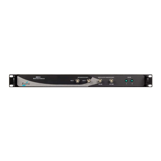
RRS11
Solid-State Transfer Switch
Installation and Operation Manual
Part Number MN-RRS11
Rev. 3
August 17, 2010
IMPORTANT NOTE: The information contained in this document supersedes all previously
published information regarding this product. This manual is subject to change without prior notice.
Part Number MN-RRS11
Revision 3
Advertisement
Table of Contents

Related Manuals for Comtech EF Data RADYNE RRS11


Summary of Contents for Comtech EF Data RADYNE RRS11
- Page 1 RRS11 Solid-State Transfer Switch Installation and Operation Manual Part Number MN-RRS11 Rev. 3 August 17, 2010 IMPORTANT NOTE: The information contained in this document supersedes all previously published information regarding this product. This manual is subject to change without prior notice. Part Number MN-RRS11 Revision 3...
- Page 2 Copyright © 2010 Comtech EF Data. All rights reserved. Printed in the USA. Comtech EF Data, 2114 West 7th Street, Tempe, Arizona 85281 USA, 480.333.2200, FAX: 480.333.2161...
-
Page 3: Table Of Contents
Table of Contents TABLE OF CONTENTS ......................III CHAPTER 1. INTRODUCTION .................. 1–1 Overview ............................1–1 CHAPTER 2. INSTALLATION ................... 2–1 Installation Requirements ......................2–1 Unpacking ............................ 2–2 2.2.1 Test Data Sheet ........................2–2 System Connections ........................2–2 CHAPTER 3. OPERATION ..................3–1 Solid-State Transfer Switch Operation .................. - Page 4 Table of Contents MN-RRS11 RRS11 Solid-State Transfer Switch Rev. 3 Notes:...
-
Page 5: About This Manual
PREFACE About this Manual This manual describes the installation and operation for the Radyne RRS11. This is a technical document intended for earth station engineers, technicians, and operators responsible for the operation and maintenance of the RRS11. Reporting Comments or Suggestions Concerning this Manual Comments and suggestions regarding the content and design of this manual are appreciated. -
Page 6: Cautions And Warnings
RRS11 Solid-State Transfer Switch MN-RRS11 Preface Rev. 3 Cautions and Warnings IMPORTANT or NOTE indicates a statement associated with the task being performed or information critical for proper equipment function. IMPORTANT CAUTION indicates a hazardous situation that, if not avoided, may result in minor or moderate injury. -
Page 7: Safety Compliance
RRS11 Solid-State Transfer Switch MN-RRS11 Preface Rev. 3 Safety Compliance EN 60950 Applicable testing is routinely performed as a condition of manufacturing on all units to ensure compliance with safety requirements of EN60950.This equipment meets the Safety of Information Technology Equipment specification as defined in EN60950. Low Voltage Directive (LVD) The following information is applicable for the European Low Voltage Directive (EN60950): <HAR>... - Page 8 The warranty does not apply to any part of a product that has been installed, altered, repaired, or misused in any way that, in the opinion of Comtech EF Data Corporation, would affect the reliability or detracts from the performance of any part of the product, or is damaged as the result of use in a way or with equipment that had not been previously approved by Comtech EF Data Corporation.
- Page 9 The remedies provided herein are the buyer’s sole and exclusive remedies. Comtech EF Data shall not be liable for any direct, indirect, special, incidental, or consequential damages, whether based on contract, tort, or any other legal...
-
Page 10: Customer Support
480.333.2200 (Main Comtech EF Data number) 480.333.4357 (Customer Support Desk) 480.333.2161 FAX To return a Comtech EF Data product (in-warranty and out-of-warranty) for repair or replacement: • Contact the Comtech EF Data Customer Support Department. Be prepared to supply the Customer Support representative with the model number, serial number, and a description of the problem. -
Page 11: Chapter 1. Introduction
Chapter 1. INTRODUCTION Overview The RRS11 Solid State Transfer Switch offers IF or L-Band redundancy for the DM240XR in a simple straight forward plug and play design. The RRS11 includes monitor ports that allows the user access to the online and offline ports. The RRS11 also includes front panel LEDs that indicate online status of the modulator. - Page 12 RRS11 Solid-State Transfer Switch Introduction Notes: MN-RRS11 1–2 Rev. 3...
-
Page 13: Chapter 2. Installation
Chapter 2. Installation This section provides unpacking and installation instructions, and a description of external connections, status and contact closure alarm information. Installation Requirements The RRS11 Solid-State Transfer Switches is a standard one rack unit (1RU) high (1.75 inches/4.45 cm) vertically, 19 inches (48.3 cm) wide, and 17 inches (43.2 cm) deep. The RRS11 Switch is installed between two DM240-PIIC or DM240XR modulators. -
Page 14: Unpacking
RRS11 Solid-State Transfer Switch Installation Unpacking The RRS11 Solid-State Transfer Switch was carefully packaged to avoid damage and should arrive complete with the following items for proper installation: RRS11 Solid-State Transfer Switch Unit RRS11 Test Data Sheet Interconnect Cables (IF, Monitor and Control) ... -
Page 15: System Connections
RRS11 Solid-State Transfer Switch Installation System Connections Figures 2-1 illustrates a typical setup with an RRS11-L and two DM240-PIIC modulators. Figure 2-2 illustrates a typical setup with RRS11 and two DM240XR modulators. For initial Solid-State Transfer Switch setup and configuration, perform the following procedure: 1. - Page 16 RRS11 Solid-State Transfer Switch Installation Figure 2-2 Cable Connections between RRS11 and two DM240XR Units Table 2-2 70/140 MHz Interconnect Cable Part Numbers Cable Quantity Description Part Number Control Cable (DB-9 Straight Cable) CA/3677-1 IF - BNC/BNC 75 Ohm Cable CA/3598-12 L-Band Cable (50 Ohm SMA) CA/5127AMAM-16...
-
Page 17: Chapter 3. Operation
Chapter 3. Operation Solid-State Transfer Switch Operation A functional block diagram of the RRS11/RRS11-L signal flow is illustrated in Figure 3-1 below. MN-RRS11 3–1 Rev. 3... - Page 18 RRS11 Solid-State Transfer Switch Operation Figure 3-1 RRS11 Functional Block Diagram MN-RRS11 3–2 Rev. 3...
-
Page 19: Operating Procedures
RRS11 Solid-State Transfer Switch Operation Operating Procedures The Solid-State Transfer Switch is designed for minimal operator intervention and control during normal operation. After initial setup, the unit should operate in a relatively ‘transparent’ manner, providing trouble-free backup of the online modulators Solid-State Transfer Switch Backup Operation The RRS11 Switch monitors the fault status from each modulator. - Page 20 RRS11 Solid-State Transfer Switch Operation Table 3-1A, RRS11-L L-Band Rear Panel Connectors Connector Nomenclature Description Online Status 9-Pin D-Sub Switch Status Form-C Relay Outputs Output Prime Mod Control 9-Pin D-Sub Control Connector From Prime Modulator Backup Mod Control 9-Pin D-Sub Control Connector From Backup Modulator Monitor A Input SMA 50 Ohm from Modulator A Monitor Output Monitor B Input...
- Page 21 RRS11 Solid-State Transfer Switch Operation An additional 9-Pin D-Sub Connector is supplied for switch monitoring. The I/O on this connector comes from a Form-C relay. The pinouts for the monitor connector is listed in Table 3-3. Table 3-3. Switch Online Statue Pinout Pin No.
- Page 22 RRS11 Solid-State Transfer Switch Operation Notes: MN-RRS11 3–6 Rev. 3...
-
Page 23: Chapter 4. Maintenance And Troubleshooting
Chapter 4. Maintenance and Troubleshooting Basic Troubleshooting and Maintenance This section provides information on the basic troubleshooting and repair procedures for the Solid-State Transfer Switch that may be performed on-site by qualified personnel. Only minor repairs will be discussed. For serious failures, the user should not attempt to repair the unit without first contacting Radyne Corporation Customer Service Department at 602-437-9620 for further information and instructions. - Page 24 RRS11 Solid-State Transfer Switch Maintenance and Troubleshooting Notes: MN-RRS11 4–2 Rev. 3...
-
Page 25: Chapter 5. Technical Specifications
Chapter 5. Technical Specifications RRS11 and RRS11 L Technical Specifications Introduction - RRS11 L-Band Switch This section defines the technical performance parameters and specifications for the Solid-State Transfer Switch. The RRS11L is intended to operate with the DM240-PIIC or DM240XR modulators. -
Page 26: Power And Environmental
RRS11 Solid-State Transfer Switch Technical Specifications 5.2.2 Power and Environmental Prime Power: +12 VDC provided to the Unit through the Prime and Backup Cabling from the Modulators Operating Temp: 0 to 50°C, 95% Humidity, Non-Condensing Storage Temp: -20 to 70°C, 99% Humidity, Non-Condensing 5.2.3 Physical Size: 19”... - Page 27 METRIC CONVERSIONS Units of Length Unit Centimeter Inch Foot Yard Mile Meter Kilometer Millimeter 1 centimeter — 0.3937 0.03281 0.01094 0.01 — — 6.214 x 10 1 inch 2.540 — 0.08333 0.2778 1.578 x 10 0.254 — 25.4 1 foot 30.480 12.0 —...
- Page 28 2114 85281 WEST TH STREET TEMPE ARIZONA 480 • 333 • 2200 PHONE 480 • 333 • 2161...