Table of Contents
Advertisement
Quick Links
CRS-311
1:1 Redundancy Switch
Installation and Operation Manual
Accessory Product for use only with Comtech EF Data
CDM-Qx/QxL and SLM-5650/5650A Modems
(Modem Firmware and Hardware Requirements Apply)
IMPORTANT NOTE:
The information contained in this document supersedes all previously published
information regarding this product. Product specifications are subject to change without prior notice.
Part Number MN/CRS311.IOM Revision 7
Advertisement
Table of Contents

Related Manuals for Comtech EF Data CRS-311


Summary of Contents for Comtech EF Data CRS-311
- Page 1 CRS-311 1:1 Redundancy Switch Installation and Operation Manual Accessory Product for use only with Comtech EF Data CDM-Qx/QxL and SLM-5650/5650A Modems (Modem Firmware and Hardware Requirements Apply) IMPORTANT NOTE: The information contained in this document supersedes all previously published information regarding this product. Product specifications are subject to change without prior notice.
- Page 2 Copyright © Comtech EF Data, 2012. All rights reserved. Printed in the USA. Comtech EF Data, 2114 West 7th Street, Tempe, Arizona 85281 USA, 480.333.2200, FAX: 480.333.2161...
-
Page 3: Table Of Contents
TABLE OF CONTENTS TABLE OF CONTENTS ......................III TABLES ............................IX FIGURES ............................ IX PREFACE ..........................XIII About this Manual .......................... xiii Reporting Comments or Suggestions Concerning this Manual ............. xiii Related Documents .......................... xiii Conventions and References ...................... xiii Patents and Trademarks ........................ xiii Warnings, Cautions, and Notes ...................... xiv Examples of Multi‐Hazard Notices ...................... xiv Recommended Standard Designations .................... xiv Metric Conversion .......................... xiv Safety and Compliance ........................ xv Electrical Safety and Compliance...................... xv Electrical Installation .......................... xv Operating Environment .......................... xv European Union Radio Equipment and Telecommunications Terminal Equipment (R&TTE) Directive (1999/5/EC) and EN 301 489‐1 ..................... xv European Union Electromagnetic Compatibility (EMC) Directive (2004/108/EC) ... -
Page 4: Table Of Contents
CRS-311 1:1 Redundancy Switch Revision 7 Table of Contents MN/CRS311.IOM 1.2 CRS‐311 Switch/Modem Compatibility ................ 1–5 1.3 CRS‐311 Physical Features .................... 1–6 1.3.1 Dimensional Envelopes ...................... 1 –6 1.3.2 Front Panel .......................... 1 –7 1.3.3 Rear Panel .......................... 1 –7 1.3.3.1 CRS‐311 System Controller and Power Supply Modules .......... 1 –8 1.3.3.2 CRS‐351 Overhead Switch Module ................. 1 –8 1.3.3.3 CRS‐281x IF Switch Modules ................... 1 –9 ... - Page 5 CRS-311 1:1 Redundancy Switch Revision 7 Table of Contents MN/CRS311.IOM 3.3.3.1 EIA‐530 Data Traffic Connections ................. 3 –18 3.3.3.2 Balanced G.703 Data Traffic Connections .............. 3 –18 3.3.3.3 Unbalanced G.703 Data Traffic Connections .............. 3 –19 3.3.3.4 HSSI Data Traffic Connections.................. 3 –19 3.3.4 Serial User Data Connections – CRS‐311 to User .............. 3 –19 3.3.5 Ethernet M&C Connections – CRS‐311 to User .............. 3 –23 3.3.5.1 Single‐Port Ethernet Bridge Mode M&C Using the GbE Interface Module .... 3 –23 ...
- Page 6 CRS-311 1:1 Redundancy Switch Revision 7 Table of Contents MN/CRS311.IOM 4.5.2.2 Downloading and Extracting the Firmware Update ............. 4 –14 4.6 CRS‐311 Front Panel Configuration .................. 4–17 4.6.1.1 Set Operation Mode ..................... 4 –17 4.6.1.2 Set Holdoff Period ...................... 4 –18 4.6.1.2.1 Set Backup Holdoff Period .................. 4 –18 4.6.1.2.2 Set Restore Holdoff Period .................. 4 –19 4.6.1.3 Set Alarm Masking ...................... 4 –19 CHAPTER 5. ...
- Page 7 CRS-311 1:1 Redundancy Switch Revision 7 Table of Contents MN/CRS311.IOM 5.2.5.5 (MONITOR:) IO ...................... 5 –16 5.2.6 STORE/LD (Store or Load Configuration) ................ 5 –17 5.2.6.1 (STORE/LD) STORE ...................... 5 –17 5.2.6.2 (STORE/LD) LOAD ...................... 5 –18 5.2.7 UTILITY ........................... 5 –18 5.2.7.1 (UTILITY:) SET‐RTC (Set Real‐Time Clock) .............. 5 –18 ...
- Page 8 CRS-311 1:1 Redundancy Switch Revision 7 Table of Contents MN/CRS311.IOM A.4 Data Traffic / IF Cables ...................... A ‐14 A.4.1 EIA‐232/422, EIA‐530 Control and Data Cable (DB‐25M to DB‐25F) ........ A‐15 A.4.2 Balanced G.703 Data Cable (DB‐15M to DB‐15F) .............. A‐16 A.4.3 Balanced G.703 / IF Cable, BNC (75Ω) ................... A‐17 A.4.4 HSSI Data Cable (HD‐50M to HD‐50M) .................. A‐18 A.4.5 Quad E1 Data Cable for CDM‐Qx/QxL (DB‐15F to 4X RJ‐45) .......... A‐19 A.4.6 Quad E1 / Gigabit Ethernet Connector Cable (RJ‐45 to RJ‐45) .......... A‐20 A.4.7 IF Cable, BNC (50Ω)........................ A‐21 A.4.8 IF Cable, Type ‘N’ (50Ω) ...................... A‐22 ...
- Page 9 CRS-311 1:1 Redundancy Switch Revision 7 Table of Contents MN/CRS311.IOM APPENDIX E. CRS-311 RETROFIT FOR SLM-5650/5650A NP INTERFACE OPERATION ..E–1 E.1 Introduction ........................ E–1 E.1.1 Field Upgrade Kit KT‐0000078 (Required for Retrofit) ............ E–1 E.1.2 Retrofit Procedure ........................ E–2 TABLES Table 1‐1. CRS‐311 Switch/Modem Compatibility .................. 1–5 Table 4‐1. CRS‐505 RMI Factory‐configured Jumper Settings .............. 4–8 Table 4‐2. CRS‐515 TMI Factory‐configured Jumper Settings.............. 4–10 Table B‐1. “485 Pass‐Through” User Data Connector ................ B –2 Table B‐2. “Remote Control” User Data Connector .................. B –2 ...
- Page 10 CRS-311 1:1 Redundancy Switch Revision 7 Table of Contents MN/CRS311.IOM Figure 1‐19. CRS‐316 TMI RS422 or GbE (PL/12498‐1) .................. 1–14 Figure 1‐20. CRS‐325 TMI G.703 (PL/11492‐1) .................... 1–14 Figure 1‐21. CRS‐336 TMI HSSI or GbE (PL/12499‐1) .................. 1–14 Figure 1‐22. CRS‐365 TMI .......................... 1–14 Figure 1‐23. CRS‐515 TMI 4‐Port Ethernet (PL‐0000294) ................ 1–14 Figure 2‐1. Unpacking and Inspecting the Shipment .................. 2–1 Figure 2‐2. Installing into a Rack Enclosure ...................... 2–3 Figure 2‐3. Installing the Optional Rear‐Mounting Support Brackets Kit ............ 2–4 Figure 2‐4. Installing the Modem Optional Bearingless Rack Slide Set ............ 2–6 Figure 3‐1. CDM‐Qx/QxL Cabling Example – RS‐485 Multi‐drop Cable ............. 3–7 Figure 3‐2. CDM‐Qx/QxL Control ‘Y’ and EIA‐530/RS‐232 Data Traffic Cables .......... 3–8 Figure 3‐3. CDM‐Qx/QxL Control ‘Y’ and Balanced G.703 Data Traffic Cables .......... 3–9 Figure 3‐4. CDM‐Qx/QxL Control ‘Y’ and Unbalanced G.703 Data Traffic Cables ........... 3–10 Figure 3‐5. CDM‐Qx/QxL Control and HSSI Data Traffic Cables ............... 3–11 Figure 3‐6. CDM‐Qx/QxL Control and Quad E1 Data Traffic Cables .............. 3–12 Figure 3‐7. CDM‐Qx IF Cabling Example – CRS‐281 (70/140 MHz, 50Ω or 75Ω BNC) ........ 3–14 Figure 3‐8. CDM‐QxL IF Cabling Example – CRS‐281A (L‐Band) ............... 3–15 Figure 3‐9. SLM‐5650/5650A Control and EIA‐530 Data Traffic Cables ............ 3–20 ...
- Page 11 CRS-311 1:1 Redundancy Switch Revision 7 Table of Contents MN/CRS311.IOM Figure 4‐3. CEFD P/N PL‐0000293 CRS‐505 RMI PCB .................. 4–8 Figure 4‐4. CEFD P/N PL‐0000294 CRS‐515 TMI PCB .................. 4–9 Figure 5‐1. CRS‐311 Front Panel ......................... 5–1 Figure 5‐2. CRS‐311 Menu Tree .......................... 5–5 Figure A‐1. DCE Conversion Cable: EIA‐530 to EIA‐422/449 ................ A ‐2 Figure A‐2. DCE Conversion Cable: EIA‐530 to V.35 .................... A ‐3 Figure A‐3. Switch M&C / Firmware Update Cable ..................... A ‐4 Figure A‐4. Optional EIA‐485 Multi‐Drop Ribbon Cable (CEFD P/N CA‐0000095) .......... A ‐6 Figure A‐5. Standard EIA‐485 Multi‐Drop Shielded Cable (CEFD P/N CA‐0000096) .......... A ‐7 Figure A‐6. EIA‐485 Cable Termination (CEFD P/N CA/WR11418‐1) .............. A ‐8 ...
- Page 12 CRS-311 1:1 Redundancy Switch Revision 7 Table of Contents MN/CRS311.IOM This page is intentionally blank ...
-
Page 13: Preface
PREFACE About this Manual This manual provides installation and operation information for the Comtech EF Data CRS‐311 1:1 Redundancy Switch. This is an informational document intended for the persons responsible for the operation and maintenance of the CRS‐311. Reporting Comments or Suggestions Concerning this Manual Comments and suggestions regarding the content and design of this manual are appreciated. To submit comments, please contact the Comtech EF Data Technical Publications Department: TechnicalPublications@comtechefdata.com Related Documents This manual assumes user familiarity with the Comtech EF Data products listed here. The information presented in this manual does not serve as replacement documentation for these products. ... -
Page 14: Warnings, Cautions, And Notes
CRS-311 1:1 Redundancy Switch Revision 7 Preface MN/CRS311.IOM Warnings, Cautions, and Notes A WARNING gives information about a possible hazard that MAY CAUSE DEATH or SERIOUS INJURY. A CAUTION gives information about a possible hazard that MAY CAUSE INJURY or PROPERTY DAMAGE. -
Page 15: Safety And Compliance
CRS-311 1:1 Redundancy Switch Revision 7 Preface MN/CRS311.IOM The user should carefully review the following information: Safety and Compliance Electrical Safety and Compliance The unit complies with the EN 60950 Safety of Information Technology Equipment (Including Electrical Business Machines) safety standard. IF THE UNIT IS OPERATED IN A VEHICLE OR MOVABLE INSTALLATION, MAKE SURE THE UNIT IS STABLE. OTHERWISE, EN 60950 SAFETY IS NOT GUARANTEED. Electrical Installation CONNECT THE UNIT TO A POWER SYSTEM THAT HAS SEPARATE GROUND, LINE AND NEUTRAL CONDUCTORS. DO NOT CONNECT THE UNIT WITHOUT A DIRECT CONNECTION TO GROUND. • Sect 3.2.2 CTOG‐250 Power and Ground Connections •... -
Page 16: European Union Electromagnetic Compatibility (Emc) Directive (2004/108/Ec)
CRS-311 1:1 Redundancy Switch Revision 7 Preface MN/CRS311.IOM Common technical requirements), and the Declarations of Conformity for the applicable directives, standards, and practices that follow: European Union Electromagnetic Compatibility (EMC) Directive (2004/108/EC) • Emissions: EN 55022 Class A – Limits and Methods of Measurement of Radio ... -
Page 17: European Union Low Voltage Directive (Lvd) (2006/95/Ec)
CRS-311 1:1 Redundancy Switch Revision 7 Preface MN/CRS311.IOM European Union Low Voltage Directive (LVD) (2006/95/EC) Symbol Description <HAR> Type of power cord required for use in the European Community. CAUTION: Double‐pole/Neutral Fusing ACHTUNG: Zweipolige bzw. Neutralleiter‐Sicherung International Symbols Symbol Definition Symbol Definition Alternating Current Protective Earth Fuse Chassis Ground For additional symbols, refer to Warnings, Cautions and Notes listed earlier in this ... -
Page 18: Warranty Policy
CRS-311 1:1 Redundancy Switch Revision 7 Preface MN/CRS311.IOM Warranty Policy Comtech EF Data products are warranted against defects in material and workmanship for a specific period from the date of shipment, and this period varies by product. In most cases, the warranty period is two years. During the warranty period, Comtech EF Data will, at its option, repair or replace products that prove to be defective. Repairs are warranted for the remainder of the original warranty or a 90 day extended warranty, ... -
Page 19: Exclusive Remedies
CRS-311 1:1 Redundancy Switch Revision 7 Preface MN/CRS311.IOM The warranty excludes any responsibility by Comtech EF Data Corporation for incidental or consequential damages arising from the use of the equipment or products, or for any inability to use them either separate from or in combination with any other equipment or products. A fixed charge established for each product will be imposed for all equipment returned for warranty repair where Comtech EF Data Corporation cannot identify the cause of the reported failure. Exclusive Remedies Comtech EF Data Corporation’s warranty, as stated is in lieu of all other warranties, ... -
Page 20: Getting Help
CRS-311 1:1 Redundancy Switch Revision 7 Preface MN/CRS311.IOM Getting Help Review the Warranty Policy before contacting Comtech EF Data Technical Support or Customer Service. Contacting Comtech EF Data Contact Comtech EF Data for: • Technical Support – Product support or training. • Customer Service – Information on returning an in‐warranty or out‐of‐warranty product for upgrade or repair. Be prepared to provide the product model number and its serial ... -
Page 21: Returning A Product For Upgrade Or Repair
CRS-311 1:1 Redundancy Switch Revision 7 Preface MN/CRS311.IOM Returning a Product for Upgrade or Repair Step Task Go to the Comtech EF Data Home page (http://www.comtechefdata.com). From 1 the SUPPORT column at the bottom of the page, select the Service hyperlink, and read the Return Material Authorization section in its entirety. 2 Request a Return Material Authorization Number: • On the Comtech EF Data Home page: From the SUPPORT column at the bottom of the page, select the RMA Request hyperlink; OR • On the Comtech EF Data Support page: Click [Send RMA Request]; ... - Page 22 CRS-311 1:1 Redundancy Switch Revision 7 Preface MN/CRS311.IOM Notes: xxii...
-
Page 23: Chapter 1. Introduction
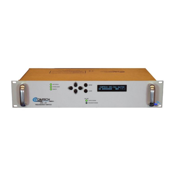
Figure 1-1. CRS-311 1:1 Redundancy Switch The Comtech EF Data CRS‐311 1:1 Redundancy Switch (Figure 1‐1) – also referred to throughout this manual as “the Switch” – is a companion product for use with the Comtech EF Data CDM‐Qx/QxL or SLM‐5650/5650A Satellite Modems. The CRS‐311 is designed to continuously monitor a pair of modems in a 1:1 redundant ... -
Page 24: Figure 1-2. Crs-311 System-Level Block Diagram
Figure 1-2. CRS-311 System-Level Block Diagram Construction Features: The CRS‐311 is modular in construction. All replaceable modules are installed into slots provided at the rear panel – this includes the CRS‐230 System Controller; Traffic Modem Interface (TMI); Redundant Modem Interface (RMI); Overhead Module; IF ... - Page 25 CRS-311 1:1 Redundancy Switch Revision 7 Introduction MN/CRS311.IOM • The TMI can be completely removed from the CRS‐311, with cables still attached, and traffic is not interrupted or affected. Ease of Connection: Connection to the Traffic and Redundant Modems is simple. One cable connected to the HD‐15 port on the TMI or RMI carries the Switch‐to‐Modem communications, fault indications, and remote control. • For the CDM‐Qx/QxL: These modems require an additional EIA‐485 multi‐drop cable ...
- Page 26 CRS-311 1:1 Redundancy Switch Revision 7 Introduction MN/CRS311.IOM • CRS‐281 (70/140 MHz IF) with Type ‘BNC’ (75Ω) connectors • CRS‐281L (L‐Band IF) with Type ‘N’ (50Ω) connectors Two CRS‐281x switch modules are compatible for use with the SLM‐5650/5650A modem: • CRS‐281 (70/140 MHz IF) with Type ‘TNC’ (50Ω) connectors. • CRS‐281L (L‐Band IF) with Type ‘N’ (50Ω) connectors. The SLM‐5650/5650A modem permits simultaneous operation of the Tx IF and Rx IF bands at 70/140 MHz and L‐Band frequencies, independent of one another. If you want the Tx and Rx to be of different IF bands, the CRS‐281x module must be ...
-
Page 27: Switch/Modem Compatibility
CRS-311 1:1 Redundancy Switch Revision 7 Introduction MN/CRS311.IOM CRS-311 Switch/Modem Compatibility Table 1‐1 shows the Comtech EF Data modems that are compatible for use with the CRS‐311 1:1 Redundancy Switch: Table 1-1. CRS-311 Switch/Modem Compatibility Modem Optional Switch Modules CRS-281 IF Switch Module (70/140 MHz) - 50Ω or 75Ω BNC CDM-Qx Up to one modulator and one demodulator allowed per CDM‐Qx/QxL. CRS-281A IF Switch Module (L-Band) CDM-QxL Up to one modulator and one demodulator allowed per ... -
Page 28: Physical Features
CRS-311 1:1 Redundancy Switch Revision 7 Introduction MN/CRS311.IOM CRS-311 Physical Features 1.3.1 Dimensional Envelopes Figure 1‐3 shows the dimensional envelope for the CRS‐311 1:1 Redundancy Switch. Figure 1-3. CRS-311 Dimensional Envelope 1–6... -
Page 29: Front Panel
Feature Description Feature Description CRS-241 AC Power Supply CRS-281L IF Switch Module CRS-230 System Controller CRS-336 TMI CRS-351 Overhead Module CRS-306 RMI Figure 1-5. CRS-311 Rear Panel Configuration Example 1–7... - Page 30 CRS-311 1:1 Redundancy Switch Revision 7 Introduction MN/CRS311.IOM 1.3.4 CDM-Qx/QxL, SLM-5650/5650A Modem Interface Modules The following tables indicate which TMI (Traffic Modem Interface) and RMI (Redundant Modem Interface) should be used with each modem and data interface type: CDM-Qx/QxL Modem Data Type TMI Type RMI Type EIA-530/422/V.35, EIA-232 CRS-316 G.703 T1/E1 Bal D&I , Unbal CRS-325 CRS-305 HSSI CRS-336 Quad E1 CRS-365 ...
- Page 31 CRS-311 1:1 Redundancy Switch Revision 7 Introduction MN/CRS311.IOM When configuring the overall system using the CRS‐305 RMI and CRS‐316 TMI modules, however, you must be careful to avoid networking loops. For example, either of the following configurations is supported: • Configuration #1: ...
- Page 32 CRS‐311 are used for Ethernet Bridge Mode traffic. 3. For detailed information about cabling the CRS‐311 1:1 Redundancy Switch for multi‐port Ethernet traffic – as well for single‐port Ethernet traffic (when the SLM‐5650/5650A modems are equipped with the optional 10/100/1000 Base‐T (GbE) Interface), see Chapter 3. CABLES AND CONNECTIONS. Figure 1-6. CRS-311 Multi-port Ethernet Using the SLM-5650/5650A 1–10...
- Page 33 CRS-311 1:1 Redundancy Switch Revision 7 Introduction MN/CRS311.IOM 1.3.4.1 RMI Modules DB-25M (2X) BNC (M) DB-15M Figure 1-7. CRS-305 RMI (PL/11494-1) HD-50F HD-15F 10/100/1000 RJ-45 (2X) BNC (M) DB-15M Figure 1-8. CRS-306 RMI (PL/11494-2) HD-50F HD-15F DB-25M DB-15M Figure 1-9.
- Page 34 CRS-311 1:1 Redundancy Switch Revision 7 Introduction MN/CRS311.IOM 1.3.4.2 TMI Modules DB-25F RJ-45 Figure 1-11. CRS-316 TMI RS422 (PL/12498-1) DB-25M RJ-45 HD-15F (2X) BNC (M) DB-15F Figure 1-12. CRS-325 TMI G.703 (PL/11492-1) (2X) BNC (M) DB-15M HD-15F HD-50F RJ-45 Figure 1-13.
-
Page 35: System Controller And Power Supply Modules
CRS-311 1:1 Redundancy Switch Revision 7 Introduction MN/CRS311.IOM 1.3.5 CRS-311 System Controller and Power Supply Modules DB-9F DB-25M Figure 1-16. CRS-230 System Controller (AS/0377) DB-9M DB-25F Figure 1-17. CRS-241 AC Power Supply Figure 1-18. CRS-251 DC Power Supply... -
Page 36: Crs-281X If Switch Modules
CRS-311 1:1 Redundancy Switch Revision 7 Introduction MN/CRS311.IOM 1.3.6 CRS-281x IF Switch Modules Each CRS‐281/281x IF Switch Module connects the Tx IF signal on the Up Converter to the appropriate online modulator, and passively splits the Rx IF signal to provide both demodulators with the same IF signal from the LNB, thus reducing switching time. Additionally, the CRS‐281A IF Switch Module switches all of the BUC and LNB interface signals that are multiplexed onto the Tx and Rx coaxial cables: • • Tx and Rx L‐Band signals 10 MHz reference to BUC and LNB • • DC Power to BUC and LNB FSK signaling to the BUC ... - Page 37 CRS-311 1:1 Redundancy Switch Revision 7 Introduction MN/CRS311.IOM 1.3.7 CRS-351 Overhead Switch Module The CRS‐351 Overhead Switch Module (Figure 1‐23) allows for connection of EIA‐422, EIA‐485 and EIA‐232 data interfaces for use with Overhead Framing. It also supports signaling for tactical applications. As explained in detail in the pertinent modem sections of Chapter 3. CABLES AND ...
-
Page 38: Summary Of Specifications
Switch to Redundant Modem following a Unit fault, Tx traffic fault, or Rx traffic fault Switching Conditions 6 seconds max. (Delay interval set to minimum, 1 sec) Switching Time CRS-311 with CRS-281 IF Module: all modems outputs ON all the time IF Switching • 0 to +50°C (32 to 122°F) Operating Temperature •... - Page 39 CRS-311 1:1 Redundancy Switch Revision 7 Introduction MN/CRS311.IOM Feature Specification Connector Data Type CRS-316 DB-25M EIA-530/422/V.35, EIA-232 RJ-45 CRS-325 DB-15F G.703 Balanced Supported User Data Interfaces (2X) BNC G.703 Unbalanced or ASI (by TMI) CRS-336 HD-50F HSSI RJ-45 CRS-365...
-
Page 40: Crs-281X If Switch Module Specifications
CRS-311 1:1 Redundancy Switch Revision 7 Introduction MN/CRS311.IOM 1.4.2 CRS-281x IF Switch Module Specifications Specification Specification Feature CRS-281 (70/140MHz) CRS-281A/CRS-281L (L-Band) Tx/Rx Operating Freq 50 to 180 MHz 950-2000 MHz • TNC (female) with 50Ω path Tx/Rx Connectors N-Type (female) with 50Ω path •... -
Page 41: Chapter 2. Installation
Chapter 2. INSTALLATION Unpacking and Inspecting the Shipment Figure 2-1. Unpacking and Inspecting the Shipment ... -
Page 42: Installing Into A Rack Enclosure
Check the packing lists to ensure the shipments are complete. 2 Inspect the equipment for any possible damage incurred during shipment. Contact the carrier 3 and Comtech EF Data immediately to submit a damage report if damage is evident. Review the Installation and Operation Manual carefully to become 4 ... - Page 43 CRS-311 1:1 Redundancy Switch Revision 7 Installation MN/CRS311.IOM Feature Description Custom Rack Enclosure Traffic Modem ...
-
Page 44: Installing The Optional Rear-Mounting Support Brackets Kit
CRS-311 1:1 Redundancy Switch Revision 7 Installation MN/CRS311.IOM • Comtech EF Data’s optional KT/6228‐2 (4”) or KT/6228‐3 (10”) Rear‐Mounting Support Brackets Kit (Figure 2‐3), typical for use with the CRS‐311 and the CDM‐Qx/QxL or SLM‐5650/A modems • Comtech EF Data’s optional FP/SL0006 Side‐Mounting Bearingless Rack Slide Set (Figure 2‐4), typical for use with the CDM‐Qx/QxL or SLM‐5650/A modems 2.2.1 Installing the Optional Rear-Mounting Support Brackets Kit ... - Page 45 CRS-311 1:1 Redundancy Switch Revision 7 Installation MN/CRS311.IOM Tools needed to install the KT/6228‐2 (4”) or KT/6228‐3 (10”) Bracket Kit (Figure 2‐3): • A medium Phillips™ screwdriver • A 5/32‐inch SAE Allen™ Wrench • An adjustable Crescent™ wrench Typical for all products, follow these steps to install the Rear‐Mounting Support Brackets Kit: Step Task Use the #10 flat washers, split washers, and hex nuts (Items 2, 3, and 4) to secure the shoulder screws (Item 1) to the modem chassis through the rear right and left side mounting slots.
-
Page 46: Installing The Modem Optional Side-Mounting Bearingless Rack Slide Set
CRS-311 1:1 Redundancy Switch Revision 7 Installation MN/CRS311.IOM 2.2.2 Installing the Modem Optional Side-Mounting Bearingless Rack Slide The optional FP/SL0006 Bearingless Rack Slide Set may be installed into the equipment rack cabinet and onto the sides of each CDM‐Qx/QxL or SLM‐5650/A as shown in Figure 2‐4 and per the following procedure: Step Task Use the provided mounting hardware to install one slide onto each side of the modem chassis. -
Page 47: Chapter 3. Cables And Connections
Chapter 3. CABLES AND CONNECTIONS Overview All cables for connecting the CRS‐311 1:1 Redundancy Switch within the system or to the CDM‐Qx/QxL and SLM‐5650/5650A modems are available from Comtech EF Data. These cables can be ordered at the same time the order is placed for the CRS‐311. Leave the CRS‐311 and all modems powered off until all connections are ready. The illustrations featured throughout this chapter provide cabling configuration examples for RMI or TMI interfaces – i.e., the interconnection of a Redundant Modem to a Switch RMI module, ... - Page 48 CRS-311 1:1 Redundancy Switch Revision 7 Cables and Connections MN/CRS311.IOM Notes: 3–2...
-
Page 49: Cdm-Qx/Qxl Modem Connections
Description 3.2.1 CDM-Qx/QxL Cable Connection Considerations 3.2.2 RS-485 Connections – CRS-311 to Modems 3.2.3 Control ‘Y’ Cable Connections – CRS-311 to Modems 3.2.4.1 EIA-530 V.35/EIA-232 Data Traffic Cable Connections 3.2.4.2 Balanced G.703 Data Traffic Cable Connections 3.2.4.3 Unbalanced G.703 Data Traffic Cable Connections 3.2.4.4... -
Page 50: Connections - Crs-311 To Modems
• Connect and secure one end of the CA/WR11419‐1 9‐pin Null Modem Cable to the DB‐9F connector labeled “485 Pass‐Through” on the CRS‐311 CRS‐230 System Controller module. • Connect and secure the appropriate RS‐485 Multi‐drop Cable to the CDM‐Qx/QxL and to the Null Modem Cable DB‐9M connector. 3.2.3 Control ‘Y’ Cable Connections – CRS-311 to Modems All Data Traffic configurations require that the CA‐0000009 Control ‘Y’ Cable must be connected between the CRS‐311 and to each CDM‐Qx/QxL as follows: Referring to Figure 3‐2 through Figure 3‐6: • From the HD‐15F connector labeled “J1” on the RMI or TMI, to •... -
Page 51: Data Traffic Connections - Crs-311 To Modems
CRS-311 1:1 Redundancy Switch Revision 7 Cables and Connections MN/CRS311.IOM 3.2.4 Data Traffic Connections – CRS-311 to Modems 3.2.4.1 EIA-530 V.35/EIA-232 Data Traffic Connections Referring to Figure 3‐2, connect and secure the CA/WR0066‐4 25‐pin Control and Data Cable between the CRS‐311 and each CDM‐Qx/QxL as follows: ... -
Page 52: Quad E1 Data Traffic Connections
From the RJ‐48 connectors labeled “Port 1” through “Port 4” on the TMI, to The RJ‐48 connectors labeled “Port 1” through “Port 4” on the Traffic Modem. 3.2.5 User Data Connections – CRS-311 to User See Sect. 1.3.4 CDM‐Qx/QxL, SLM‐5650/5650A Modem Interface Modules for detailed information on the RMI and TMI modules available for use with the CDM‐Qx/QxL modems. The Data Traffic from your multiplexing equipment or test data generator should connect to the connectors on the TMI labeled “User Data Interface”. This interface replaces the direct ... - Page 53 CRS-311 1:1 Redundancy Switch Revision 7 Cables and Connections MN/CRS311.IOM Figure 3-1. CDM-Qx/QxL Cabling Example – RS-485 Multi-drop Cable 3–7...
- Page 54 CRS-311 1:1 Redundancy Switch Revision 7 Cables and Connections MN/CRS311.IOM Figure 3-2. CDM-Qx/QxL Control ‘Y’ and EIA-530/RS-232 Data Traffic Cables 3–8...
- Page 55 CRS-311 1:1 Redundancy Switch Revision 7 Cables and Connections MN/CRS311.IOM Figure 3-3. CDM-Qx/QxL Control ‘Y’ and Balanced G.703 Data Traffic Cables 3–9...
- Page 56 CRS-311 1:1 Redundancy Switch Revision 7 Cables and Connections MN/CRS311.IOM Figure 3-4. CDM-Qx/QxL Control ‘Y’ and Unbalanced G.703 Data Traffic Cables 3–10...
- Page 57 CRS-311 1:1 Redundancy Switch Revision 7 Cables and Connections MN/CRS311.IOM Figure 3-5. CDM-Qx/QxL Control and HSSI Data Traffic Cables 3–11...
- Page 58 CRS-311 1:1 Redundancy Switch Revision 7 Cables and Connections MN/CRS311.IOM Figure 3-6. CDM-Qx/QxL Control and Quad E1 Data Traffic Cables 3–12...
-
Page 59: If Connections - User To Crs-281X Module To Modems
CRS-311 1:1 Redundancy Switch Revision 7 Cables and Connections MN/CRS311.IOM 3.2.6 IF Connections – User to CRS-281x Module to Modems The CRS‐281x module connects the online modulator's Tx IF signal to your RF Up Converter. It also passively splits the receive IF signal to provide both demodulators with the same IF signal coming from the LNB, thus reducing switching time. For 70/140MHz IF switching, the CDM‐Qx uses the CRS‐281 IF Switch Module with either 50Ω or 75Ω BNC connectors The CRS‐281A IF Switch Module is intended for use with the CDM‐QxL for L‐Band with Type ‘N’ connectors. This model also switches all of the BUC and LNB interface signals that are ... - Page 60 CRS-311 1:1 Redundancy Switch Revision 7 Cables and Connections MN/CRS311.IOM Redundant Modem Connections: • From the CDM‐Qx/QxL connector labeled “Rx”. to the CRS‐281x Switch Module connector labeled “J5 Rx”, and • From the CDM‐Qx/QxL connector labeled “Tx”, to the CRS‐281x Switch Module connector labeled “J6 Tx”. ...
- Page 61 CRS-311 1:1 Redundancy Switch Revision 7 Cables and Connections MN/CRS311.IOM Figure 3-8. CDM-QxL IF Cabling Example – CRS-281A (L-Band) 3–15...
- Page 62 CRS-311 1:1 Redundancy Switch Revision 7 Cables and Connections MN/CRS311.IOM Notes: 3–16...
-
Page 63: Slm-5650/5650A Modem Connections
SLM-5650/5650A Modem Connections Sect. Description 3.3.1 SLM-5650/5650A Cable Connection Considerations 3.3.2 System Control Cable Connections – CRS-311 to Modems 3.3.3.1 EIA-530 V.35/EIA-232 Serial Data Traffic Cable Connections 3.3.3.2 Balanced G.703 Serial Data Traffic Cable Connections 3.3.3.3 Unbalanced G.703 Serial Data Traffic Cable Connections 3.3.3.4... -
Page 64: System Control Cable Connections - Crs-311 To Modems
Connect and secure the CA/WR12136‐2 Control Cable (or the CA/WR12842‐4 Control ‘Y’ Cables, if used) between the CRS‐311 and each SLM‐5650/5650A as follows: • From the HD‐15F connector labeled “J1” on the RMI or TMI, to • The HD‐15F connector labeled “J9 Auxiliary” on the SLM‐5650/5650A. 3.3.3 Serial Data Traffic Cable Connections – CRS-311 to Modems 3.3.3.1 EIA-530 Data Traffic Connections Referring to Figure 3‐9: Connect and secure the CA/WR0066‐4 Data Cable between the CRS‐311 and each SLM‐5650/5650A as follows: •... -
Page 65: Unbalanced G.703 Data Traffic Connections
From the HD‐50F HSSI connector labeled “J2” on the RMI or “J3” on the TMI, to the HD‐50F HSSI connector labeled “J7 HSSI” on the SLM‐5650/5650A. 3.3.4 Serial User Data Connections – CRS-311 to User See Sect. 1.3.4 CDM‐Qx/QxL, SLM‐5650/5650A Modem Interface Modules for detailed information on the RMI and TMI modules available for use with the ... - Page 66 CRS-311 1:1 Redundancy Switch Revision 7 Cables and Connections MN/CRS311.IOM Figure 3-9. SLM-5650/5650A Control and EIA-530 Data Traffic Cables 3–20...
- Page 67 CRS-311 1:1 Redundancy Switch Revision 7 Cables and Connections MN/CRS311.IOM Figure 3-10. SLM-5650/5650A Control and G.703 Data Traffic Cables 3–21...
- Page 68 CRS-311 1:1 Redundancy Switch Revision 7 Cables and Connections MN/CRS311.IOM Figure 3-11. SLM-5650/5650A Control and HSSI Data Cables 3–22...
-
Page 69: Ethernet M&C Connections - Crs-311 To User
CRS-311 1:1 Redundancy Switch Revision 7 Cables and Connections MN/CRS311.IOM 3.3.5 Ethernet M&C Connections – CRS-311 to User The Ethernet Monitor and Control (M&C) Connection differs depending on which optional Ethernet Interface Module and Ethernet Traffic Mode is used with the SLM‐5650/5650A: • The single‐port 10/100/1000 BaseT (GbE) Interface Module, or • The multi‐port Network Processor (NP) Interface Module. 3.3.5.1 Single-Port Ethernet Bridge Mode M&C Using the GbE Interface Module Referring to Figure 3‐12: ... -
Page 70: Multi-Port Ethernet Router Mode M&C Using The Network Processor (Np) Interface Module
CRS-311 1:1 Redundancy Switch Revision 7 Cables and Connections MN/CRS311.IOM 3.3.5.3 Multi-Port Ethernet Router Mode M&C Using the Network Processor (NP) Interface Module Referring to Figure 3‐15: If the multi‐port Network Processor (NP) Interface Module is installed for use in Multi‐Port Ethernet Router Mode (see Sect. 3.3.6.3), you must only connect to any one of the NP Interface ... - Page 71 CRS-311 1:1 Redundancy Switch Revision 7 Cables and Connections MN/CRS311.IOM Figure 3-12. SLM-5650/5650A Ethernet M&C Cabling – Optional GbE Interface Using Single-Port Ethernet Bridge Mode (Configuration ‘A’) 3–25...
- Page 72 CRS-311 1:1 Redundancy Switch Revision 7 Cables and Connections MN/CRS311.IOM Figure 3-13. SLM-5650/5650A Ethernet M&C Cabling – Optional GbE Interface Using Single-Port Ethernet Bridge Mode (Configuration ‘B’) ...
- Page 73 CRS-311 1:1 Redundancy Switch Revision 7 Cables and Connections MN/CRS311.IOM Figure 3-14. SLM-5650/5650A Ethernet M&C Cabling – Optional NP Interface Using Multi- Port Ethernet Bridge Mode 3–27...
- Page 74 CRS-311 1:1 Redundancy Switch Revision 7 Cables and Connections MN/CRS311.IOM Figure 3-15. SLM-5650/5650A Ethernet M&C Cabling – Optional NP Interface Using Multi- Port Ethernet Router Mode 3–28...
- Page 75 CRS-311 1:1 Redundancy Switch Revision 7 Cables and Connections MN/CRS311.IOM Figure 3-16. SLM-5650/5650A Ethernet M&C Cabling – Optional NP Interface Using Multi- Port Ethernet BPM Mode 3–29...
-
Page 76: Ethernet Data Traffic Connections - Crs-311 To Modems
CRS-311 1:1 Redundancy Switch Revision 7 Cables and Connections MN/CRS311.IOM 3.3.6 Ethernet Data Traffic Connections – CRS-311 to Modems 3.3.6.1 Ethernet Bridge Mode Data Traffic via the Optional GbE Interface When the SLM‐5650/5605A modems are equipped with the optional single‐port 10/100/1000 BaseT (GbE) Interface Module, Single‐Port Ethernet Bridge Mode is possible: ... -
Page 77: Ethernet Router Mode Data Traffic Via The Optional Network Processor (Np) Interface
CRS-311 1:1 Redundancy Switch Revision 7 Cables and Connections MN/CRS311.IOM 3.3.6.3 Ethernet Router Mode Data Traffic via the Optional Network Processor (NP) Interface When the SLM‐5650/5605A modems are equipped with the optional multi‐port Network Processor (NP) Interface Module, Multi‐Port Ethernet Router Mode is possible. Referring to Figure 3‐20, connect and secure all PP/CAT5FF3FTGY CAT5 Data Cables as follows: • From the RJ‐45 connectors labeled “Port 1” through “Port 4” on the RMI or TMI, to the ... - Page 78 CRS-311 1:1 Redundancy Switch Revision 7 Cables and Connections MN/CRS311.IOM Figure 3-17. SLM-5650/5650A Control and Ethernet Data Traffic Cables – Optional GbE Interface Using Single-Port Ethernet Bridge Mode (Configuration ‘A’) 3–32...
- Page 79 CRS-311 1:1 Redundancy Switch Revision 7 Cables and Connections MN/CRS311.IOM Figure 3-18. SLM-5650/5650A Control and Ethernet Data Traffic Cables – Optional GbE Interface Using Single-Port Ethernet Bridge Mode (Configuration ‘B’) ...
- Page 80 CRS-311 1:1 Redundancy Switch Revision 7 Cables and Connections MN/CRS311.IOM Figure 3-19. SLM-5650/5650A Control and Ethernet TrafficData Cables – Optional NP Interface Using Multi-Port Ethernet Bridge Mode 3–34...
- Page 81 CRS-311 1:1 Redundancy Switch Revision 7 Cables and Connections MN/CRS311.IOM Figure 3-20. SLM-5650/5650A Control and Ethernet Data Traffic Cables – Optional NP Interface Using Multi-Port Ethernet Router Mode ...
- Page 82 CRS-311 1:1 Redundancy Switch Revision 7 Cables and Connections MN/CRS311.IOM Figure 3-21. SLM-5650/5650A Control and Ethernet Data Traffic Cables – Optional NP Interface Using Multi-Port Ethernet BPM Mode 3–36...
-
Page 83: Overhead Data Connections - Crs-351 Module To Modems
CRS-311 1:1 Redundancy Switch Revision 7 Cables and Connections MN/CRS311.IOM 3.3.7 Overhead Data Connections – CRS-351 Module to Modems Your equipment should be connected to the “P1 User Interface” port on the CRS‐351 Overhead Switch Module. This replaces the direct connection to the Traffic Modem’s “P1 Overhead Data” port. Referring to Figure 3‐22: Connect and secure the CA‐0000006 Control ‘Y’ Cable between the CRS‐351 module and the SLM‐5650/5650A modems as follows: ... -
Page 84: If Connections - User To Crs-281X To Modems
CRS-311 1:1 Redundancy Switch Revision 7 Cables and Connections MN/CRS311.IOM 3.3.8 IF Connections – User to CRS-281x to Modems The CRS‐281x modules connect the online modulator's Tx IF signal to your RF Up Converter. It also passively splits the receive IF signal to provide both demodulators with the same IF signal coming from the LNB, thus reducing switching time. • Referring to Figure 3‐23, the SLM‐5650/5650A uses the CRS‐281 IF Switch Module with 50Ω TNC connectors for 70/140MHz IF switching. • Referring to Figure 3‐24, the SLM‐5650/5650A uses the CRS‐281L IF Switch Module for ... - Page 85 CRS-311 1:1 Redundancy Switch Revision 7 Cables and Connections MN/CRS311.IOM Figure 3-23. SLM-5650/5650A IF Cabling Example – CRS-281 (70/140 MHz) 3–39...
- Page 86 CRS-311 1:1 Redundancy Switch Revision 7 Cables and Connections MN/CRS311.IOM Figure 3-24. SLM-5650/5650A IF Cabling Example – CRS-281L (L-Band) 3–40...
- Page 87 CRS-311 1:1 Redundancy Switch Revision 7 Cables and Connections MN/CRS311.IOM Figure 3-25. SLM-5650/5650A Mixed IF Band Cabling Example – CRS-281 ‘TNC’ (70/140 MHz Tx, L-Band Rx) ...
- Page 88 CRS-311 1:1 Redundancy Switch Revision 7 Cables and Connections MN/CRS311.IOM Figure 3-26. SLM-5650/5650A Mixed IF Band Cabling Example – CRS-281L (70/140 MHz Tx, L-Band Rx) 3–42...
- Page 89 Chapter 4. MODEM, RMI/TMI, AND SWITCH CONFIGURATION Overview In order to avoid damage to the modems and the CRS‐311 1:1 Redundancy Switch, it is important that you follow this sequence of configuration: • First, connect cables between the (powered OFF) modems and Switch as outlined in Chapter 3. CABLES AND CONNECTIONS. • Second, configure the modems for 1:1 redundant operation as outlined in this chapter in Sect. 4.2 Modem Configuration. • Third, when using SLM‐5650/5650A modems for 1:1 redundant operation: If needed, ...
-
Page 90: Chapter 4. Modem, Rmi/Tmi, And Switch Configuration
CRS-311 1:1 Redundancy Switch Revision 7 Modem, RMI/TMI, and Switch Configuration MN/CRS311.IOM Modem Configuration 4.2.1 Modem Power Connect the power cords of each modem to a power supply and turn both modems ON. 4.2.2 Modem Firmware and Hardware Requirements For the CRS‐311 to operate correctly when configured for use with the CDM‐Qx/QxL or SLM‐5650/5650A modems, the Traffic Modem and the Redundant Modem must be of the same model having identical hardware configurations, equipped with the same option modules – all with the same firmware versions. This is mandatory for the Redundant Modem to properly mimic operation of the Traffic Modem upon ... -
Page 91: Modem Redundancy Configuration
CRS-311 1:1 Redundancy Switch Revision 7 Modem, RMI/TMI, and Switch Configuration MN/CRS311.IOM Using the modem’s manual, configure the Traffic Modem for the proper Rx and Tx IF, power settings, modulation, code rates, and traffic data settings. If the modem does not meet these listed requirements, contact Comtech EF Data. Firmware upgrades are free and you may download these files from the CEFD Web page. Hardware revision upgrades must be performed at CEFD. For User‐to‐Switch or User‐to‐Modem addressing schemes, see ... - Page 92 Configure COMMs on each modem via the modem front panel menu as follows: CONFIG REMOTE: RS-485-4W, 9600 baud, format 8-N-1. Set the EIA-485 base address and offset, per Appendix C. Addressing Scheme Information. See the CDM‐Qx Installation and Operation Manual for detailed configuration information. Figure 4-2. CDM-Qx/QxL / CRS-311 EIA-485 Scheme In this example, the EIA‐485 offset address does not affect Modem #1, so the offset can be 1‐99 without affecting other Modem’s EIA‐485 addresses. 4–4...
-
Page 93: Switch To Slm-5650/5650A Redundancy Configuration
CRS-311 1:1 Redundancy Switch Revision 7 Modem, RMI/TMI, and Switch Configuration MN/CRS311.IOM 4.2.4.2 Switch to SLM-5650/5650A Redundancy Configuration 4.2.4.2.1 TTL (Switch) Configuration (For All Traffic Data Types) The CRS‐311 communicates to the Redundant and Traffic modems via a serial TTL bus contained within the HD‐15 “J9 Auxiliary” connector on the modem’s rear panel. An HD‐15M to HD‐15F ... - Page 94 CRS-311 1:1 Redundancy Switch Revision 7 Modem, RMI/TMI, and Switch Configuration MN/CRS311.IOM Step Task From the SLM-5650/5650A front panel, navigate to Config: Remote EthernetConfig Option Card Addr Network Proc. Set the Traffic IP Address of the Online Modem only. Verify that the Traffic IP Address also appears on the Offline Modem.
-
Page 95: Ethernet Bridge Mode Configuration Via Optional Network Processor (Np) Interface
CRS-311 1:1 Redundancy Switch Revision 7 Modem, RMI/TMI, and Switch Configuration MN/CRS311.IOM 4.2.4.2.3 Ethernet Bridge Mode Configuration via Optional Network Processor (NP) Interface Ethernet Bridge Mode redundancy, when using SLM‐5650/5650A modems equipped with the optional Network Processor (NP) Interface, is provided by a single IP address scheme. Follow these steps to verify Single IP Address Mode on the Online Modem: Step Task From the SLM-5650A front panel, navigate to Config: Remote... -
Page 96: Rmi Jumper Configuration Reference (Crs-505)
CRS-311 1:1 Redundancy Switch Revision 7 Modem, RMI/TMI, and Switch Configuration MN/CRS311.IOM RMI Jumper Configuration Reference (CRS-505) This section is provided for RMI identification purposes only. All RMIs are shipped preconfigured and do not require user adjustments. The CRS‐505 RMI (CEFD P/N PL‐0000293) comes preconfigured for proper operation with the CRS‐311 1:1 Redundancy Switch using SLM‐5650/5650A modems. Configuration of the ‘JMP1’ ... -
Page 97: Tmi Jumper Configuration Reference (Crs-515)
CRS-311 1:1 Redundancy Switch Revision 7 Modem, RMI/TMI, and Switch Configuration MN/CRS311.IOM TMI Jumper Configuration Reference (CRS-515) This section is provided for TMI identification purposes only. All TMIs are shipped preconfigured and do not require user adjustments. The CRS‐515 TMI (CEFD P/N PL‐0000294) comes preconfigured for proper operation with the ... -
Page 98: Switch Configuration
Step Task Each CRS-311 is supplied with two power cords. Connect the female end of the supplied power cords (one to each power supply power input). Plug both power cords into the power source(s). The CRS-311 will power ON. -
Page 99: Updating Firmware
CRS-311 1:1 Redundancy Switch Revision 7 Modem, RMI/TMI, and Switch Configuration MN/CRS311.IOM 4.5.2 Updating Firmware TO ENSURE OPTIMAL PERFORMANCE, IT IS IMPORTANT TO OPERATE THE CRS‐311 WITH ITS LATEST AVAILABLE FIRMWARE. The CRS‐311 is factory‐shipped with the latest version of operating firmware. If a firmware update is needed, it can be acquired by download from the Comtech EF Data Web site ... - Page 100 CRS-311 1:1 Redundancy Switch Revision 7 Modem, RMI/TMI, and Switch Configuration MN/CRS311.IOM Configure the utility program serial port communication and terminal display operation: • 19200 bps (Baud Rate) • 8 Data Bits • 1 Stop Bit • Parity = NO • Port Flow Control = NONE • Display New line Rx/Tx: CR • Local Echo = ON C. Apply power to the CRS‐311: ...
- Page 101 CRS-311 1:1 Redundancy Switch Revision 7 Modem, RMI/TMI, and Switch Configuration MN/CRS311.IOM B. Use Windows Explorer to create and rename the temporary folder. • Select File > New > Folder to create the temporary folder. The new folder will be ...
-
Page 102: Downloading And Extracting The Firmware Update
CRS-311 1:1 Redundancy Switch Revision 7 Modem, RMI/TMI, and Switch Configuration MN/CRS311.IOM • First, click [Start] on the Windows taskbar, and then click the ‘Run...’ icon (or, depending on Windows OS versions prior to Windows 95, click the ‘MS‐DOS Prompt’ ... - Page 103 CRS-311 1:1 Redundancy Switch Revision 7 Modem, RMI/TMI, and Switch Configuration MN/CRS311.IOM F. Select the appropriate firmware archive EXE or ZIP file download hyperlink. • About Firmware Numbers, File Versions, and Formats: The Comtech EF Data Web site catalogues its firmware update files by product type (e.g., router, ...
- Page 104 CRS-311 1:1 Redundancy Switch Revision 7 Modem, RMI/TMI, and Switch Configuration MN/CRS311.IOM 2. Next, extract the firmware and utility files from the archive file. • (If not already done with File Download > [Open]) Extract the firmware files from the downloaded *.exe or *.zip archive file with the user‐supplied utility program: o Double‐click on the archive file name, and then follow the prompts provided by the user‐supplied utility program. Extract, at a minimum, four files: CCCflash.hlp: CEFD Flash Upload Utility Program Help File. CCCFlash.exe or Cccflshc.exe: CEFD Flash Upload Utility Program, designed to run under ® ® Windows 95/98/2000 or Windows NT fw#####x.ccc, where "#" denotes the firmware number, and “x” denotes the revision letter. ReleaseNotesCRS‐311_MN_vX‐X‐X.pdf, where “MN” denotes the modem, and “vX_X_X” denotes the firmware version. ...
-
Page 105: Front Panel Configuration
CRS-311 1:1 Redundancy Switch Revision 7 Modem, RMI/TMI, and Switch Configuration MN/CRS311.IOM CRS-311 Front Panel Configuration The CRS‐311 should show a GREEN “Unit Status” LED. If this LED is RED, go to MONITOR to view the faults. Make sure that the preceding Redundant Modem setup is ... -
Page 106: Set Holdoff Period
CRS-311 1:1 Redundancy Switch Revision 7 Modem, RMI/TMI, and Switch Configuration MN/CRS311.IOM Follow these steps to enable mode: Auto On Step Task Go to the CONFIG AUTO menu and select AUTO ON mode. Verify that the Stored Event LED stops blinking. 4.6.1.2 Set Holdoff Period A ... -
Page 107: Set Restore Holdoff Period
CRS-311 1:1 Redundancy Switch Revision 7 Modem, RMI/TMI, and Switch Configuration MN/CRS311.IOM ® If the CDM‐Qx/QxL configuration includes Carrier‐in‐Carrier this holdoff time should be no less than 8 seconds. Follow these steps to set the : Backup Holdoff Period Step Task Go to the CONFIG HOLDOFFS menu. Change the BACKUP HOLDOFF to any number in the range of 1 to 99 seconds. - Page 108 CRS-311 1:1 Redundancy Switch Revision 7 Modem, RMI/TMI, and Switch Configuration MN/CRS311.IOM Notes: 4–20...
-
Page 109: Chapter 5. Front Panel Operation
Switch status monitoring (2) Light-Emitting Diodes (LEDs) Modem status monitoring Rack Handles Installation into / removal from a rack Figure 5-1. CRS-311 Front Panel You can fully monitor and control operation of the CRS‐311 from its front panel (Figure 5‐1). The CRS‐311 uses nested menus that display all available options; the displayed messages and prompts guide you to use the keypad to carry out a required action. 5–1... - Page 110 CRS-311 1:1 Redundancy Switch Revision 7 Front Panel Operation MN/CRS311.IOM 5.1.1 Front Panel Vacuum Fluorescent Display (VFD) The Front Panel Vacuum Fluorescent Display (VFD) is an active display showing two lines of 24 characters each. It produces a blue light with adjustable brightness. Compared to a Liquid Crystal Display (LCD), it has greatly superior viewing characteristics and does not suffer problems of viewing angle or contrast. The CRS‐311 ”splash” screen appears once power is applied to the unit. The top line of this screen identifies the product; the second line identifies the modem for which the CRS‐311 is configured (e.g., SLM‐5650A, CDM‐Qx, etc.), and the version of the CRS‐311’s installed firmware. Press any key to display the top‐level SELECT: menu. On most menu screens, you will see a ...
- Page 111 CRS-311 1:1 Redundancy Switch Revision 7 Front Panel Operation MN/CRS311.IOM 5.1.2 Front Panel Keypad The keypad on the front panel contains six individual key switches with a positive “click” action for tactile feedback. The keypad has an auto‐repeat feature. If you hold down a key for more than 1 second, the key action will repeat automatically at the rate of 15 keystrokes per second. This is particularly useful when editing numeric fields with many digits, such as frequency or data rate. The function of these keys, and their reference throughout this chapter, is as follows: Mnemonic Functional Description...
-
Page 112: Led Indicators
CRS-311 1:1 Redundancy Switch Revision 7 Front Panel Operation MN/CRS311.IOM 5.1.3 Front Panel LED Indicators 5.1.3.1 Switch Status LED Indicators The three LEDs featured to the left of the front panel keypad indicated the operational status of the Switch itself. The function of these LEDs is as follows: Color Condition A Switch Fault exists. Example: PSU fault or COMMS failure UNIT STATUS Green... -
Page 113: Menu Structure
CRS-311 1:1 Redundancy Switch Revision 7 Front Panel Operation MN/CRS311.IOM CRS-311 Menu Structure Figure 5‐2 shows the menu structure of the CRS‐311. The screens and menus are described individually in the chapter sections that follow. Figure 5-2. CRS-311 Menu Tree 5–5... - Page 114 CRS-311 1:1 Redundancy Switch Revision 7 Front Panel Operation MN/CRS311.IOM 5.2.1 Main Select Menu SELECT: CONFIG INFO MONITOR STORE/LD UTIL Use the ◄►arrow keys to move the cursor to the desired menu branch, and then press . ENTER ...
-
Page 115: Config (Configuration)
CRS-311 1:1 Redundancy Switch Revision 7 Front Panel Operation MN/CRS311.IOM 5.2.2 CONFIG (Configuration) CONFIG: MANUAL AUTO[OFF] HOLDOFFS MASKS REMOTE Use the ◄►arrow keys to move the cursor to the desired submenu, and then press ENTER. The available submenus are: Submenu Chapter Sect. Function Use this submenu to select which Traffic Modem the Switch ... -
Page 116: Config:) Manual
CRS-311 1:1 Redundancy Switch Revision 7 Front Panel Operation MN/CRS311.IOM 5.2.2.1 (CONFIG:) MANUAL ONLINE: TRAFFIC REDUNDANT (ENT) When the Switch is in AUTO‐OFF (manual) Mode, you may select which modem should be online. Use the ◄►arrow keys to select the TRAFFIC Modem as online (i.e., bridging) or the ... -
Page 117: Config:) Masks
CRS-311 1:1 Redundancy Switch Revision 7 Front Panel Operation MN/CRS311.IOM Restore Holdoff is the length of time that the originally faulted modem must stay unfaulted before the Switch will automatically put it back online. Both holdoffs can be set from 1 to 99 seconds. 5.2.2.4 (CONFIG:) MASKS ALARM MASK: MODEM-ALARMS SW-ALARMS AUDIO (ENTER) The Switch logs and reacts to both its switch faults and modem faults. Mask either type of fault using this submenu. In addition, use this submenu to enable a buzzer as an audible indicator. 5.2.2.4.1 (CONFIG: MASKS) MODEM ALARM MASK MODEM ALARM MASK: NONE (ENTER) Select TX or RX to mask the pertinent traffic faults from being reacted to by the Switch. This not only prevents the Switch from performing Auto Mode functions when these modem faults are sensed, but also keeps the faults from being logged by the Switch. ... -
Page 118: Config:) Remote
CRS-311 1:1 Redundancy Switch Revision 7 Front Panel Operation MN/CRS311.IOM 5.2.2.5 (CONFIG:) REMOTE SELECT REMOTE CONTROL: LOCAL REMOTE (PRESS ENT) Use the ◄►arrow keys to select LOCAL or REMOTE, and then press ENTER. 5.2.2.5.1 (CONFIG: REMOTE) LOCAL Selecting LOCAL disables remote control, although remote monitoring is always possible. 5.2.2.5.2 (CONFIG: REMOTE) REMOTE REMOTE CONTROL: BAUDRATE INTERFACE FORMAT (ENT) Use the ◄►arrow keys to select BAUDRATE, INTERFACE, or FORMAT, and then press ENTER. 5.2.2.5.2.1 (CONFIG: REMOTE... -
Page 119: Config: Remote Remote) Format
CRS-311 1:1 Redundancy Switch Revision 7 Front Panel Operation MN/CRS311.IOM EDIT SWITCH BUS ADDRESS: 3000 (PRESS ENTER) Available in RS‐485 mode. Use the ▲▼arrow keys to change the value of the address, and then press ENTER. The only valid addresses, as explained in Chapter 6. SERIAL‐BASED REMOTE PRODUCT MANAGEMENT, are 1000, 3000, 5000, and 7000. 5.2.2.5.2.3 (CONFIG: REMOTE REMOTE) FORMAT SELECT DATA FORMAT:... -
Page 120: Info:) Setup
CRS-311 1:1 Redundancy Switch Revision 7 Front Panel Operation MN/CRS311.IOM 5.2.3.3 (INFO:) SETUP TRAFFIC MODEM IS ONLINE. AUTO:OFF BKUP:05 REST:04 The information provided here reflects some of the settings defined with the CONFIG: submenus. On the top line: The active (online) modem is listed here. On the bottom line: The active AUTO mode and the two holdoff times are displayed here. ... -
Page 121: Monitor
CRS-311 1:1 Redundancy Switch Revision 7 Front Panel Operation MN/CRS311.IOM 5.2.4 MONITOR MONITOR: STATUS SW-ALARM STORED-EVENTS COMMS Use the ◄►arrow keys to select STATUS, SW‐ALARM, STORED‐EVENTS, COMMs (COMM‐ STATE), or IO, and then press ENTER. 5.2.4.1 (MONITOR:) STATUS TRAFFIC MODEM IS ONLINE. BACKUP HOLDOFF: 05 SEC This submenu displays the Switch status as follows: • If Auto Mode is ON, it will also show the backup holdoff time should the bridged Traffic Modem fail. • If Auto Mode is OFF, the second line displays “OFF”. Once the Switch takes the Traffic ... - Page 122 CRS-311 1:1 Redundancy Switch Revision 7 Front Panel Operation MN/CRS311.IOM • Replace defective power supply module; • If the second power supply module is not needed, you can mask this alarm. SWITCH ALARM: RM PROBLEM RM I/O TIMEOUT ‐OR‐ SWITCH ALARM: MODEM COMMS PROBLEM, TRAFFIC MODEM These Switch Alarm screen examples show that there are faults – communication has been lost to the Redundant or the Traffic Modem; accordingly, the front panel “Unit Status” LED indicator is lit RED. Suggested corrective actions include: ...
-
Page 123: (Monitor:) Stored Events
CRS-311 1:1 Redundancy Switch Revision 7 Front Panel Operation MN/CRS311.IOM The three‐letter instruction code is indicated also to assist decoding the problem parameter: ► For the CDM‐Qx modem, the code is the decimal number indicating the problem parameter within its MGC configuration code: NO ERROR Interface T1 Line Build-Out Framing mode Tx Frequency Tx FEC Type Tx Modulation Tx FEC Code Rate Tx Data Rate Tx Spectrum Invert... -
Page 124: Monitor: Stored-Events) View
CRS-311 1:1 Redundancy Switch Revision 7 Front Panel Operation MN/CRS311.IOM 5.2.4.3.1 (MONITOR: STORED-EVENTS) VIEW LOG23: 26/01/00 10:37:32 FT-06 RX ALARM (UP/DN) Use the ▲▼arrow keys to scroll backwards or forwards through the event log entries. Press ENTER or CLEAR to return to the previous menu. The event log can store up to 98 events. When a fault (FT) condition occurs, it is time‐stamped and placed in the log. Similarly, when the fault condition clears (OK), this is also recorded as per the following ... -
Page 125: Store/Ld (Store Or Load Configuration)
CRS-311 1:1 Redundancy Switch Revision 7 Front Panel Operation MN/CRS311.IOM 5.2.5 STORE/LD (Store or Load Configuration) STORE/LOAD CONFIG: STORE LOAD (PRESS ENTER) Use these submenus to store or load up to 10 different Switch configurations in the CRS‐311’s non‐volatile memory. These are configurations for the Switch itself; they do not affect the connected Traffic or Redundant modems. ... -
Page 126: Store/Ld) Load
CRS-311 1:1 Redundancy Switch Revision 7 Front Panel Operation MN/CRS311.IOM 5.2.5.2 (STORE/LD) LOAD LOAD CONFIGURATION FROM LOCATION: 10 (ENTER) Use the▲▼arrow keys to select the location from which to load (recall) a configuration, and then press ENTER. Locations 1 through 10 are available. If the selected location contains valid data, the choice is ... -
Page 127: Utility:) Display (Display Brightness)
CRS-311 1:1 Redundancy Switch Revision 7 Front Panel Operation MN/CRS311.IOM 5.2.6.2 (UTILITY:) DISPLAY (Display Brightness) EDIT DISPLAY BRIGHTNESS: 100% (PRESS ENTER) Use the ▲▼arrow keys to set the brightness level of the Vacuum Fluorescent Display. Select a brightness level of 25%, 50%, 75%, or 100%, and then press ENTER. 5.2.6.3 (UTILITY:) SW-ID (Switch ID) EDIT SWITCH ID: (ENTER) ---- THIS IS A TEST ---- ... - Page 128 CRS-311 1:1 Redundancy Switch Revision 7 Front Panel Operation MN/CRS311.IOM Notes: 5–20...
-
Page 129: Chapter 6. Serial-Based Remote Product Management
Chapter 6. SERIAL-BASED REMOTE PRODUCT MANAGEMENT Introduction 1. To proceed with Serial‐based Remote Product Management, assumptions are made that: • The CRS‐311 and its modems are operating with their latest version firmware files. • The CRS‐311 is connected to a user‐supplied, Windows‐based PC, and: o The PC serial port is connected to the CRS‐311 rear panel CRS‐230 System Controller “REMOTE CONTROL” port using a user‐supplied serial cable. o The PC is running a terminal emulation program (for M&C of the CRS‐311 over its EIA‐232 or EIA‐485 Interface). 2. COMTECH EF DATA RECOMMENDS USE OF THE SERIAL‐BASED REMOTE PRODUCT MANAGEMENT INTERFACE FOR ADVANCED USERS ONLY. ALL OTHERS ARE STRONGLY ENCOURAGED TO USE THE CRS‐311 FRONT PANEL FOR MONITOR AND CONTROL (M&C) OF THE CRS‐311. SEE CHAPTER 5. FRONT PANEL OPERATION. The pinout table for the EIA-232/485 Interface connector is shown in Appendix B.1.3 Remote Control – DB-9M ... -
Page 130: Interface Overview
CRS-311 1:1 Redundancy Switch Revision 7 Serial-based Remote Product Management MN/CRS311.IOM characters. Control and status information is transmitted in packets of variable length, in accordance with the structure and protocol defined in later sections. Interface Overview 6.2.1 EIA-485 For applications where multiple devices are to be monitored and controlled, a full‐duplex (4‐wire plus ground) EIA‐485 is preferred. Half‐duplex (2‐wire plus ground) EIA‐485 is possible, but is not preferred. In full‐duplex EIA‐485 communication, there are two separate, isolated, independent, differential‐mode twisted pairs, each handling serial data in different directions. It is assumed that a 'Controller' device (a PC or dumb terminal) transmits data in a broadcast mode via one of the pairs. Many 'Target' ... -
Page 131: Basic Protocol
All bytes within a packet are printable ASCII characters, less than ASCII code 127. In this context, the Carriage Return and Line Feed characters are considered printable. All messages from Controller‐to‐Target require a response, with one exception: This will be either to return data that has been requested by the Controller, or to acknowledge reception of an instruction to change the configuration of the Target. The exception to this is when the Controller broadcasts a message (such as Set Time/Date) using Address 0, when the Target is set to EIA‐485 mode. 6.2.3.1 Rules for Remote Serial Communications with the CRS-311 1. Always wait for a response (or up to 15 seconds) from the CRS‐311 before sending the next query or command. 2. If a “time‐out” response (‘~’) is sent from the CRS‐311, you must resend the previous command. The ‘~’ response indicates that a pass‐through command to a modem/transceiver attached to the CRS‐311 has "timed‐out" and there was no response from the other device. During this wait, do not communicate with the CRS‐311. After the '~' response is ... -
Page 132: Packet Structure
CRS-311 1:1 Redundancy Switch Revision 7 Serial-based Remote Product Management MN/CRS311.IOM • Status queries (no commands) are fast (typically less than 333 ms). • Configuration changes (commands) take longer and vary by modem type. • Individual command responses are faster than those to global commands (MGC). More parameters require more time. A pass‐through command is passed with little inspection by the Switch; remember that the modem being addressed may be at the distant end of an EDMAC link! Types of pass‐through commands: o To a local modem; o To a modem at the distant end (EDMAC); o To a local BUC or transceiver connected to a local modem; o To a distant end BUC or transceiver through the distant end modem. 6.2.4 Packet Structure The exchange of information is transmitted, Controller‐to‐Target and Target‐to‐Controller, in ‘packets’. Each packet contains a finite number of bytes consisting of printable ASCII characters, excluding ASCII code 127 (DELETE). ... -
Page 133: Start Of Packet
CRS-311 1:1 Redundancy Switch Revision 7 Serial-based Remote Product Management MN/CRS311.IOM Target-to-Controller (Response to Command or Query) Start of Packet Target Address Address Delimiter Instruction Code Code Qualifier Optional Arguments End of Packet > = or ? Carriage Return ASCII code 62... -
Page 134: Address Delimiter
CRS-311 1:1 Redundancy Switch Revision 7 Serial-based Remote Product Management MN/CRS311.IOM Note that, regardless of the Switch remote communications being configured for either EIA‐232 or EIA‐485 mode, the internal link between the Switch and the modems is always fixed at EIA‐232, 9600 baud, 8‐N‐1, address 0. The Controller sends a packet with the address of a Target ‐ the destination of the packet. When the Target responds, the address used is the same address, to indicate to the Controller the source of the packet. The Controller does not have its own address. 6.2.4.3 Address Delimiter This is the “forward slash” character '/ ' (ASCII code 47). 6.2.4.4 Instruction Code This three‐character alphabetic sequence identifies the message subject. Wherever possible, each instruction code is named to serve as a mnemonic for its intended operation – e.g., BKH for BacKup Holdoff time, or SID for Switch ID, etc. This aids in the readability of the message, should it be displayed in its raw ASCII form. Only upper case alphabetic characters may be used (‘A’ to ‘Z’, ASCII codes 65 ‐ 90). 6.2.4.5 Instruction Code Qualifier This is a single character that further qualifies the preceding instruction code. Code Qualifiers obey the following rules: 1. Controller‐to‐Target, the only permitted characters are: Character Definition This character is used as the Assignment Operator (AO). It establishes that the Instruction Code that precedes it is to be used as a (ASCII code 61) command to assign or configure operation. -
Page 135: Optional Message Arguments
CRS-311 1:1 Redundancy Switch Revision 7 Serial-based Remote Product Management MN/CRS311.IOM 2. Target‐to‐Controller, the only permitted characters are: Character Definition This character is used in two ways: (ASCII code 61) If the Controller sends a query to the Target – for example, BKH? means, “what is the BacKup Holdoff time?” – the Target responds with BKH=xx, where ‘xx’... -
Page 136: Remote Commands And Queries
CRS-311 1:1 Redundancy Switch Revision 7 Serial-based Remote Product Management MN/CRS311.IOM • Target‐to‐Controller: This is the two‐character sequence ‘Carriage Return’, ‘Line Feed’ ([cr][lf]) (ASCII codes 13 and 10). Both indicate the valid termination of a packet. Remote Commands and Queries The table that follows provides a ‘quick reference‘ to the Instruction Codes available at present for M&C of the CRS‐311. The ‘C’ and ‘Q’ columns, when marked with an ‘X’, denote whether that Instruction Code is Command Only, Query Only, or Command and Query. Instr Code Page Note: The following codes are used in the ‘Response to Command’ column: Code Meaning Message OK... - Page 137 ACT? ACT=x000000000y The active state of the two modems – for the 311 Switch the TM is (see description of always active. (Retained for CRS-311 Switch compatibility) arguments) x indicates the Traffic Modem y indicates the Redundant Modem 0 = Modem is not active...
- Page 138 Example: DAY=240457 would be April 24, 2057. Equipment ID 4 bytes, alpha- Query only. EID? EID=xxxx numeric Unit returns information concerning the equipment identification. (see description of S311 indicates this CRS-311 1:1 Switch unit. arguments) (S300 indicates CRS-300 1:N Switch). 6–10...
- Page 139 CRS-311 1:1 Redundancy Switch Revision 7 Serial-based Remote Product Management MN/CRS311.IOM Arguments for Command Description of Arguments Command or Response to Command Query Response to query Parameter Type (Code and (Note that all arguments are ASCII numeric codes: Response to...
- Page 140 CRS-311 1:1 Redundancy Switch Revision 7 Serial-based Remote Product Management MN/CRS311.IOM Arguments for Command Description of Arguments Command or Response to Command Query Response to query Parameter Type (Code and (Note that all arguments are ASCII numeric codes: Response to...
- Page 141 CRS-311 1:1 Redundancy Switch Revision 7 Serial-based Remote Product Management MN/CRS311.IOM Arguments for Command Description of Arguments Command or Response to Command Query Response to query Parameter Type (Code and (Note that all arguments are ASCII numeric codes: Response to...
- Page 142 CRS-311 1:1 Redundancy Switch Revision 7 Serial-based Remote Product Management MN/CRS311.IOM Arguments for Command Description of Arguments Command or Response to Command Query Response to query Parameter Type (Code and (Note that all arguments are ASCII numeric codes: Response to...
-
Page 143: Appendix A. Cable Drawings
. AND CONNECTIONS All dimensions, where specified in the illustrations provided in this appendix, are in inches. User / Utility Cables App. A CEFD CABLE Ch. 3 DESCRIPTION USED WITH CRS-311 … USED FOR (DATA TYPE) EIA-530 EIA-422/449 DCE User Data (Data Conversion Equipment) User Data EIA-530 V.35 DCE User EIA-232 Switch M&C / Firmware Update... - Page 144 CRS-311 1:1 Redundancy Switch Revision 7 Appendix A MN/CRS311.IOM A.2.1 EIA-530 to EIA-422 DCE Cable Use the EIA‐530 to EIA‐422/449 DCE Cable (Figure A‐1) for connections between the CRS‐311 and the User Data. ...
- Page 145 CRS-311 1:1 Redundancy Switch Revision 7 Appendix A MN/CRS311.IOM A.2.2 EIA-530 to V.35 DCE Cable Use the EIA‐530 to V.35 DCE Cable (Figure A‐2) for connections between the CRS‐311 and the User Data. ...
- Page 146 CRS-311 1:1 Redundancy Switch Revision 7 Appendix A MN/CRS311.IOM A.2.3 Switch M&C / Firmware Update Cable The EIA‐232 connection cable (Figure A‐3) is required for the serial‐based M&C of the CRs‐311, and for the firmware update process. Use this on the CRS‐230 System Controller Module “Remote Control” port at the CRS‐311 end and a user PC serial port. ...
-
Page 147: Control Cables
CRS-311 1:1 Redundancy Switch Revision 7 Appendix A MN/CRS311.IOM Control Cables App. A Ch. 3 CEFD CABLE P/N DESCRIPTION USED WITH CRS-311 USED FOR (TYPE) (6X) DB-9F Ribbon CA-0000095 EIA-485 Multi-drop (optional) (6X) DB-9F Shielded CA-0000096 EIA-485 Multi-drop (standard) CDM-Qx/QxL... - Page 148 CRS-311 1:1 Redundancy Switch Revision 7 Appendix A MN/CRS311.IOM A.3.1 Optional EIA-485 Multi-drop Ribbon Cable (6X DB-9F) Use this optional EIA‐485 Multi‐drop Ribbon Cable (Figure A‐4) to daisy‐chain the CDM‐Qx/QxL Redundant and Traffic Modems together for communications with the CRS‐311. If Electromagnetic Compatibility (EMC) is a concern, then use the standard EIA‐485 Multi‐Drop Shielded ...
- Page 149 CRS-311 1:1 Redundancy Switch Revision 7 Appendix A MN/CRS311.IOM A.3.2 Standard EIA-485 Multi-drop Shielded Cable (6X DB-9F) Use this standard EIA‐485 Multi‐drop Shielded Cable (Figure A‐5) to daisy‐chain the CDM‐Qx/QxL Redundant and Traffic Modems together for communications with the CRS‐311. If Electromagnetic Compatibility (EMC) is not a concern, then use the optional EIA‐485 Multi‐drop Ribbon Cable (Figure A‐4). ...
- Page 150 CRS-311 1:1 Redundancy Switch Revision 7 Appendix A MN/CRS311.IOM A.3.3 EIA-485 Cable Termination (DB-9M) Use the EIA‐485 Cable Termination (Figure A‐6) to terminate the ends of either the optional EIA‐485 Multi‐Drop Ribbon Cable (CEFD P/N CA‐0000095, Figure A‐4) or the standard EIA‐485 Multi‐Drop Shielded Cable (CEFD P/N CA‐0000096, Figure A‐5). ...
- Page 151 CRS-311 1:1 Redundancy Switch Revision 7 Appendix A MN/CRS311.IOM A.3.4 EIA-485 Null Modem Cable (DB-9M to DB-9M) Use this EIA‐485 Null Modem Cable (Figure A‐7) with CDM‐Qx/QxL modems: At the CRS‐311 end, attach this cable to the DB‐9F “485 Pass‐...
- Page 152 CRS-311 1:1 Redundancy Switch Revision 7 Appendix A MN/CRS311.IOM ® A.3.5 Control ‘Y’ Cable for CDM-Qx and CDM-QxL with (HD-15M to 2X DB-15F) CnC This cable (Figure A‐8) is one of the two types of control cables required for the CDM‐Qx/QxL modems. It adapts the HD‐15F “Faults” connector on the CRS‐311 RMI/TMI to the mod and demod DB‐15 “Alarms” connectors on the CDM‐Qx/QxL Redundant and Traffic Modems. These ...
- Page 153 CRS-311 1:1 Redundancy Switch Revision 7 Appendix A MN/CRS311.IOM A.3.6 Control Cable for SLM-5650/5650A (HD-15M to HD-15M) This cable (Figure A‐9) connects the HD‐15F connector labeled “J1” on the CRS‐311 RMI/TMI to the HD‐15F connector labeled “J9 Auxiliary” on the SLM‐5650/5650A Redundant and Traffic Modems. ...
- Page 154 CRS-311 1:1 Redundancy Switch Revision 7 Appendix A MN/CRS311.IOM A.3.7 Control ‘Y’ Overhead Cable for CRS-351 to SLM-5650/5650A (DB-50M to 2X DB-25F) This cable (Figure A‐10) connects the CRS‐351 Overhead Module on the CRS‐311 to the SLM‐5650/5650A Redundant and Traffic Modem “P1 ...
- Page 155 MN/CRS311.IOM A.3.8 Control ‘Y’ Cable for SLM-5650/5650A to CRS-311 (HD-15M to HD-15M / DB-9F) This optional Control ‘Y’ Cable (Figure A‐11) connects the HD‐15F connector labeled “J1” on the CRS‐311 RMI/TMI to the HD‐15F connector labeled “J9 Auxiliary” on the SLM‐5650/5650A Redundant and Traffic Modems. Use this cable, purchased separately in place of the standard ...
-
Page 156: Data Traffic / If Cables
CRS-311 1:1 Redundancy Switch Revision 7 Appendix A MN/CRS311.IOM Data Traffic / IF Cables App. A USED WITH CRS-311 … Ch. 3 CEFD CABLE P/N DESCRIPTION USED FOR (TYPE) [(CRS-XXX) denotes installed module] CDM-Qx/QxL EIA-422 Data A-12 CA/WR0066-4 DB-25M DB-25F, 4’... - Page 157 CRS-311 1:1 Redundancy Switch Revision 7 Appendix A MN/CRS311.IOM A.4.1 EIA-232/422, EIA-530 Control and Data Cable (DB-25M to DB-25F) Use the EIA‐232/422, EIA‐530 Data Cable (Figure A‐12) to connect between the CRS‐311 and the Redundant and Traffic Modems, or between the CRS‐311 and the User Data. ...
- Page 158 CRS-311 1:1 Redundancy Switch Revision 7 Appendix A MN/CRS311.IOM A.4.2 Balanced G.703 Data Cable (DB-15M to DB-15F) Use this cable (Figure A‐13) to connect Balanced G.703 Data between the CRS‐311 and the Redundant and Traffic Modems, or between the CRS‐311 and the User Data. ...
- Page 159 CRS-311 1:1 Redundancy Switch Revision 7 Appendix A MN/CRS311.IOM A.4.3 Balanced G.703 / IF Cable, BNC (75Ω) Use this 75Ω BNC cable (Figure A‐14) to connect Balanced G.703 data between the CRS‐311 and the Redundant and Traffic Modems, and to ...
- Page 160 CRS-311 1:1 Redundancy Switch Revision 7 Appendix A MN/CRS311.IOM A.4.4 HSSI Data Cable (HD-50M to HD-50M) Use the HSSI Data Cable (Figure A‐15) for the HSSI data connection between the CRS‐311 RMI/TMI and the Redundant and Traffic Modems. Figure A-15. HSSI Data Cable (CEFD P/N CA/WR9189-4) A-18...
- Page 161 CRS-311 1:1 Redundancy Switch Revision 7 Appendix A MN/CRS311.IOM A.4.5 Quad E1 Data Cable for CDM-Qx/QxL (DB-15F to 4X RJ-45) Use the Quad E1 Data Cable (Figure A‐16) to connect the CRS‐311 RMI (CRS‐305) to the Redundant CDM‐Qx/QxL Quad E1 interface. Figure A-16. CDM-Qx/QxL Quad E1 Data Cable (CEFD P/N CA/WR13018-2) A-19...
- Page 162 CRS-311 1:1 Redundancy Switch Revision 7 Appendix A MN/CRS311.IOM A.4.6 Quad E1 / Gigabit Ethernet Connector Cable (RJ-45 to RJ-45) Use the Quad E1 / Gigabit Ethernet Connector Cable (Figure A‐17) for the CRS‐311 to CDM‐Qx/QxL Redundant and Traffic Modem Quad E1 data connections, and the Gigabit Ethernet connections for the CRS‐311 to the SLM‐5650/5650A Redundant and Traffic Modems. T568B Wiring Diagram Pair No. Wire Pin No. Blue/White tracer ...
- Page 163 CRS-311 1:1 Redundancy Switch Revision 7 Appendix A MN/CRS311.IOM A.4.7 IF Cable, BNC (50Ω) Use the 50Ω BNC IF Cable (Figure A‐18) to connect the CRS‐311’s CRS‐281 (70/140 MHz) IF Switch to the Redundant and Traffic Modems. Figure A-18. IF Cable, BNC 50Ω for CRS-281 (70/140 MHz) IF Switch (CEFD P/N PL/0946-1)
- Page 164 CRS-311 1:1 Redundancy Switch Revision 7 Appendix A MN/CRS311.IOM A.4.8 IF Cable, Type ‘N’ (50Ω) Use the 50Ω Type ‘N’ IF Cable (Figure A‐19) to connect the CRS‐311’s CRS‐281L or CRS‐281A IF Switch to the Redundant and Traffic Modems. Figure A-19. IF Cable, Type ‘N’ 50Ω for CRS-281A / CRS-281L (L-Band) IF Switches (CEFD P/N CA/RF10453-4) A-22...
- Page 165 CRS-311 1:1 Redundancy Switch Revision 7 Appendix A MN/CRS311.IOM A.4.9 IF Cable, TNC (50Ω) Use the 50Ω TNC IF Cable (Figure A‐20) to connect the CRS‐311’s CRS‐281 (70/140 MHz) IF Switch to the Redundant and Traffic Modems. Figure A-20. IF Cable, TNC 50Ω for CRS-281 (70/140 MHz) IF Switch (CEFD P/N CA/3005-1) A-23...
- Page 166 CRS-311 1:1 Redundancy Switch Revision 7 Appendix A MN/CRS311.IOM Notes: A-24...
-
Page 167: Appendix B. Controller / Tmi Connector Pinouts
Appendix B. CONTROLLER / TMI CONNECTOR PINOUTS CRS-230 System Controller Module CRS-230 System Controller Module Feature Connector Description See Appendix Sect. IF Switch Control B.1.1 485 Pass-Through B.1.2 Remote Control B.1.3 System Alarms... -
Page 168: Table B-1. "485 Pass-Through" User Data Connector
CRS-311 1:1 Redundancy Switch Revision 7 Appendix B MN/CRS311.IOM B.1.2 CRS-230 “485 Pass-Through” Connector (DB-9F) Table B‐1 indicates the pinout for the CRS‐230 “485 Pass‐Through” connector. This connector is used only with the CDM‐Qx/QxL modems. Table B-1. “485 Pass-Through” User Data Connector Pin # Description Direction Ground –... -
Page 169: Table B-3. "System Alarms" User Data Connector
CRS-311 1:1 Redundancy Switch Revision 7 Appendix B MN/CRS311.IOM B.1.4 CRS-230 “System Alarms” Connector (DB-25F) Table B‐3 indicates the pinout for the CRS‐230 DB‐25F “System Alarms” connector. Table B-3. “System Alarms” User Data Connector Pin # Description 1 Traffic Modem Online Status – Common for Pin 6 (Note 2) -
Page 170: Tmi User Data Connectors
CRS-311 1:1 Redundancy Switch Revision 7 Appendix B MN/CRS311.IOM TMI User Data Connectors B.2.1 CRS-316 – EIA-422/530, V.35, Sync EIA-232 Connector (DB-25F) Table B‐4 indicates the pinout for the DB‐25F EIA‐232/422/V.35 User Interface connector: “J2” on the CRS‐316 TMI. Table B-4. “J2” EIA-422/530 / V.35 / Sync EIA-232 User Data Connector... -
Page 171: Table B-5. "J6" G.703 Balanced User Data Connector
CRS-311 1:1 Redundancy Switch Revision 7 Appendix B MN/CRS311.IOM B.2.2 CRS-325 – G.703 Balanced Connector (DB-15F) Table B‐5 indicates the pinout for the DB‐15F G.703 Balanced User Interface connector: “J6” on the CRS‐325 TMI. Table B-5. “J6” G.703 Balanced User Data Connector Pin # Signal Description Name Direction 1 Tx, Drop Data Input (-) (see Note) DDI–... -
Page 172: Table B-6. "J2" / "J4" Unbalanced G.703 User Data Connectors
CRS-311 1:1 Redundancy Switch Revision 7 Appendix B MN/CRS311.IOM B.2.3 CRS-325 – G.703 Unbalanced BNC Connectors Table B‐6 indicates the BNC G.703 Unbalanced User Interface connectors: “J2” and “J4” on the CRS‐325 TMI. Table B-6. “J2” / “J4” Unbalanced G.703 User Data Connectors BNC Connector Ref Des Description... -
Page 173: Table B-7. "J2" Hssi User Data Connector
CRS-311 1:1 Redundancy Switch Revision 7 Appendix B MN/CRS311.IOM B.2.4 CRS-336 – HSSI Connector (HD-50F) Table B‐7 indicates the pinout for the HD‐50F Mini‐D/SCSI‐II “HSSI” User Interface connector: “J2” on the CRS‐336 TMI. Table B-7. “J2” HSSI User Data Connector Circuit Pin # (+, -) Signal Function... -
Page 174: Crs-316/335 - Single-Port Gigabit Ethernet (Gbe) Connector (Rj-45F)
CRS-311 1:1 Redundancy Switch Revision 7 Appendix B MN/CRS311.IOM B.2.5 CRS-316/335 – Single-port Gigabit Ethernet (GbE) Connector (RJ-45F) Table B‐8 indicates the pinout for the RJ‐45F Single‐port Gigabit Ethernet (GbE) User Interface connector: “J4” on the CRS‐316 and the CRS‐336 TMIs, used for Ethernet Bridge Mode. Table B-8. “J4” GbE Connector ... -
Page 175: Table B-9. Port "1" Through Port "4" Quad E1 Connectors
CRS-311 1:1 Redundancy Switch Revision 7 Appendix B MN/CRS311.IOM B.2.6 CRS-365 – Quad E1 Connectors (4X RJ-48F) Table B‐9 indicates the typical pinout for the four RJ‐48F Quad E1 User Interface connectors: Port “1” through Port “4” on the CRS‐365 TMI. Table B-9. Port “1” through Port “4” Quad E1 Connectors Pin #... -
Page 176: Table B-10. "Port 1" Through "Port 4" Gbe Connectors
CRS-311 1:1 Redundancy Switch Revision 7 Appendix B MN/CRS311.IOM B.2.7 CRS-515 – Multi-port Gigabit Ethernet (GbE) Connectors (4X RJ-45F) Table B‐10 indicates the pinout for the RJ‐45F Multi‐port Gigabit Ethernet (GbE) User Interface connectors: “Port1” through “Port4” on the CRS‐515 TMI, used for Ethernet Bridge, Ethernet ... -
Page 177: Table B-11. "P1" Overhead User Data Connector
CRS-311 1:1 Redundancy Switch Revision 7 Appendix B MN/CRS311.IOM B.2.8 CRS-351 – Overhead Module Connector (DB-25M) Table B‐11 indicates pinout for the DB‐25M Overhead “User Interface” connector: “P1” on the CRS‐351 Overhead Module. This connector allows for connection of EIA‐422, EIA‐485 and EIA‐232 data interfaces for use with Overhead Framing. It also supports signaling for tactical applications. ... - Page 178 CRS-311 1:1 Redundancy Switch Revision 7 Appendix B MN/CRS311.IOM Notes: B–12...
-
Page 179: Appendix C. Addressing Scheme Information
Appendix C. ADDRESSING SCHEME INFORMATION Introduction to Addressing A CRS‐311 1:1 Redundancy Switch provides 1:1 modem redundancy; that is, it is capable of controlling one Traffic Modem and one Redundant Modem. You can remotely communicate to the Switch or either of the modems, using the appropriate addresses, via EIA‐232 or EIA‐485 using the DB‐9M “Remote Control” connector on the CRS‐230 System Controller module that is installed in the CRS‐311. • For Switch‐to‐modem communication using SLM‐5650/5650A modems: The Switch uses serial communication via the HD‐15 Control Cable that is connected between each TMI/RMI ... -
Page 180: Switch Address
CRS-311 1:1 Redundancy Switch Revision 7 Appendix C MN/CRS311.IOM Switch Address The permitted Switch remote control addresses are limited: • For EIA‐485 connections, the only permitted addresses are 1000, 3000, 5000, and 7000. • For EIA‐232, the only permitted address is 0000. The Switch settings for external communications are totally independent from the internal communication between Switch and traffic modems. Modem and Transceiver Addresses To monitor and control modems and transceivers at the distant‐end of the communication link, EDMAC must be enabled, via the modem front panel, in Local Mode. Set the Tx and Rx ... - Page 181 CRS-311 1:1 Redundancy Switch Revision 7 Appendix C MN/CRS311.IOM C.3.1 Addressing Scheme Examples Figure C-1. External EIA-232 with SLM-5650/5650A Modems Figure C-2. External EIA-485 with SLM-5650/5650A Modems C–3...
- Page 182 CRS-311 1:1 Redundancy Switch Revision 7 Appendix C MN/CRS311.IOM Figure C-3. External EIA-232 with CDM-Qx/QxL Modems Figure C-4. External EIA-485 with CDM-Qx/QxL Modems C–4...
- Page 183 CRS-311 1:1 Redundancy Switch Revision 7 Appendix C MN/CRS311.IOM Figure C-5. External EIA-485 with CDM-Qx/QxL Modems, EDMAC CRS-311 to CRS-311 C–5...
-
Page 184: Setting Up Modems (Cdm-Qx/Qxl Only)
CRS-311 1:1 Redundancy Switch Revision 7 Appendix C MN/CRS311.IOM Setting Up Modems (CDM-Qx/QxL only) CDM‐Qx Multi‐Channel Satellite Modem Installation and Operation Manual • on Switch: Local Traffic Modem o MCA = (Switch RCA) + (100) o Set EDMAC Framing on. o Set as EDMAC master. o Set with EDMAC Slave Address Range, ESA = (Modem RCA) + 10 • (attached to the Distant end of link to Traffic Modem): Distant Modem 1 ... -
Page 185: M&C Application
CRS-311 1:1 Redundancy Switch Revision 7 Appendix C MN/CRS311.IOM M&C Application The system is set up for communications with a Monitor & Control (M&C) application, e.g., SatMac or CMCS. In the SatMac application, go to the Link Edit Mode screen to enter the ... - Page 186 CRS-311 1:1 Redundancy Switch Revision 7 Appendix C MN/CRS311.IOM Notes: C–8...
-
Page 187: Appendix D. Slm-5650/5650A Independent Mode Operation
Appendix D. SLM-5650/5650A INDEPENDENT MODE OPERATION Introduction ONLY This feature is for use with the SLM-5650/5650A. Per customer request, an optional Independent Mode of operation is available for use in the CRS‐311 1:1 Redundancy Switch with SLM‐5650/5650A modems. In Independent Mode, each modem ... - Page 188 Redundant CRS-311 5650 Baseband Return Forward Link Link Traffic Data Primary 5650 M&C (RS232/485) Figure D-1. Standard Connections to CRS-311 Traffic Data #2 CRS-311 IF RL C1 & C2 ÷ Redundant CRS-311 5650 Baseband Forward Return Link Link...
-
Page 189: Appendix E. Crs-311 Retrofit For Slm-5650/5650A Np Interface Operation
Appendix E. CRS-311 RETROFIT FOR SLM-5650/5650A NP INTERFACE OPERATION Introduction This appendix describes the procedure required to upgrade any CRS‐311 1:1 Redundancy Switch from traditional serial terrestrial interface operation to operation in tandem with SLM‐5650/5650A Redundant and Traffic Modems that are equipped with the optional Network Processor (NP) Interface Module that is required to handle 4‐Port Ethernet data traffic. E.1.1 Field Upgrade Kit KT-0000078 (Required for Retrofit) NP (Network Processor) Upgrade Redundancy Kit KT-0000078... -
Page 190: E.1.2 Retrofit Procedure
CRS-311 1:1 Redundancy Switch Revision 7 Appendix E MN/CRS311.IOM E.1.2 Retrofit Procedure Step Task Plug the CA-0000089 Ribbon Cable, shipped separately with the new CRS-505 RMI and CRS-515 TMI modules, into the P1 connector on the CRS-505 RMI. - Page 191 Thread the CA-0000089 Ribbon Cable’s unconnected (loose) end through the bottom (RMI) slot opening into 3 the CRS-311 chassis, looping the end out through the top (TMI) slot opening. Install the CRS-505 RMI into its chassis slot while pulling lightly on the unconnected (loose) end of the CA-0000089 Ribbon Cable.
- Page 192 CRS-311 1:1 Redundancy Switch Revision 7 Appendix E MN/CRS311.IOM Step Task Connect the loose (unconnected) end of the 5 CA-0000089 Ribbon Cable to the P1 socket on the CRS-515 TMI. Install the CRS-515 TMI into its chassis slot. Engage the 6 ...
- Page 193 METRIC CONVERSIONS Units of Length Unit Millimeter Centimeter Inch Foot Yard Meter Kilometer Mile 1 millimeter 0.0394 0.0033 0.0011 0.001 1 x 10 6.214 x 10 1 centimeter 0.3937 0.0328 0.0109 0.01 1 x 10 6.214 x 10 1 inch 25.4 2.54 0.0833...
- Page 194 2114 85281 WEST TH STREET TEMPE ARIZONA 480 • 333 • 2200 PHONE 480 • 333 • 2161...