3Com MSR 50-40 ROUTER. Installation Manual
Msr 50 series routers
Hide thumbs
Also See for MSR 50-40 ROUTER.:
- Release note (17 pages) ,
- Safety information manual (12 pages)

Related Manuals for 3Com MSR 50-40 ROUTER.


Summary of Contents for 3Com MSR 50-40 ROUTER.
- Page 1 H3C MSR 50 Series Routers Installation Manual Hangzhou H3C Technologies Co., Ltd. http://www.h3c.com Manual Version: T2-08047M-20081106-C-1.03...
- Page 2 Copyright © 2006-2008, Hangzhou H3C Technologies Co., Ltd. and its licensors All Rights Reserved No part of this manual may be reproduced or transmitted in any form or by any means without prior written consent of Hangzhou H3C Technologies Co., Ltd. Trademarks H3C, , Aolynk,...
-
Page 3: Overview
About This Manual Organization MSR 50 Series Routers Installation Manual is organized as follows: Chapter Contents Briefly introduces the appearance, system description, as well as 1 Overview the features and applications of the MSR 50 series. Describes the requirements on installation site, the safety 2 Installation Preparation recommendations before and during installation, and the required tools. - Page 4 GUI conventions Convention Description < > Button names are inside angle brackets. For example, click <OK>. Window names, menu items, data table and field names are inside square brackets. For example, pop up the [New User] window. Multi-level menus are separated by forward slashes. For example, [File/Create/Folder].
- Page 5 Related Documentation In addition to this manual, each MSR Series Routers documentation set includes the following: Manual Description It is a guide for the user to perform the operations correctly. It is organized into the parts of getting started, system management, interface, link layer protocol, network protocol, routing protocol, multicast protocol, security, VPN, reliability, QoS, dial-up and VoIP, as well as acronyms used in the manual.
- Page 6 We appreciate your comments. Environmental Protection This product has been designed to comply with the requirements on environmental protection. For the proper storage, use and disposal of this product, national laws and regulations must be observed.
-
Page 7: Table Of Contents
Table of Contents 1 Overview ..............................1-1 Introduction .............................1-1 Fixed Interface..........................1-1 Interface Card..........................1-1 Processor and Memory ........................1-2 Other Hardware Specifications......................1-2 MSR 50-40/50-60 Routers ......................1-3 Generic Modules .............................1-5 MPUF...............................1-5 MSCA ............................1-11 PSU ...............................1-12 FAN Module...........................1-13 SIC/DSIC and FIC/DFIC Interface Cards ..................1-14 ESM Module ..........................1-14 Voice Module..........................1-15 2 Installation Preparations ...........................2-1 Requirements on Environment .......................2-1... - Page 8 MSR 50 Series Slide Rail ......................3-11 Installing Slide Rail ........................3-12 Removing Slide Rail ........................3-13 Verifying Installation ..........................3-14 4 Startup and Configuration ........................4-1 Startup..............................4-1 Setting up Configuration Environment.....................4-1 Powering on the Router........................4-3 Startup Process ..........................4-4 Configuration Fundamentals........................4-5 Basic Configuration Procedures......................4-6 Command Line Interface .........................4-6 Arranging Slots and Numbering Interfaces ..................4-7 5 Software Maintenance..........................5-1 Introduction .............................5-1...
- Page 9 Installing the MPUF .........................6-5 Removing/Installing MSCA ........................6-6 Removing MSCA ..........................6-6 Installing MSCA ..........................6-6 Installing/Removing CF Card ........................6-6 CF Card Structure ...........................6-6 Installing CF Card..........................6-7 Removing CF Card..........................6-7 Replacing Memory Bar..........................6-8 Memory Bar Structure ........................6-9 Memory Bar Slot..........................6-9 Installing/Removing Memory Bar ....................6-9 Replacing VPM .............................6-10 VPM Structure ..........................6-10 VPM Slot............................6-11...
- Page 10 Table of Contents 1 Overview ·····················································································································································1-1 Introduction ·············································································································································1-1 Fixed Interface·································································································································1-1 Interface Card··································································································································1-1 Processor and Memory ···················································································································1-2 Other Hardware Specifications········································································································1-2 MSR 50-40/50-60 Routers ··············································································································1-3 Generic Modules ·····································································································································1-5 MPUF···············································································································································1-5 MSCA ············································································································································1-11 PSU ···············································································································································1-12 FAN Module···································································································································1-13 SIC/DSIC and FIC/DFIC Interface Cards ······················································································1-14 ESM Module ··································································································································1-14 Voice Module·································································································································1-15...
-
Page 11: Overview
Overview Introduction MSR 50 Series Routers were self-developed by our company. for use on enterprise-level networks. Depending on the network size, MSR 50 Series Routers can be either core routers on small and medium enterprise networks, or access routers for network branches on some large-sized enterprise networks. -
Page 12: Processor And Memory
Item MSR 50-40 MSR 50-60 ESM module Internal VPM module modules VCPM module Processor and Memory Table 1-3 MSR 50-40/50-60 Routers processor and memory description Item MSR 50-40 MSR 50-60 Processor PowerPC PowerPC BootROM 4 MB 4 MB DDR SDRAM: DDR SDRAM: Memory Default: 512 MB... -
Page 13: Msr 50-40/50-60 Routers
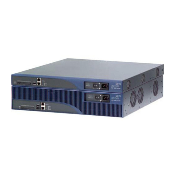
MSR 50-40/50-60 Routers Appearance Front view of MSR 50-40 Figure 1-1 Front panel of the MSR 50-40 (10) (1) CF card LED (2) CF card (3) SIC slot 1 (4) SIC slot 2 (5) SIC slot 3 (6) SIC slot 4 (7) FIC slot 5 (8) FIC slot 6 (9) FIC slot 7... - Page 14 Figure 1-3 Front panel of the MSR 50-60 (1) (2) (9) (11) (10) (12) (1) CF card LED (2) CF card (3) SIC slot 1 (4) SIC slot 2 (5) SIC slot 3 (6) SIC slot 4 (7) FIC slot 5 (8) FIC slot 6 (9) FIC slot 7 (10) FIC slot 8...
-
Page 15: Generic Modules
Generic Modules The MSR 50 series is available with the generic modules as power modules, SICs and interface modules. Currently, it primarily supports the main board MPUF. See details as follows. MPUF Functions As the core of the router, the MPUF functions to process protocols, forward low-speed packets, govern interfaces, and detect faults. - Page 16 Specifications Table 1-5 MPUF specifications Item Specifications 2 10/100/1000 Mbps Ethernet COMBO interfaces 1 AUX port Interfaces 1 console port 2 USB interfaces Processor 833 MHz BootROM 4 MB Default: 512 MB DDR SDRAM Max: 1 GB Default: 256 MB CF Card Max: 1 GB Slot...
- Page 17 Figure 1-8 Big view of LEDs and interfaces ( 9 ) (10) (11) (14) (19) (18) (24) (16) (13) (22) (12) (23) (15) (21) (20) (17) (25) (1) System LED (SYS) (2) Fan LED (FAN) (3) Power LED 1 (PWR1) (4) Power LED 0 (PWR0) (5) VPM LED 3 (VPM3) (6) VPM LED 2 (VPM2)
- Page 18 Color Number Status Meaning The FAN module is not present. Green & The FAN module is working Steady green yellow normally. Yellow The FAN module has failed. VPMx is not present. Green & Steady green VPMx is present, yellow Yellow VPMx has failed.
- Page 19 Color Number Status Meaning No connection is established. 1000 Mbps connection is Green established. Active. GE0/1 is transmitting or Green & Green, blinking GE0/1 receiving data. yellow 10/100 Mbps connection is Yellow established. Active. GE0/1 is transmitting or Yellow, blinking receiving data.
- Page 20 The attributes are listed in the following table: Table 1-9 1000 Mbps Ethernet electrical interface attributes Attribute Description Connector RJ-45 Interface MDI/MDIX auto-sensing Ethernet_II Frame format Ethernet_SNAP 10/100/1000 Mbps auto-sensing Operating mode Full duplex/half duplex (1000 Mbps and half duplex cannot be configured together.) Table 1-10 1000 Mbps Ethernet optical interface attributes Description Single-mod...
-
Page 21: Msca
Compact Flash (CF) slot The MPUF provides one CF (PCMCIA) slot for a hot swappable CF card. A CF card can store application programs, configuration files, and log information. With it, you can conveniently perform such operations as online upgrade and log management. Do not remove a CF card during its read or write operation;... -
Page 22: Psu
MSCA (Multi-Service Card A) is back main control board of MSR 50 series to carry various service modules. ESM module Installed on MSCA, ESM module supports IPSec and by using hardware encryption expedites IP packet encryption. The use of hardware encryption/decryption and hashing operation allows the router to encrypt packets with high performance and reliability. -
Page 23: Fan Module
You can connect a PSU to the backplane by inserting it from the rear of the router chassis. It is hot swappable and its switchover does not affect the ongoing system operation. When installing your router in a communications equipment room, ensure that the AC power distribution cabinet can provide a lightning protection box or arrester against the current of 20 KA and above. -
Page 24: Sic/Dsic And Fic/Dfic Interface Cards
threshold, the fans are rotating only at half of the speed (50%). When a fan stops rotating, the fan controller alarms. The alarm and state LEDs of the FAN are located on the front panel of MPUF. Appearance The following figure shows a FAN module, taking MSR 50-60 for example. Figure 1-13 FAN module (the MSR 50-60) SIC/DSIC and FIC/DFIC Interface Cards MSR 50 series routers adopt modular design and support a wide range of optional SIC/DSIC and... -
Page 25: Voice Module
Table 1-14 Encryption card attributes Attribute Description Protocol IPsec Key algorithms: DES, 3DES, AES Hardware encryption algorithm Authentication algorithms: HMAC-MD5-96, HMAC-SHA-1-96 Voice Module VPM (Voice Processing Module) functions to implement the encryption/decryption, EC and CNG of voices. VCPM (Voice Co-Processing Module) processes the voice data together with VPM. Voice co-processing module (RT-VCPM) 8-channel voice processing module (RT-VPM8) 16-channel voice processing module (RT-VPM16) - Page 26 Table of Contents 2 Installation Preparations···························································································································2-1 Requirements on Environment ···············································································································2-1 Requirements on Temperature/Humidity ························································································2-1 Requirements on Cleanness ···········································································································2-1 Requirements on Electrostatic Discharge Prevention·····································································2-2 Requirements on Electromagnetic Environments ···········································································2-2 Requirements on Preventing Lightning ···························································································2-3 Requirements on Workbench··········································································································2-3 Safety Precautions ··································································································································2-3 Installation Tools, Meters and Equipments ·····························································································2-4...
-
Page 27: Installation Preparations
Installation Preparations Requirements on Environment MSR 50 Series must be used indoors. To ensure the normal operation and prolong their service life, the following requirements for installation site must be met. Requirements on Temperature/Humidity To ensure the normal operation and prolong their service life, certain requirements on temperature and humidity in the equipment room shall be met. -
Page 28: Requirements On Electrostatic Discharge Prevention
Besides the dust specifications, the equipment room of the Router should also meet the rigorous requirements for the content of salt, acid and sulfide. These harmful gases could accelerate the metal erosion and aging process of some parts. The specific limits of these harmful gases as SO S, NO and CI are given in the following table. -
Page 29: Requirements On Preventing Lightning
Requirements on Preventing Lightning Although many measures have been taken to protect MSR 50 Series from lightning, if the lightning intensity exceeds a certain range, damage to the router may still happen. To protect the router from lightning better, the following should be considered: Ensure the PGND wire of the chassis is well grounded. -
Page 30: Installation Tools, Meters And Equipments
Installation Tools, Meters and Equipments Tools Phillips screwdriver Straight screwdriver ESD-preventive twist strap Cables PGND wire and power cord Console cable Optional cables Meters and equipment Hub or LAN switch Console terminal (it could be a PC) Equipment related to the selected modules Multimeter MSR 50 series was not shipped with any installation tools, meters, or devices. - Page 31 Table of Contents 3 Installation··················································································································································3-1 Installation Process ·································································································································3-1 Installing the Cabinet·······························································································································3-2 Installing the Router ································································································································3-2 Installing the Router on a Workbench ·····························································································3-2 Installing the Router in a Rack ········································································································3-2 Installing Generic Modules······················································································································3-3 Connecting the PGND·····························································································································3-3 Connecting the Power Cord····················································································································3-4 Power Input and PGND ···················································································································3-4 Connecting the AC Power Cord ······································································································3-4 Connecting the DC Power Cord ······································································································3-5 Connecting the Console Terminal···········································································································3-6...
-
Page 32: Installation
Installation Installation Process Figure 3-1 MSR 50 Series Routers installation process Start Mount the rack Connect PGND Connect the power cord Connect to the c onsole terminal V erif y installation Pow er on Troubleshoot Turn off the Normal? pow er s w itc h Turn of f the pow er sw itch Install the FICs... -
Page 33: Installing The Cabinet
Installing the Cabinet For the cabinet installation, refer to MSR Series Routers Cabinet Installation Manual If you install the router not in a cabinet or install it in a cabinet from other manufacturers, you can skip this process. Installing the Router Install the router after you have completed the installation preparations. -
Page 34: Installing Generic Modules
Figure 3-2 Installing MSR 50 Series Router in a rack (1) Mounting ear (2) Guide Installing Generic Modules Installing generic modules includes installing the main control board, PSUs, the FAN module, and FICs. For more information about the main control board, PSUs, FAN module and their installation, refer to Chapter 6 “Hardware Maintenance”... -
Page 35: Connecting The Power Cord
Figure 3-3 PGND screw of the router Use a PGND cable to connect the screw to the earth ground, and the grounding resistance should not be greater than 5-ohm. Likewise, if the router is installed in a 19-inch standard rack, this rack is required to be grounded too. -
Page 36: Connecting The Dc Power Cord
Figure 3-4 Power socket on AC-powered units (1) Power switch (2) AC input AC power socket (recommended) You are recommended to use a three-terminal single-phase power socket with ground contact, which must be grounded reliably. Normally, the ground contact of the power supply system in a building was buried during construction and cabling. -
Page 37: Connecting The Console Terminal
Connecting the DC power cord Figure 3-6 Sketch map of DC power cord Table 3-3 Connection of the DC power cord between the DC power supply and the router –48 VDC power supply Router X2 (–48 VDC connector, blue) X1.A1 X3 (BGND connector, black) X1.A3 Step 1: Make sure that the PGND is properly grounded to the earth. -
Page 38: Fixed Interfaces
Console cable Console cable is an eight-wire shielded cable. At one end of the cable is a crimped RJ-45 connector to the console port on the router; at the other end of the cable is a DB-9 (female) connector to the serial port on the console terminal. - Page 39 Table 3-6 1000 Mbps Ethernet optical interface attributes Description Single-mode Multi-mode Single-mode Single-mode Single-mode Attribute ultra-long short-haul medium-hau long-haul long-haul haul (1550 (850 nm) l (1310 nm) (1310 nm) (1550 nm) Connector SFP/LC 62.5/125 μm 9/125 μm 9/125 μm 9/125 μm 9/125 μm Optical fiber multi-mode...
- Page 40 Figure 3-8 Ethernet cable Ethernet cables fit into the following two categories: Standard cable, also called straight-through cable, at both ends of which, wires are crimped in the RJ-45 connectors in the same sequence. The cable connects different categories of devices, such as a terminal device (PC for example) or router to a Hub or LAN switch.
-
Page 41: Connecting Aux To A Modem
For a 10/100/1000 Mbps port, connect it to a PC or another router using a crossover cable or to a Hub or LAN switch using a straight-through cable. Step 2: View the LINK LED of the Ethernet interface: ON means a link is present. OFF means no link is present;... -
Page 42: Interface Card Module
Figure 3-9 AUX cable Connecting the AUX cable Follow these steps to connect the AUX cable. Step 1: Plug the RJ-45 connector of the cable into the AUX port on the main control board. Step 2: Plug the DB-25 or DB-9 connector into the serial port on the analog modem. When using the AUX interface for remote configuration or dial backup, you need to connect the local modem to the remote modem through PSTN and then to the remote device. -
Page 43: Installing Slide Rail
FIC slide rail Figure 3-11 FIC slide rail Installing Slide Rail Figure 3-12 Install an FIC slide rail Figure 3-13 Installation finished 3-12... -
Page 44: Removing Slide Rail
The design of demountable slide rail greatly facilitates users to extend their services. The slide rail is fixed on chassis through special structure. When you need to install a DFIC, you only need to uninstall the rail and install the module. The rail may deviate out of external force when you install a DFIC, thus the DFIC on the other side cannot be installed normally. -
Page 45: Verifying Installation
Verifying Installation During router installation, you must verify installation each time you power on the router, making sure that: There is enough space around the router for heat-dissipation, and the workbench is stable enough. The power supply that the power cord connects to is compliant with that required by the router. The PGND wire of the router is correctly connected. - Page 46 Table of Contents 4 Startup and Configuration ························································································································4-1 Startup·····················································································································································4-1 Setting up Configuration Environment·····························································································4-1 Powering on the Router···················································································································4-3 Startup Process ·······························································································································4-4 Configuration Fundamentals···················································································································4-5 Basic Configuration Procedures······································································································4-6 Command Line Interface ·················································································································4-6 Arranging Slots and Numbering Interfaces ·····················································································4-7...
-
Page 47: Startup And Configuration
Startup and Configuration Startup You can only configure the router through the console port if it is the first time you use it. Setting up Configuration Environment Connecting the router to a console terminal To set up the local configuration environment, RJ-45 connector of the console cable needs to be connected to the console port on the router, and DB-9 connector to the serial interface of a PC, as shown in the following figure. - Page 48 Figure 4-2 Local configuration connection interface Setting serial interface parameters. As shown in Figure 4-3, in the properties dialog box of the serial interface, set the baud rate to 9600, data bit to 8, no parity check, stop bit to 1, and flow control to none.
-
Page 49: Powering On The Router
Figure 4-4 Set terminal type Powering on the Router Checking before power-on Check according to the following items before powering on the router. Whether the power cord and PGND wire are correctly connected. Whether the voltage of the power supply complies with the requirement of the router. Whether the console cable is correctly connected, whether the PC or terminal for configuration is open, and whether the settings are done. -
Page 50: Startup Process
After completing the power-on self-test (POST), the system asks you to press <Enter>. When the prompt appears, you may proceed to configure the router. Startup Process After being powered on and reboot, the router initializes the memory first: InitDDR The system runs the BootROM program when finishing initialization, and then prompts as follows: system start booting..Version 2.11 Press CTRL+D to stop auto-boot9... -
Page 51: Configuration Fundamentals
cf:/ - Volume is OK Mount CF Card OK! CF Card Size:256MBytes Press Ctrl+B to enter extended boot menu... Enter <Ctrl+B>, and the system enters the extended BootROM menu; otherwise, the system enters the program decompression process. The system enters the Boot extended menu only if <Ctrl+B> is pressed immediately (within six seconds) after the statement “Press Ctrl+B to enter extended Boot Menu...”... -
Page 52: Basic Configuration Procedures
Step 1: Before configuring the router, the networking requirements should be made specific, which include networking purpose, the role of the router in the network, the division of subnets, WAN type and transmission medium, the network security policy and reliability. Step 2: Based on the above requirements, draw a clear and integrated networking diagram. -
Page 53: Arranging Slots And Numbering Interfaces
Arranging Slots and Numbering Interfaces Slot arrangement The MSR 50 series provides many types of interfaces, such as Console, AUX, Ethernet, serial (synchronous/asynchronous), and asynchronous port. The following describes how these interfaces are numbered. Figure 4-5 Slot arrangement on the MSR 50-40 (1) Slot 0 (2) Slot 1 (3) Slot 2... - Page 54 The interfaces are represented by interface-type X/Y, where interface-type can be serial, asynchronous, Ethernet, ATM, and so on; X specifies the slot number; and Y specifies the interface sequence. Different interfaces on an interface module share the same slot number X. For every interface, Y starts from 0, indicating the interface sequence on the interface module, from left to right.
- Page 55 Table of Contents 5 Software Maintenance·······························································································································5-1 Introduction ·············································································································································5-1 Files ·················································································································································5-1 Software Maintenance Methods······································································································5-3 BootROM Menu ······································································································································5-4 Main BootROM Menu ······················································································································5-4 BootROM Submenus·······················································································································5-6 Upgrading BootROM Through Serial Port ······························································································5-8 Modifying Serial Port Parameters····································································································5-9 Upgrading BootROM ·····················································································································5-11 Upgrading Application Program Through Serial Port············································································5-12 Upgrading Application Program Through Ethernet Interface································································5-12 Configuring Ethernet Parameters··································································································5-12 Upgrading Application Program Through Ethernet Interface ························································5-14...
-
Page 56: Software Maintenance
Software Maintenance Introduction Files BootROM program file The file is used for booting application at boot. A complete BootROM file includes two segments: basic and extended. Application program file The router is available with Dual Image function. By default, the system defines and attempts to boot in order with three boot files: main, backup, and secure, provided they are available with CF card. - Page 57 Configuration file The file stores configuration information of the router. By default, the system defines and attempts to boot in order with three configuration files: main, backup, and default, provided they are available with CF card. If the router fails to boot with the secure boot file, it prompts the boot failure.
-
Page 58: Software Maintenance Methods
The file name cannot be longer than 64 characters (including drive letter and a string terminator. If the drive letter is “CF:/”, the file name can be at most [ 64-1-4 ] = 59 characters in length; or, errors will occur in file operation. Typically, the file name is recommended to be not more than 16 characters. -
Page 59: Bootrom Menu
Figure 5-1 Upgrade BootROM and Comware under Comware V5 environment Start Comware version Upgrade Comware ? Choose correct Comware Choose upgrade mode Via network interface Xmodem upgrade TFTP upgrade upgrade Upgrade BootROM Menu Main BootROM Menu When the router is powered on and reboots, the console terminal displays: InitDDR Proceed to boot, and the system prompts: system start booting..Version... - Page 60 ******************************************************* Copyright(c) 2004-2007 Compiled date: Apr 09 2007, 08:52:28 CPU type : MPC8541 CPU L1 Cache : 32KB CPU L2 Cache : 256KB CPU Clock Speed : 833MHz Memory Type : DDR SDRAM Memory Size : 512MB Memory Speed : 333MHz BootRom Size : 4096KB CPLD...
-
Page 61: Bootrom Submenus
Table 5-3 Main BootROM menu Menu item Description <1> Boot From CF Card Boot from the CF card. Enter serial submenu. Refer to section “Enter serial <2> Enter Serial SubMenu submenu” for details. Enter Ethernet submenu. Refer to section “Enter <3>... - Page 62 Menu item Description <5> Modify Serial Interface Parameter Modify serial interface parameter. <6> Exit To Main Menu Exit to the main menu. Enter Ethernet interface submenu Enter <3> in BootROM menu to enter the Ethernet interface submenu. The system displays: ====================<ETHERNET SUB-MENU>====================== |Note:the operating device is CF Card | <1>...
-
Page 63: Upgrading Bootrom Through Serial Port
The submenu is defined as follows: Table 5-6 File control submenu Menu item Description <1> Display All File Display all files. <2> Set Application File type Set application file type. <3> Set Configuration File type Set configuration file type. <4> Delete File Delete files. -
Page 64: Modifying Serial Port Parameters
Modifying Serial Port Parameters Sometimes, we need to change the serial baud rate to higher in order to save upgrading time, or to lower to guarantee transmission reliability. This section depicts how to adjust serial baud rate. Enter <2> under the main BootROM menu to enter the serial submenu. Then, enter <5>, and the system prompts to change serial baud rate. - Page 65 Figure 5-3 Modify baud rate Click [Call/Call] to establish new connection. Figure 5-4 Establish new connection Then, press <Enter> to prompt current configuration baud rate and return to the previous menu. The system prompts: The current baudrate is 115200 Restore the baud rate in the HyperTerminal to 9600 bps (the default) after upgrading the BootROM. This is to ensure that information can be displayed on the console screen after system boot or reboot.
-
Page 66: Upgrading Bootrom
Upgrading BootROM First, enter <7> under the main BootROM menu (refer to section “Main BootROM Menu”) to enter the BootROM operation submenu, under which all BootROM operations are completed. Refer to section “BootROM operation submenu” for detailed descriptions. For example, when you upgrade full BootROM: First, change serial baud rate to speed up upgrading (refer to section “Modifying Serial Port Parameters”... -
Page 67: Upgrading Application Program Through Serial Port
Change the baud rate of the console terminal from 115200 bps to 9600 bps, and then reboot the router. The file name, size and path vary in different situations. Check the current version of BootROM and application program in order to use correct file. This method only upgrades a part of BootROM. - Page 68 '.' = clear field; '-' = go to previous field; Ctrl+D = quit boot device : mottsec0 processor number host name : host file name : main.bin inet on ethernet (e) : 192.168.80.10 inet on backplane (b): host inet (h) : 192.168.80.200 gateway inet (g) user (u)
-
Page 69: Upgrading Application Program Through Ethernet Interface
When configuring parameters, enter new parameters directly; or press <ENTER> to accept the default parameter coming after the colon, “.” for “clear field”, “-” for “go to previous filed", and “Ctrl+D” for “quit”. Upon upgrade failure, the system prompts “Loading failed”. In this case, please reboot the router to validate the reset IP address. - Page 70 Loading... Done! 14323376 bytes downloaded. Input the File Name: After the download is done, input the file name and begin to update: Updating File main.bin..Update Success! Step 4: Enter <6> to exit to the main BootROM menu. Enter <1> to boot from the CF card. Step 5: Set the updated application program to be the main boot file, i.e.
-
Page 71: Maintaining Application Program And Configuring Through Command Lines
Modify this file Attribute: +Main -Main +Backup -Backup Exit Enter your choice(1-5):1 Enter "1" to set the selected application program to be the main boot file, i.e. the default boot file of the system. Step 6: Enter <5> to exit to the main BootROM menu. Enter <1> to boot from the CF card. The file in the CF card will be overwritten if the file name being input is the same as the original file name in the CF card. - Page 72 Figure 5-8 Networking diagram for maintenance under command line mode Ethernet Console ROUTER (TFTP/FTP Server) (TFTP/FTP Client) Configure the IP addresses of the two sides to be in the same network. In this section, the TFTP server is set to 192.168.0.1, and the Ethernet interface connected to it (Ethernet interface 0/0 in this example; so, any interface is OK) is set to 192.168.0.2.
-
Page 73: Maintaining The Router With Ftp Server
TFTP: 1045 bytes received in 0 second(s) File downloaded successfully. If a config.cfg file already exists in the router, select <Y/y> to overwrite it. If a config.cfg file already exists on the server, it will be overwritten. The above operations are performed under user view. The backup configuration file can be modified by text editor. - Page 74 executes accordingly and returns the result of the execution to user. Use the following command to boot the FTP service: [DEVICE]ftp server enable % Start FTP server Add FTP authorized user name and password: [DEVICE]local-user guest [DEVICE-luser- guest]service-type ftp [DEVICE-luser- guest]password simple 123456 Step 3: Maintain the router.
- Page 75 Step 2: Maintain the router through the terminal connected to the console port as follow: <DEVICE> ftp 192.168.0.1 Trying 192.168.0.1 ... Press CTRL+K to abort Connected to 192.168.0.1. 220 3Com 3CDaemon FTP Server Version 2.0 User(192.168.0.1:(none)):guest 331 User name ok, need password Password: 230 User logged in [ftp] Use the command as follows to maintain the router.
-
Page 76: Maintaining Application Program And Configuration File
Maintaining Application Program and Configuration File You can modify and display the file type under the file control submenu: Enter <4> under the main BootROM menu to enter the file control submenu. The system prompts: ========================<File CONTROL>======================= |Note:the operating device is CF Card | <1>... - Page 77 -Backup Exit Enter your choice(1-5): You can set the file type to +M, -M, +B and -B by entering 1 to 4. Refer to section “Introduction” for details. Set configuration file type Enter <3> under the file control submenu to enter the configuration file type menu. Please set configuration file type in cf: M=MAIN...
-
Page 78: Dealing With Router Password Loss
deleting... success! Confirm the file to be deleted before deleting since the system does not prompt you to confirm when deleting files. Exit to the main menu Exit to the main BootROM menu. Dealing with Router Password Loss Do as follows when your BootROM password, user password or Super Password is lost. User Password Loss You cannot enter the system if you lose your user password. -
Page 79: Bootrom Password Loss
Step 4: Save the new configuration. [DEVICE] save Execute the save command after modifying the user password to save the new password. BootROM Password Loss Contact the agent or our technical support personnel in the event of BootROM password loss. They can help you set a new password. - Page 80 Now, the entire BootROM is backed up to the memory. Enter <2> under the menu to restore the BootROM in the memory to the system: Restore Basic BootRom Updating the Norm Basic BootRom....Restore Basic Bootrom Success! Restore Extend BootRom Updating Extended BootRom....
- Page 81 Table of Contents 6 Hardware Maintenance ·····························································································································6-1 Preparing Tools·······································································································································6-1 Internal Structure·····································································································································6-1 Removing/Installing PSUs ······················································································································6-3 Removing a PSU ·····························································································································6-3 Installing a PSU ·······························································································································6-3 Removing/Installing the Fan Module·······································································································6-3 Removing the Fan Module ··············································································································6-4 Installing the Fan Module ················································································································6-4 Removing/Installing the MPUF ···············································································································6-4 Removing the MPUF ·······················································································································6-5 Installing the MPUF ·························································································································6-5 Removing/Installing MSCA ·····················································································································6-6...
-
Page 82: Hardware Maintenance
Hardware Maintenance Preparing Tools Phillips screwdriver Straight screwdriver ESD-preventive twist strap Static shielding bag The tools are not available with the MSR 50 series. You must prepare one yourself. Internal Structure Figure 6-1 Internal structure (1) Power and SIC slot (2) MPUF and interface card slot (3) Fan slot... - Page 83 Figure 6-2 MPUF internal structure (1) Memory bar slot (2) SIC slot (3) CF card slot Figure 6-3 MSCA internal structure (1) VPM slot (2) VCPM slot (3) ESM slot 1 (4) ESM slot 0...
-
Page 84: Removing/Installing Psus
Removing/Installing PSUs Removing a PSU Figure 6-4 Remove a PSU Step 1: Remove the power cord connected to the PSU and loosen the two captive screws fastening the module panel. Step 2: Hold the handle of the PSU and gently pull it out along the guides. If you do not plan to replace the PSU soon, install a blank filler panel to ensure adequate ventilation and prevent dust. -
Page 85: Removing The Fan Module
Removing the Fan Module Figure 6-5 Remove a fan module Step 1: Loosen the two captive screws on the fan module. Step 2: Hold the handle on the fan module with one hand and its bottom with the other hand. Pull part of the fan module out. -
Page 86: Removing The Mpuf
Removing the MPUF Figure 6-6 Loosen the captive screw of MPUF Figure 6-7 Remove the MPUF Step 1: Turn off the power switch (or switches if two PSUs are installed). Step 2: Loosen the captive screws at both sides of the MPUF. Step 3: Pull the handles at both side of the MPUF outward and gently pull the card out along the guides until it is completely separated from the chassis. -
Page 87: Removing/Installing Msca
Step 4: Power on the router and check that the SYS LED is blinking in green. Removing/Installing MSCA Removing MSCA Figure 6-8 Remove an MSCA Step 1: Turn off the power switch (or switches if two PSUs are installed). Step 2: Loosen the captive screws at both sides of the MSCA. Step 3: Pull the handles at both side of the MSCA outward and gently pull the card out along the guides until it is completely separated from the chassis. -
Page 88: Installing Cf Card
Installing CF Card Figure 6-10 Press the CF card into the slot Install the CF card following these steps: Step 1: Push the spring button into the slot completely, and make sure it only springs out with outside force. Step 2: Press the CF card into the slot in correct orientation, and make sure it only springs out with outside force. -
Page 89: Replacing Memory Bar
Do not insert or remove the card when the router is booting or the LED is blinking to avoid hardware damage. Replacing Memory Bar This section describes how to replace a memory bar. See the following flow. Figure 6-12 Memory bar maintenance flow Start Start Prepare tools... -
Page 90: Memory Bar Structure
Memory Bar Structure Figure 6-13 Memory bar structure Memory Bar Slot Figure 6-14 MPUF memory bar slot Installing/Removing Memory Bar Follow the steps below to install the memory bar: Step 1: Make sure all power interfaces are shut down, and then proceed. Step 2: Align the memory bar golden finger with the slot on the main board. -
Page 91: Replacing Vpm
Figure 6-15 Install memory bar into the slot Follow the steps below to remove the memory bar: Step 1: Make sure all power interfaces are shut down, and then proceed. Step 2: Press the spring clips on the two sides of the memory bar, and pull outwards levelly until the memory bar separates with the spring clips and forms an angle of 45 degrees with the main board. -
Page 92: Vpm Slot
VPM Slot Figure 6-18 VPM slot Installing/Removing VPM Follow the steps below to install the VPM: Step 1: Make sure all power interfaces are shut down, and then proceed. Step 2: Align the VPM golden finger with the slot on the main board. Step 3: Insert the VPM vertically into the slot. - Page 93 Figure 6-20 Fix the base Figure 6-21 Fasten the card on the base with screws Perform the steps inversely to remove the card. 6-12...
-
Page 94: Troubleshooting
Table of Contents 7 Troubleshooting ········································································································································7-1 Troubleshooting the Power System ········································································································7-1 Troubleshooting the Configuration System·····························································································7-1 Troubleshooting Application Software Upgrade ·····················································································7-2... -
Page 95: Troubleshooting
Troubleshooting Troubleshooting the Power System Symptom: The PWR LED RUN is OFF or blinking. Solution: Check that: The power switch on the router is turned on. The switch of the power source is turned on. The power cord is correctly connected. The power source meets the requirement of the router. -
Page 96: Troubleshooting Application Software Upgrade
Troubleshooting Application Software Upgrade Symptom 1: When upgrading the Comware software using TFTP, the system displays: boot device : mottsec unit number processor number file name : main.bin inet on ethernet (e) : 192.168.0.2 host inet (h) : 192.168.0.1 user (u) : guest ftp password (pw) : 123456... - Page 97 The bar code labels on the chassis and the FICs contain information about production and servicing. Before you ask your agent for servicing, provide its bar code. The system does not display the host name and gateway parameters when upgrading if you did not set them.