
Related Manuals for 3Com 3CBLUG24A


Summary of Contents for 3Com 3CBLUG24A
-
Page 1: User Guide
3Com Baseline Switch 2816(3CBLUG16A) 3Com Baseline Switch 2824(3CBLUG24A) User Guide Manual Version: 6PW103 www.3com.com 3Com Corporation 350 Campus Drive, Marlborough, MA, USA 01752 3064... - Page 2 3Com Corporation. 3Com Corporation reserves the right to revise this documentation and to make changes in content from time to time without obligation on the part of 3Com Corporation to provide notification of such revision or change. 3Com Corporation provides this documentation without warranty, term, or condition...
- Page 3 Improving our environmental record on a continual basis. End of Life Statement 3Com processes allow for the recovery, reclamation and safe disposal of all end-of-life electronic components. Regulated Materials Statement 3Com products do not contain any hazardous or ozone-depleting material.
-
Page 4: About This Manual
About This Manual Organization 3Com Switch 2816/2824 User Guide is organized as follows: Chapter Contents Introduces the hardware features, 1 Product Overview LEDs, and network design of the switch. 2 Installing the Switch Introduces how to install the switch. Introduces how to solve some common 3 Problem Solving problems of the switch. -
Page 5: Obtaining Documentation
Obtaining Documentation You can access the most up-to-date 3Com product documentation on the World Wide Web at this URL: http://www.3com.com. -
Page 6: Table Of Contents
Table of Contents 1 Product Overview ..................1 Introduction....................1 Summary of Hardware Features ............1 Physical Features.................. 4 Front Panel ..................4 Rear Panel..................4 Description of LEDs ................4 Technical Specifications................ 5 Network Design ..................7 2 Installing the Switch ................9 Package Contents ................10 Positioning the Switch .................10 Rack Mounting ..................12 Powering On..................13... - Page 7 ICES Statement ................31 VCCI Statement................32 CCC Statement................32 Appendix C - Collection List of the Hazardous Substances ....33...
-
Page 8: Product Overview
Product Overview Introduction The 3Com Baseline Switch 2824 and the 3Com Baseline Switch 2816 are versatile, easy-to-use, unmanaged gigabit switches. It is ideal for users who want the high-speed performance of 10/100/1000 switching but do not need sophisticated management functions. The Switch is shipped ready for use, and operational straight out of the box. - Page 9 Table 1-1 Hardware Features Feature Description Auto-negotiation Supported on all ports. Forwarding Modes Store and Forward. Mac Address Table 2816: 32Gbps Port throughput 2824: 48Gbps Auto MDI/MDIX Supported on all ports. The Switch offers priority queuing, which means all packets that are received are examined to see if they have been priority encoded.
-
Page 10: Feature Description
Feature Description The Switch has 24/16 10/100/1000 Mbps auto-negotiating ports. Each port automatically negotiates with the attached device to determine the correct speed and duplex mode of operation. Once negotiated, the port will operate in one of the following modes: 10BASE-T half duplex 10BASE-T full duplex 100BASE-TX half duplex... -
Page 11: Physical Features
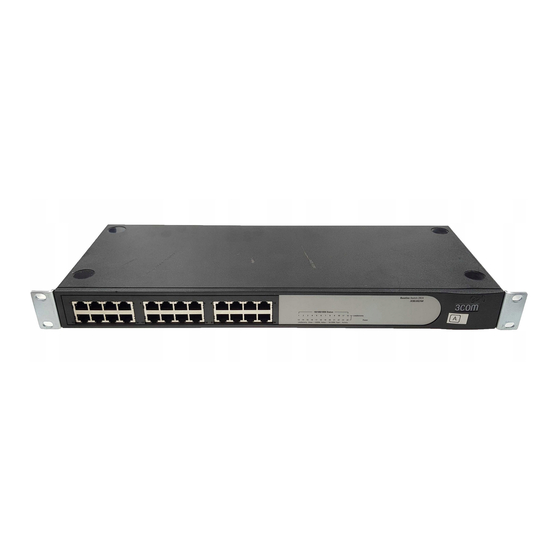
Physical Features Front Panel Figure 1-2 2816 Figure 1-3 2824 Rear Panel Figure 1-4 Rear Panel Description of LEDs The Switch provides LEDs on the front panel for your convenience to monitor the switch. Table 1-2 describes the meanings of the LEDs. -
Page 12: Technical Specifications
Table 1-2 Description on the LEDs of the Switch Status Description The unit is powered on and ready for Green use. The unit is not receiving power: Power Check that the power cord is connected correctly. If the unit still does not operate, contact your supplier. - Page 13 Table 1-3 Technical specifications of the Switch. Specification 2816 2824 44 mm×440 44 mm×440 Physical mm×173 mm mm×173 mm dimensions (1.73 × 17.32 × (1.73 × 17.32 (H×W×D) 6.81 in.) × 6.81 in.) <1.65 kg(3.64 <1.75 kg(3.86 Weight Physical Ethernet port quantity Free standing, or 19-inch rack Mounting...
-
Page 14: Network Design
Specification 2816 2824 SO 8802-3, IEEE 802.3 (Ethernet), IEEE 802.3u (Fast Ethernet), IEEE 802.3ab (Gigabit Functional Ethernet), IEEE 802.3x(Flow control on full duplex links), IEEE 802.3d(Bridging), IEEE 802.1 p (VLAN tagging/ priority queuing) Related UL 60950-1, IEC60950-1, CSA Safety Standards 22.2 #60950-1, EN 60950-1 EN 55022 Class A, FCC Part 15 Subpart B Class A, ICES-003... - Page 15 Figure 1-5 Network Design...
-
Page 16: Installing The Switch
Installing the Switch WARNING: Safety Information. Before you install or remove any components from the Switch or carry out any maintenance procedures, you must read the safety information in Appendix A: Safety Information in this guide. AVERTISSEMENT: Consignes de sécurité. Avant d'installer ou d'enlever tout composant de Switch ou d'entamer une procédure de maintenance, lisez les informations relatives à... -
Page 17: Package Contents
OSTRZEŻENIE: Informacje o zabezpieczeniach. Przed instalacją lub usunięciem jakichkolwiek elementów z product lub przeprowadzeniem prac konserwacyjnych należy zapoznać się z informacjami o bezpieczeństwie zawartymi w Załączniku A niniejszego podręcznika. ADVERTÊNCIA: Informações de segurança Antes de instalar ou remover quaisquer componentes do Switch ou de executar quaisquer procedimentos de manutenção, leia as informações de segurança no Appendix A: Safety Information deste guia. - Page 18 Water or moisture cannot enter the case of the switch. Air flow is not restricted around the switch or through the vents in the side of the switch. 3Com recommends that you provide a minimum of 25 mm (1 in.) clearance.
-
Page 19: Rack Mounting
The AC supply used by the switch is separate from that used by units that generate high levels of AC noise, for example air conditioning units. No more than four switch units are placed on top of one another, if the units are free-standing. Rack Mounting The Switch is 1U high and fits in most standard 19-inch racks. -
Page 20: Powering On
Figure 2-1 Fitting a front bracket for rack-mounting You must use the screws supplied with the securing brackets. Damage caused to the unit by using incorrect screws invalidates your warranty. 4) Repeat steps 2 and 3 for the other side of the switch. 5) Insert the switch into the 19-inch rack and secure with suitable screws. - Page 21 3) Connect the plug to the power supply outlet socket and switch on the power supply at the socket.
-
Page 22: Problem Solving
Problem Solving At regular intervals you should visually check the Switch. Regular checks can give you an early warning of a possible failure. Check that all external cabling connections are secure and that no cables are pulled taut. Refer to the information about LEDs given earlier in this guide to see if the problem can be identified and solved. - Page 23 Product number and serial number (printed on a label supplied with the unit). A brief description of the fault condition.
-
Page 24: Appendix A - Safety Information
Appendix A - Safety Information Important Safety Information Please read the following safety information carefully before installing the Switch. If installing the Switch unit in a stack with other Baseline units, the Switch must be installed below the narrower Hub units. The unit must be earthed (grounded). - Page 25 Connect only RJ-45 data connectors, network telephony systems, or network telephones to these sockets. Either shielded or unshielded data cables with shielded or unshielded jacks can be connected to these data sockets. Power Cord Set: The power cord set must be approved for the country where it is used: The cord set must be UL-approved and CSA certified.
-
Page 26: L'information De Sécurité Importante
L’information de Sécurité Importante Si vous entassez l’unité Switch avec les unités Baseline, l’unité Switch doit être installée en dessous des unités Hub plus étroites. Vous devez mettre l’appareil à la terre (à la masse) ce groupe. Brancher l’unité à une source de courant mise à laterre pour assurer la conformité... -
Page 27: Wichtige Sicherheitsinformationen
107-2 D1 de la norme DK2 1a ou DK2 La prise mâle d’alimentation doit respecter la Suisse norme SEV/ASE 1011. Wichtige Sicherheitsinformationen Wenn der Switch mit anderen 3Com Hubs oder Switch gestackt werden soll, müssen grössere Geräte unter den schmaleren Hubs eingebaut werden. - Page 28 Das Gerät muß geerdet sein. Das Gerät muß an eine geerdete Steckdose angeschlossen werden, die europäischen Sicherheitsnormen erfüllt. Der Anschlußkabelsatz muß mit den Bestimmungen des Landes übereinstimmen, in dem er verwendet werden soll. Der Gerätestecker (der Anschluß an das Gerät, nicht der Wandsteckdosenstecker) muß...
-
Page 29: Información De Seguridad Importante
ungeschützte Buchsen dürfen an diese Datensteckdosen angeschlossen werden. Europe: Das Netzkabel muß vom Typ HO3VVF3GO.75 (Mindestanforderung) sein und die Aufschrift <HAR> oder <BASEC> tragen. Der Netzstecker muß die Norm CEE 7/7 erfüllen (”SCHUKO”). Información de Seguridad Importante Si instala la unidad Switch en una pila con unidades Baseline, el Switch se debe instalar debajo de las unidades Hub más estrechas. - Page 30 † Impédance à la terre Puertos RJ-45. Son conectores de datos RJ-45 blindados. No pueden utilizarse como tomas de teléfono tradicionales estándar ni para conectar la unidad a una central de conmutación PBX tradicional ni a una red telefónica pública. Conecte sólo conectores de datos RJ-45, sistemas de telefonía de red local o teléfonos de red local a estas tomas.
-
Page 31: Importanti Informazioni Di Sicurezza
La toma de alimentación debe cumplir la norma CEE 7/7 ("SCHUKO"). Sólo para El cable de alimentación de red debe tener Europa la marca <HAR> o <BASEC> y ser de tipo H03VVF3G1.0 (mínimo). La toma de alimentación debe cumplir la Dinamarca sección 107-2-D1 de la norma DK2-1a o DK2-5a. - Page 32 † Impédance à la terre Le porte RJ-45 sono prese dati RJ-45 schermate. Non è pertanto possibile utilizzarle come normali prese telefoniche né per collegare l'unità a un PBX (Private Branch Exchange, centralino telefonico privato) o a una rete telefonica pubblica. Collegare a queste porte solo prese dati RJ-45, sistemi di telefonia o telefoni di rete.
-
Page 33: Ważne Informacje O Zabezpieczeniach
La spina di alimentazione deve essere Dinamarca conforme alla sezione 107-2-D1, standard DK2-1a o DK2 La spina di alimentazione deve essere Svizzera conforme SEV/ASE 1011 Ważne Informacje o Zabezpieczeniach Urządzenie musi być uziemione lub musi być podłączone do uziemionego źródła zasilania w celu zapewnienia zgodności z wymogami bezpieczeństwa. - Page 34 jedynie łącza danych RJ-45, sieciowe systemy telefoniczne lub telefony sieciowe. Zarówno osłonięte, jak i nieosłonięte przewody z danymi wraz z osłoniętymi lub nieosłoniętymi wtykami mogą być podłączone do tych gniazd. Zestaw przewodów zasilania: Niezbędna jest zgodność z przepisami kraju, w którym jest stosowany: Zestaw przewodów musi posiadać...
-
Page 35: Informações De Segurança Importantes
Informações de segurança importantes Se for instalar o Switch em uma pilha com unidades mais estreitas do que o próprio Switch, as unidades do Switch devem ser instaladas sob as unidades mais estreitas. A unidade deve estar aterrada. Conectar a unidade a uma fonte de alimentação aterrada para cumprir os padrões de segurança. - Page 36 telefones de rede. Podem ser usados com cabos de dados blindados ou não, com conectores blindados ou não. sobre o conjunto do cabo de alimentação: O cabo de alimentação deve ser aprovado para o país em que é usado: O cabo de alimentação deve ser aprovado pelo UL e certificado pela CSA.
-
Page 37: Appendix B - Regulatory Information
Appendix B - Regulatory Information FCC Statement This equipment has been tested and found to comply with the limits for a Class A digital device, pursuant to part 15 of the FCC rules. These limits are designed to provide reasonable protection against harmful interference when the equipment is operated in a commercial environment. -
Page 38: Ce Statement (Europe)
Washington, DC 20402, Stock No. 004-000-00345-4. In order to meet FCC emissions limits, this equipment must be used only with cables which comply with IEEE 802.3. CE Statement (Europe) EU Representative: 3Com Europe Limited Peoplebuilding 2, Peoplebuilding Estate Maylands Avenue Hemel Hempstead, Hertfordshire HP2 4NW... -
Page 39: Vcci Statement
VCCI Statement CCC Statement 3Com Baseline Switch 2816/2824 符合国标 GB9254(Class A), YD/T993 和 GB4943 的要求。 此为 A 级产品,在生活环境中,该产品可能会造成无线电干扰。在这 种情况下,可能需要用户对其干扰采取切实可行的措施。... -
Page 40: Appendix C - Collection List Of The Hazardous Substances
Appendix C - Collection List of the Hazardous Substances This document contains information required by the People's Republic of China as per their legislation titled "Management Methods for Controlling Pollution by Electronic Information Products". 产品中有毒有害物质清单全集如下表所示。 有毒、有害物质和元素 多溴 多溴代 部件名称 六价铬 铅... - Page 41 有毒、有害物质和元素 多溴 多溴代 部件名称 六价铬 铅 汞 镉 联苯 二本醚 Cr (VI) PBDE CF卡 〇 〇 〇 〇 〇 〇 光模块 〇 〇 〇 〇 〇 〇 〇 〇 〇 〇 硬盘 〇 〇 〇 〇 〇 电源适配器1 〇 〇 〇...
- Page 42 有毒、有害物质和元素 多溴 多溴代 部件名称 六价铬 铅 汞 镉 联苯 二本醚 Cr (VI) PBDE 〇 〇 〇 〇 〇 麦克风 〇 〇 〇 〇 〇 内存条 〇 〇 〇 〇 〇 天线 〇 〇 〇 〇 〇 光模块1 〇 〇 〇 〇...