
Related Manuals for 3Com WL-603


Summary of Contents for 3Com WL-603
- Page 1 Wireless 11n ADSL Firewall Router User Guide WL-603 3CRWDR300A-73 3CRWDR300B-73 http://www.3Com.com/ Part No. 10016794 Rev AA Published July 2008...
- Page 2 3Com Corporation reserves the right to revise this documentation and to make changes in content from time USA 01752-3064 to time without obligation on the part of 3Com Corporation to provide notification of such revision or change. 3Com Corporation provides this documentation without warranty, term, or condition of any kind, either implied or expressed, including, but not limited to, the implied warranties, terms or conditions of merchantability, satisfactory quality, and fitness for a particular purpose.
-
Page 3: Table Of Contents
ONTENTS BOUT UIDE Naming Convention Conventions Feedback About This User Guide Related Documentation NTRODUCING THE OUTER Wireless 11n ADSL Firewall Router Router Advantages Package Contents Minimum System and Component Requirements Physical Features NSTALLING THE OUTER Introduction Safety Information Positioning the Router Using the Rubber Feet Wall Mounting Mounting Instructions for Cement Walls... - Page 4 Macintosh Disabling PPPoE and PPTP Client Software Disabling Web Proxy UNNING THE ETUP Accessing the Router using the 3Com Detect Application Running the 3Com Detect Application Accessing the Setup Wizard Wizard - Change Password Wizard - Time and Time Zone...
- Page 5 Clone MAC address Firewall Special Applications Virtual Servers PC Privileges Schedule Rule URL Filter Advanced Security VLAN Static Routes DDNS SNMP Syslog Proxy ARP QoS Settings Traffic Mapping System Tools Restart Router Configuration Upgrade Time Zone Ping Traceroute DNS Lookup Diagnostic Status and Logs Status...
- Page 6 The Internet Protocol Suite Managing the Router over the Network IP Addresses and Subnet Masks How does a Device Obtain an IP Address and Subnet Mask? DHCP Addressing Static Addressing Auto-IP Addressing ECHNICAL PECIFICATIONS 3Com Wireless 11n Cable/DSL Firewall Router Standards...
- Page 7 AFETY NFORMATION OFTWARE ICENSE BTAINING UPPORT FOR Register Your Product to Gain Service Benefits Solve Problems Online Purchase Extended Warranty and Professional Services Access Software Downloads Contact Us Telephone Technical Support and Repair LOSSARY EGULATORY OTICES NDEX GREEMENT RODUCTS...
-
Page 9: About This Guide
Router for connection to your telephone line. If a release note is shipped with the 3Com Wireless 11n ADSL Firewall Router and contains information that differs from the information in this guide, follow the information in the release note. -
Page 10: Conventions
BOUT UIDE Conventions Table 1 and Table 2 list conventions that are used throughout this guide. Table 1 Notice Icons Table 2 Text Conventions Convention The words “enter” and “type” Keyboard key names Words in italics Icon Notice Type Description Information note Information that describes important features or instructions. -
Page 11: Feedback About This User Guide
Installation Guide. This guide contains the instructions you need to install and configure your Router. Document title Document part number (on the title page) Page number (if appropriate) 3Com Wireless 11n ADSL Firewall Router User Guide Part Number 10016794 Rev. AA Page 24 Feedback About This User Guide... - Page 12 BOUT UIDE...
-
Page 13: Ntroducing The Router
Wireless 11n ADSL The 3Com Wireless 11n ADSL Firewall Router is designed to provide a Firewall Router cost-effective means of sharing a single broadband Internet connection amongst several wired and wireless computers. The Router also provides protection in the form of an electronic “firewall”... - Page 14 1: I HAPTER NTRODUCING THE OUTER Figure 1 Example Network Without a Router When you use the Router in your network (Figure 2 Figure 3), it becomes your connection to the Internet. Connections can be made directly to the Router, or to an OfficeConnect Switch or Hub, expanding the number of computers you can have in your network.
- Page 15 Wireless 11n ADSL Firewall Router Figure 3 Example Network Using a Firewall Router (without splitter)
-
Page 16: Router Advantages
One telephone cable (only for 3CRWDR300A-73 version) One Ethernet cable (Two Ethernet cables in 3CRWDR300B-73 version) One CD-ROM containing this user guide, copies of the quick install guide in various languages and the 3Com Detect application. Installation guide Support and Safety sheet... -
Page 17: Minimum System And Component Requirements
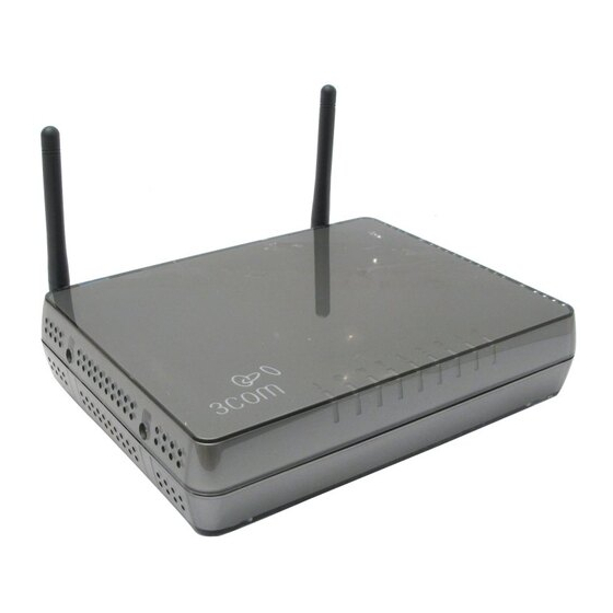
Minimum System Your Router requires that the computer(s) and components in your and Component network be configured with the following: Requirements ■ ■ ■ ■ ■ Physical Features The front panel of the Router contains a series of indicator lights (LEDs) that help describe the state of various networking and connection operations. - Page 18 1 Power LED (Illuminated Logo) White The 3Com logo serves as power OK indicator. This LED will light if the router is receiving power from the power adapter. If it is not lit check the power adapter connections. Refer to...
- Page 19 Physical Features 7 WPS LED Blue WiFi Protected Setup (WPS) is a standard for easy and secure establishment of a wireless network, allowing wireless clients to connect securely to routers and access points. The WPS LED shows the status of the WPS function.
- Page 20 1: I HAPTER NTRODUCING THE The rear panel ports, one WiFi on/off button, a reset button, one power adapter socket, and one WPS button. Figure 5 Router - Rear Panel 1 Wireless Antennae The antennaes should be placed in a ‘V’ position when initially installed. CAUTION: Do not force the antennae beyond their mechanical stops.
- Page 21 4 WiFi On/Off button Use this button to turn on/turn off the wireless function. Press the button for 3 seconds. 5 Reset Button If you want to reset your Router to factory default settings, or cannot access the web management interface (for example, due to a lost password), then you may use this button.
- Page 22 1: I HAPTER NTRODUCING THE OUTER...
-
Page 23: Nstalling The Router
Introduction This chapter will guide you through a basic installation of the Router, including: ■ ■ ■ Safety Information Please note the following: WARNING: Please read the before you start. VORSICHT: Bitte lesen Sie den Abschnitt sorgfältig durch, bevor Sie das Gerät einschalten. AVERTISSEMENT: Veuillez lire attentivement la section importantes de sécurité... -
Page 24: Using The Rubber Feet
Router. Please be careful when you put 3Com 11n ADSL Router on top of another unit, if the unit underneath is hot, this may impact the reliability of 3Com 11n ADSL Router. -
Page 25: Wood Walls
Mounting To wall mount the unit: Instructions for Wood Walls 1 Make two holes 98 mm (3.9 in.) apart. 2 Fix two suitable screws directly into the wall, leaving their heads 3 mm (0.12 in.) clear of the wall surface. The screws should be at least 20 mm (0.75 in.) long. - Page 26 2: I HAPTER NSTALLING THE OUTER Figure 6 Connecting the Router (with splitter) Figure 7 Connecting the Router (without splitter) 1 Run the provided telephone cable from the wall jack providing ADSL service to the ADSL port on your Router. When inserting an ADSL RJ-11(Annex A) or RJ-45 (Annex B) plug, be sure the tab on the plug clicks into position to ensure that it is properly seated.
- Page 27 2 Then: If you are using a full-rate (G.dmt) connection, your service provider ■ will attach the outside ADSL line to a data/voice splitter. In this case you can connect your phones and computer directly to the splitter as shown below (Figure If you are using a splitterless (G.lite) connection, then your service ■...
- Page 28 Router to communicate with the Internet. 3Com recommends that you perform the initial Router configuration from a computer that is directly connected to one of the LAN ports.
-
Page 29: Setting
The Router has the ability to dynamically allocate network addresses to the computers on your network, using DHCP. However, your computers need to be configured correctly for this to take place. To change the configuration of your computers to allow this, follow the instructions in this chapter. - Page 30 3: S HAPTER ETTING Figure 10 Local Area Properties Screen 6 Ensure that the options Obtain an IP address automatically, and Obtain DNS server address automatically are both selected as shown in Figure Figure 11 Internet Protocol (TCP/IP) Properties Screen 7 Restart your computer.
-
Page 31: Windows Vista
Windows Vista 1 From the Windows Start Menu, select Settings > Network. 2 Click on Organize. Select Properties. 3 Click on Manage network > Connections. 4 Double click Local Area Connection. Select Properties and click continue. 5 A screen similar to Version 6,Version 4 (TCP/IPv6,v4) and click on Properties. -
Page 32: Windows Xp
3: S HAPTER ETTING Windows XP 1 From the Windows Start Menu, select Control Panel. 2 Click on Network and Internet Connections. 3 Click on the Network Connections icon. 4 Double click on LAN or High Speed Connection icon. A screen titled Local Area Connection Status will appear. -
Page 33: Disabling Pppoe And Pptp Client Software
Disabling PPPoE If you have PPPoE client software installed on your computer, you will and PPTP Client need to disable it. To do this: Software 1 From the Windows Start Menu, select Settings > Control Panel. 2 Double click on Internet Options. 3 Select the Connections Tab. - Page 34 3: S HAPTER ETTING OMPUTERS...
-
Page 35: Unning The Setup Wizard
The CD-ROM that comes with this Router contains, in addition to the Detect Application documentation, the 3Com Detect Application. To use 3Com Detect to connect to the Web interface of your Router, do the following: On the computer that is connected to your Router (either directly or on a network that is on the same subnet), insert the CD-ROM into its CD drive. - Page 36 UNNING THE ETUP IZARD Figure 15 3Com Detect Application If the computer has multiple network adapters, select the adapter that connects the computer to the network or the Router, click Next. You will then be offered the choice of searching the same subnet that your PC is on for a connected Router (default), or specifying an IP range.
-
Page 37: Accessing The Setup Wizard
Figure 18 Router List Screen Accessing the Setup The Router setup program is Web-based, which means that it is accessed Wizard through your Web browser (Netscape Navigator 4.7 or higher, Internet Explorer 6.0 or higher, or Mozilla 1.2.1 or higher, or Apple’s Safari). To use the Setup Wizard: 1 Ensure that you have at least one computer connected to the Router. - Page 38 Apply. to channels from 1 to 11. firmware from the 3Com website (www.3com.com) which will enable operation on channels 12-13. You will be asked to verify your country before you can download the firmware what will enable the wider range of channels to be used.
- Page 39 The Wizard will then launch automatically (refer to guided step by step through a basic setup procedure. if the Router has been configured previously, the Welcome screen will ■ appear (Figure 22). There are three tabs: Notice Board, Password and Wizard.
-
Page 40: Wizard - Change Password
4: R HAPTER UNNING THE ETUP Figure 23 Password Screen 1 To change the current password, enter the password in the Current Password field. 2 Enter the new password in the New Password field, and enter it again in the Confirm New Password field. 3 Enter the time period in Login Timeout to set a maximum period of time for which the login session is maintained during inactivity (default: 10 minutes). -
Page 41: Wizard - Time And Time Zone
Wizard - Time and The Time and Time Zone screen allows you to set up the time for the Time Zone Router. Figure 25 Time and Time Zone Screen 1 Select the correct base date and time. 2 If you want to automatically synchronize the Router with a public time server, check the Enable box in the Using Time Server (NTP) field. -
Page 42: Wizard - Connection Type
4: R HAPTER UNNING THE ETUP Wizard - Connection The Connection Type screen allows you to set up the Router for the type Type of Internet connection you have. Before setting up your connection type, have your account information from your ISP ready. Figure 26 Connection Type Screen Select a mode from the following options, and click Next: ■... - Page 43 PPPoE PPPoE is often used for DSL connection. To set up the Router for use with a PPPoE (PPP over Ethernet) connection, use the following procedure: Figure 27 PPPoE Screen 1 Enter your user name in the Username field. 2 Enter your password in the Password field. 3 Re-type your password in the Retype Password field.
- Page 44 4: R HAPTER UNNING THE ETUP PPPoA To set up the Router for use with a PPP over ATM (PPPoA) connection, use the following procedure: Figure 28 PPPoA Screen 1 Enter your user name in the Username field. 2 Enter your password in the Password field. 3 Re-type your password in the Retype Password field.
- Page 45 Bridge Mode (for a single PC) Selecting the Bridge mode sets the device into 1483 bridging mode in which the device connects LANs and WAN together. It operates as a Data Link Layer device that acts to limit the traffic between two network segments by filtering the data between them based on the hardware address.
- Page 46 4: R HAPTER UNNING THE ETUP Routing Mode over ATM The Routing Mode over ATM uses fixed/static IP addresses, which are provided by your ISP, to connect to the Internet. Obtain the information on this screen from your ISP. Figure 30 Routing mode over ATM Screen 1 Enter your Internet IP address in the WAN IP field.
- Page 47 Dynamic/Fixed IP in 1483 Bridge Mode (For Multiple PCs) For bridge mode to work, you need to assign an IP address to the Router. You can either configure the Router to obtain an IP address automatically from a DHCP server or assign a fixed or static IP address to it. Figure 31 Dynamic/Fixed IP for Bridge Mode Screen To obtain an IP address automatically from a DHCP server: check the ■...
-
Page 48: Wizard - Lan Settings
4: R HAPTER UNNING THE Wizard - LAN Settings The LAN Settings screen allows you to set the default IP address and DHCP client IP range for the Router. Figure 32 The LAN Settings Screen 1 To change the Router’s default IP address, enter the new IP address in the IP Address field, and then enter the subnet mask in the Subnet Mask field. -
Page 49: Wizard - Wireless Setting
Wizard - Wireless The Wireless Settings screen allows you to set up the SSID and radio Setting channel used for the wireless connection. Figure 33 Wireless Setting Screen 1 Select the channel you want to use from the Channel drop-down menu. 2 Specify the SSID to be used by your wireless network in the SSID field. - Page 50 4: R HAPTER UNNING THE ETUP IZARD Figure 34 Security Mode Screen 64-bit WEP WEP is the basic mechanism to transmit your data securely over the wireless network. Matching encryption keys must be setup on your Router and wireless client devices to use WEP. Figure 35 64-bit WEP Screen To enable 64-bit WEP: 1 You can enter the 64-bit WEP key manually.
- Page 51 2 Click Next. Note that all four WEP keys on each device of the same wireless network must be identical. 128-bit WEP WEP is the basic mechanism to transmit your data securely over the wireless network. Matching encryption keys must be set up on your Router and wireless client devices to use WEP.
- Page 52 4: R HAPTER UNNING THE ETUP WPA-PSK (no server) WPA (Wi-Fi Protected Access) provides dynamic key changes and constitutes the best security solution. If your network does not have a RADIUS server. Select the no server option. Note that in home and very small office deployments, PSK is typically used.
- Page 53 WPA with Radius Server WPA (Wi-Fi Protected Access) provides dynamic key changes and constitutes the best security solution. This function requires that a RADIUS server is running on the network. Figure 38 WPA with Radius Server Screen 1 Select WPA with RADIUS server from the Security Mode drop-down menu.
-
Page 54: Wizard - Configuration Summary
Configuration will appear. Verify the configuration information of the Router and then Summary click Apply to save your settings. 3Com recommends that you print out this page for your records. Figure 39 Configuration Summary Screen Your Router is now configured and ready for use. -
Page 55: Onfiguring The Router
Navigating through This chapter describes all the screens available through the Router the Router configuration screens, and is provided as a reference. To get to the Configuration configuration screens, enter the Router’s default IP in the location bar of Screens your browser. -
Page 56: Lan Settings
Specify the Starting and Ending IP Pool address. The default is Starting: 2 / Ending: 254. Specify the IP address Lease Time. The default is One day. Specify a local Domain Name. This field is optional. Specify the IP address of 3Com NBX call processor. -
Page 57: Dhcp Clients List
DHCP server will reserve the IP address for each computer. 5 Specify the Local Domain Name for your network (this step is optional). 6 Enter the IP address of the NBX Call Processor in the 3Com NBX Call Processor field (this step is optional). - Page 58 5: C HAPTER ONFIGURING THE ■ ■ ■ ■ ■ ■ The DHCP server will give out addresses to both wired and wireless clients. OUTER Host Name — The client machine’s host name, if configured. MAC Address — The Media Access Control (MAC) address of the client’s network card.
-
Page 59: Wireless Settings
Wireless Settings The Wireless Settings screens allow you to configure the settings for the wireless connections. You can enable or disable the wireless connection for your LAN. When disabled, no wireless PCs can gain access to either the Internet or other PCs on your wired or wireless LAN through this Router. -
Page 60: Configuration
5: C HAPTER ONFIGURING THE Configuration The Wireless Configuration Screen allows you to turn on/ turn off the wireless function, and set up basic wireless settings. You can also enable/disable the Wireless function using the WiFi on/off button at the back of the Router. - Page 61 6 Select whether your Router will operate in 11b mode only, 11g mode only, 11n mode only, or mixed mode from the Wireless Mode drop-down menu. If your network contains 11b, 11g, and 11n clients, select the mixed mode. If your network contains just one type of clients only, select 11b only, or 11g only, or 11n only, depending on your wireless network environment.
-
Page 62: Encryption
5: C HAPTER ONFIGURING THE Encryption This feature prevents any non-authorized party from reading or changing your data over the wireless network. Figure 45 Encryption Screen Select the wireless security mode that you want to use from the drop-down menu, and click Apply. There are five selections: ■... - Page 63 WEP is the basic mechanism to transmit your data securely over the wireless network. Matching encryption keys must be setup on your Router and wireless client devices to use WEP. Note that 3Com recommends using WPA/WPA2 to secure your wireless connection.
- Page 64 WEP is the basic mechanism to transmit your data securely over the wireless network. Matching encryption keys must be set up on your Router and wireless client devices to use WEP. Note that 3Com recommends using WPA/WPA2 to secure your wireless connection.
- Page 65 WPA-PSK (no server) WPA (Wi-Fi Protected Access) provides dynamic key changes and constitutes the best security solution. If your network does not have a RADIUS server. Select the no server option. For home network or very small business networking environment, PSK is typically used. Figure 48 WPA-PSK (no server) Screen 1 Select WPA-PSK (no server) from the WPA drop-down menu.
- Page 66 5: C HAPTER ONFIGURING THE WPA (with RADIUS Server) WPA (Wi-Fi Protected Access) provides dynamic key changes and constitutes the best security solution. This function requires that a RADIUS server is running on the network. Figure 49 WPA (with RADIUS Server) Screen 1 Select WPA with RADIUS server from the Security Mode drop-down menu.
-
Page 67: Wps
Wi-Fi Protected Setup (WPS) integrates the new WLAN clients into your wireless network easily. You can enable this function by entering the PIN code via the web UI page or by pressing the WPS button on the rear side of the device. Figure 50 WPS Screen Two methods to setup the WPS, you can choose either one of the following method. - Page 68 5: C HAPTER ONFIGURING THE OUTER WPS-PBC ■ 1 Press the WPS button located on the rear of the Router. Note that this setup process will only be active for 2 minutes. Follow the instruction of your WLAN NIC to set up the WPS. The WPS LED shows the status of the WPS function.
-
Page 69: Connection Control
Connection Control This feature is used to filter the clients based on their MAC addresses. Using this function, you can limit the access right of the wireless clients to this Router. Check the Enable MAC Address Filtering checkbox, the Connection Control screen will appear. -
Page 70: Client List
5: C HAPTER ONFIGURING THE OUTER Client List You can view the list of all wireless clients that are connected to the Router. Figure 52 Client List Screen Click Refresh to update the list. Wireless Multimedia (WMM) mode, which supports devices that meet the 802.11E QBSS standard. - Page 71 Access Categories – WMM defines four access categories (ACs): voice, video, best effort, and background. These categories correspond to traffic priority levels and are mapped to IEEE 802.1D priority tags. The direct mapping of the four ACs to 802.1D priorities is specifically intended to facilitate inter operability with other wired network QoS policies.
- Page 72 5: C HAPTER ONFIGURING THE OUTER CWMin (Minimum Contention Window) – The initial upper limit of the random backoff wait time before wireless medium access can be attempted. The initial wait time is a random value between zero and the CWMin value.
-
Page 73: Wds
The Router supports WDS (Wireless Distribution System). WDS enables one or more Access Points to rebroadcast received signals to extend range and reach, though this can affect the overall throughput of data. Note that WDS implementation can vary from product to product. Hence there is no guarantee that different products will interoperate. - Page 74 4 APs can be added to the AP MAC Address table, and click Apply. Here is an example of how to setup two units of 3Com Router over WDS. Note that when setting up two units of 3Com Router, you should disable the DHCP function on one of the units.
- Page 75 Wireless Settings Figure 56 First Router Add WDS Screen Access the Web UI of the second Router, repeat the above steps to add the first Router to the WDS table (see Figure 57). Figure 57 Second Router Add WDS Screen...
-
Page 76: Advanced
5: C HAPTER ONFIGURING THE Advanced The Advanced screen allows you to configure detailed settings for your wireless connection. Please note that you should not change this settings unless you are an expert user. There are six parameters that you can configure: Figure 58 Wireless Advanced Setting Screen ■... - Page 77 Wireless Settings AP Isolation Mode: AP Isolation is a function to prevent wireless clients ■ connected with the device from communicating with one another. When enabled, this creates a separate virtual network for your wireless network, each of your wireless client will be in its own virtual network and will not be able to communicate with each other.
-
Page 78: Internet Settings
5: C HAPTER ONFIGURING THE Internet Settings You can configure the settings for your WAN port connection. ATM PVC This feature is used to configure the parameters for your Internet connection. The information necessary to complete these screens should be obtained from your ISP. Check with your ISP first to find out what type of connection you should choose. - Page 79 Internet Settings Disable Selecting this option means that you do not want your Router to connect to the Internet. Figure 60 Disable Internet Connection Screen PPPoE PPP over Ethernet, provides routing for multiple PCs, this mode is often used for the DSL connection. To configure this function correctly, you should obtain the information from your ISP.
- Page 80 5: C HAPTER ONFIGURING THE 1 Select PPPoE from the protocol drop-down menu. 2 Enter the IP address and Subnet mask information. 3 Enter the user name assigned to you by your ISP in the Username field. And enter the password assigned to you by your ISP in the Password field. Re-enter your password in the Confirm Password field.
- Page 81 12 QoS Class: select CBR, UBR or VBR. CBR (constant bit rate): the CBR service class is intended for ■ real-time applications, for example, those requiring tightly constrained delay and delay variation, such as voice and video applications. The consistent availability of a fixed quantity of bandwidth is considered appropriate for CBR service.
- Page 82 5: C HAPTER ONFIGURING THE PPPoA PPP over ATM, this is a popular choice among European DSL providers. To configure this function correctly, you should obtain the information from your ISP. Figure 62 PPPoA Settings Screen 1 Select PPPoA from the protocol drop-down menu. 2 IP assigned by ISP, if select Yes, then no need to enter the IP address and Subnet mask information.
- Page 83 7 IPCP is used by PPP protocol to get one IP address from the PPP server. IPCP subnet function allows you to obtain a subnet (IP address and netmask), rather than an IP address. Check this box to enable the function.
- Page 84 5: C HAPTER ONFIGURING THE Bridge Mode If your ISP limits access to the Internet to specific computers, this means that traffic to/from these computers only will be forwarded. In this case, Bridge Mode is used to connect to the ISP. The ISP will generally give one Internet account and limit only one computer to access the Internet.
- Page 85 VBR (variable bit rate): QoS class defined by the ATM Forum for ■ ATM networks. VBR is subdivided into a real time (RT) class and non-real time (NRT) class. VBR (RT) is used for connections in which there is a fixed timing relationship between samples. VBR (NRT) is used for connections in which there is no fixed timing relationship between samples, but that still need a guaranteed QoS.
- Page 86 5: C HAPTER ONFIGURING THE Routing Mode over ATM RFC1483/2684 routed encapsulation in routing mode, it carries IP datagrams directly over ATM. DHCP client function can also be enabled to obtain an IP address dynamically. Figure 64 Routing Mode over ATM Screen 1 Select Routing mode over ATM from the protocol drop-down menu.
- Page 87 9 QoS Class: select CBR, UBR or VBR. CBR (constant bit rate): the CBR service class is intended for ■ real-time applications, for example, those requiring tightly constrained delay and delay variation, such as voice and video applications. The consistent availability of a fixed quantity of bandwidth is considered appropriate for CBR service.
- Page 88 5: C HAPTER ONFIGURING THE Dynamic/Fixed IP in 1483 Bridge Mode Dynamic/Fixed IP in 1483 Bridge Mode uses the same encapsulation as 1483 Bridging but with bridging function disabled. DHCP client function can also be enabled to obtain an IP address dynamically. Figure 65 Dynamic/Fixed IP in 1483 Bridge Mode Screen 1 Select menu.
- Page 89 6 If your ISP uses DHCP to automatically assign IP addresses, check the DHCP Client checkbox. 7 Check the Add Default Route checkbox to set this PVC as the default route, this is used when you configure more than one PVC for the Router. 8 Enter the VPI/VCI values.
-
Page 90: Dns
5: C HAPTER ONFIGURING THE OUTER Domain Name Service (or Server) is an Internet service that translates domain names into IP addresses. Because domain names are alphabetic, they're easier to remember. The Internet however, is really based on IP addresses. Every time you use a domain name, a DNS service must translate the name into the corresponding IP address. -
Page 91: Clone Mac Address
Clone MAC address To configure the hostname and Clone MAC Address information for your Router, select Internet Settings, then go to the Clone MAC address tab. The Hostname and MAC Address screen displays. Figure 67 Hostname and Clone MAC Address Screen 1 Some ISPs require a host name. -
Page 92: Firewall
(PoD) and Denial of Service (DoS) attacks. You can turn the firewall function off if needed. Turning off the firewall protection will not leave your network completely vulnerable to hacker attacks, but 3Com recommends that you leave the firewall enabled whenever possible. - Page 93 To enable the firewall function: 1 Select the level of protection (High, Medium, or Low) that you desire from the Firewall level drop-down menu. 2 Click Apply. For low and medium levels of firewall protection, refer to ■ For low level of firewall protection, the DoS and SPI functions are both off.
- Page 94 5: C HAPTER ONFIGURING THE Figure 70 High Level Firewall Protection Screen If you select high level of protection, you would have an option to configure additional parameters for the firewall. ■ ■ ■ ■ ■ ■ OUTER Fragmentation half-open wait - Configures the number of seconds that a packet state structure remains active.
- Page 95 Total incomplete TCP/UDP sessions HIGH - Defines the rate of new ■ unestablished sessions that will cause the software to start deleting half-open sessions. Total incomplete TCP/UDP sessions LOW - Defines the rate of new ■ unestablished sessions that will cause the software to stop deleting half-open sessions.
-
Page 96: Special Applications
5: C HAPTER ONFIGURING THE Special Applications Special Applications (port triggering) let you choose specific ports to be open for specific applications to work properly with the Network Address Translation (NAT) feature of the Router. Figure 71 Special Applications Screen A list of popular applications has been included to choose from. -
Page 97: Virtual Servers
Virtual Servers The Virtual servers feature allows you to route external (Internet) calls for services such as a web server (port 80), FTP server (Port 21), or other applications through your Router to your internal network. Since your internal computers are protected by a firewall, machines from the Internet cannot get to them because they cannot be 'seen'. -
Page 98: Dmz
5: C HAPTER ONFIGURING THE 3 Specify the public port that will be seen by clients on the Internet, and the LAN port which the traffic will be routed to. 4 You can enable or disable each Virtual Server entry by checking or unchecking the appropriate Enabled checkbox. -
Page 99: Pc Privileges
address is not known, or if more than one PC on the Internet will need to access the DMZ PC, then set the Public IP Address to 0.0.0.0. In the default setting, (line 1) refer to 0.0.0.0 and it is automatically transformed by default WAN IP. We only allow one DMZ server to be accessed by public IPs (Many to 1 NAT). - Page 100 5: C HAPTER ONFIGURING THE To edit or delete specific existing filtering rules, click on Edit or Delete for the appropriate filtering rule. Figure 75 PC Privileges Add PC Screen 1 Enter a description in the Client PC Description field, and the IP address or IP address range into the Client PC IP Address fields.
-
Page 101: Schedule Rule
Schedule Rule The Router can be configured to restrict access to the Internet, email or other network services at specific days and times. Define the time in this screen, and define the rules in the PC Privileges screen (see Figure 76 Schedule Rule Screen 1 Click Add Rule to add a schedule rule (refer to Figure 77 Add Schedule Rule Screen 2 Enter a name and comment for the schedule rule in the Name and... -
Page 102: Url Filter
5: C HAPTER ONFIGURING THE URL Filter To configure the URL filter feature, use the table on the URL Filter screen to specify the Web sites (www.somesite.com) and/or keywords you want to filter on your network. For example, entering a keyword of xxx would block/allow access to any URL that contains the string xxx. -
Page 103: Advanced
Advanced The Advanced section allows you to set additional parameter details for the Router. You can configure: ■ ■ ■ ■ ■ ■ ■ ■ ■ Security Use the Security screen to set the advanced security settings for the Router. Figure 79 Security Screen Security VLAN... - Page 104 5: C HAPTER ONFIGURING THE ■ ■ ■ ■ OUTER NAT — (Network Address Translation), NAT is the method by which the Router shares the single IP address assigned by your ISP with the computers on your network. This function should only be disabled by advanced users, and if your ISP assigns you multiple IP addresses or you need NAT disabled for an advanced system configuration.
- Page 105 MSS Clamping — You might not be able to browse some Web sites or ■ to send email messages that contain attachments from an Internet Connection Sharing client computer if your outbound connection is through a Windows XP-based Internet Connection Sharing host computer that uses Point-to-Point Protocol over Ethernet (PPPoE).
-
Page 106: Vlan
5: C HAPTER ONFIGURING THE VLAN A VLAN is a flexible group of devices that can be located anywhere in a network, but they communicate as if they are on the same physical segment. With VLANs, you can segment your network without being restricted by physical connections - a drawback of traditional network design. - Page 107 Figure 80 VLAN Screen Click Add VLAN to create a new entry (see Figure 81 VLAN Profile Screen Enter a description for your VLAN in the Description field. ■ Enter the IP Address and subnet mask in the corresponding fields. ■...
-
Page 108: Static Routes
5: C HAPTER ONFIGURING THE Static Routes You can configure static routes in this screen. You can setup a static route that will get all traffic with destination to business network to go through VPN tunnel and the rest outside of the VPN tunnel. Figure 82 Static Routes Screen To add a static route entry to the table, click Add (see To change an existing entry, click Edit. - Page 109 Gateway — the Router used to route data to the network specified by ■ the network address. Interface — select the interface. ■ Note that you should only configure either the Gateway information or select the Interface. After you have finished making changes to the table, click Apply.
-
Page 110: Rip
■ 4 In the Version field, select 1 or 2. 3Com recommends that you only use RIPv1 if there is an existing RIP-enabled device on your network that does not support RIPv2. In all other cases, you should use RIPv2. - Page 111 5 Use the Poison Reverse drop-down menu to enable or disable Poison Reverse on the Router. Enabling Poison Reverse on your Router allows it to indicate to other RIP-enabled devices that they have both routes that point to each other, preventing data loops. 6 Use the Authentication Required field to choose the mode of authentication: None —...
-
Page 112: Ddns
5: C HAPTER ONFIGURING THE DDNS The Router provides a list of dynamic DNS providers for you to choose from. Dynamic Domain Name Server (DDNS) enables you to map a static domain name to a dynamic IP address. This function allows you to create a hostname that points to your dynamic IP or static IP address or URL. -
Page 113: Snmp
SNMP SNMP (Simple Network Management Protocol) allows remote management of your Router by a PC that has an SNMP management agent installed. Check the Enable SNMP box, the table will appear. Figure 87 SNMP Screen Enter the System Contact, System Name, and System Location information. -
Page 114: Syslog
5: C HAPTER ONFIGURING THE You can configure the Router to send status messages to the SNMP management agent if a problem occurs on the network. To configure SNMP traps: 1 In the IP Address field, enter the IP address of the PC to which you want your Router to send status messages. -
Page 115: Proxy Arp
Proxy ARP Proxy ARP is the technique in which one host, usually a Router, answers ARP requests intended for another machine. By “faking” its identity, the Router accepts responsibility for routing packets to the “real” or intended destination. This heightens the security for your network. Figure 89 Proxy ARP Screen 1 Check the Enable ProxyARP box. -
Page 116: Qos Settings
5: C HAPTER ONFIGURING THE QoS Settings The QoS (Quality of Service) function allows you to differentiate your network traffic and provide it with high-priority forwarding service. The bandwidth gap between LAN and WAN may significantly degrade the performance of critical network applications, such as VoIP, gaming, and VPN. -
Page 117: Traffic Mapping
Traffic Mapping Up to 16 rules can be defined to classify your network traffic into Diffserv forwarding groups and outgoing connections. Figure 91 Traffic Mapping Screen Click Add, the Edit Traffic Class screen will appear. Figure 92 Edit Traffic Class Screen 1 Define the Rule name. - Page 118 5: C HAPTER ONFIGURING THE OUTER Figure 93 Detailed Edit Traffic Class Screen Enter the information, then click Apply to make the settings to take effect.
-
Page 119: Vpn
The Router has a Virtual Private Network (VPN) feature that provides a secure link between remote users and the corporate network by establishing an authenticated and encrypted tunnel for passing secure data over the Internet. The Router supports three modes of VPN operation: ■... - Page 120 5: C HAPTER ONFIGURING THE Figure 94 VPN Screen 1 Check the Enable IPSec box, configuration details screen appears. Figure 95 Enable IPSec Screen 2 Enter the Local ID Name of your VPN. (the default is 3ComVPN) 3 Click Add to create a new entry, see OUTER Figure...
- Page 121 Figure 96 Add New VPN Tunnel Configuration Screen On the VPN Tunnel Parameter screen, 1 Set the VPN Tunnel Type to IPSec. 2 Enter a descriptive name for the tunnel in the Tunnel Name field. 3 Remote VPN Gateway - select IP address, and then enter the IP address in the IP Address/Host Name field.
- Page 122 5: C HAPTER ONFIGURING THE 5 Select the Local Party ID, and then enter the ID, Network Address and Subnet Mask of the Local Secure Group. The network address of the local secure group is usually the network address of the local network. 6 From the Key Management drop-down menu, select either IKE Main Mode or IKE Aggressive Mode.
- Page 123 Check the Enable L2TP box, configuration details screen appears, Figure Figure 97 Enable L2TP Screen 1 Enter the Pre-shared Key for L2TP Server over IPSec Setting. 2 Define the IP Address Pool for L2TP clients, enter the start/end address. 3 Click Add to create a new entry, see Figure 98 Add New VPN Tunnel Parameter L2TP over IPSec Screen Figure...
- Page 124 5: C HAPTER ONFIGURING THE 1 Set the Tunnel Type to L2TP over IPSec. 2 Enter a descriptive name for the tunnel in the Tunnel Name field. 3 Enter the User name and Password. 4 Enter the Idle Timeout value. 5 Set the L2TP Type Setting to L2TP Server, or L2TP Client.
- Page 125 Figure 100 Add new PPTP VPN Tunnel Screen 1 Set the Tunnel Type to PPTP. 2 Enter a descriptive name for the tunnel in the Tunnel Name field. 3 Enter the User name and Password. 4 Enter the Idle Timeout value. 5 Set the PPTP Type Setting to PPTP Server, or PPTP Client.
-
Page 126: System Tools
5: C HAPTER ONFIGURING THE OUTER System Tools These screens allow you to manage different parameters of the Router and perform certain administrative functions. Restart Router Sometimes it may be necessary to restart (or reboot) the Router. Restarting the Router from this screen will not delete any of your configuration settings. -
Page 127: Upgrade
To restore the factory default settings, click Reset. Note that all of your current configuration will be lost. Upgrade From time to time 3Com may release new versions of the Router’s firmware. Firmware updates contain improvements and fixes to problems that may have existed. -
Page 128: Time Zone
5: C HAPTER ONFIGURING THE OUTER Time Zone You can set the time settings for the Router on this screen. Figure 104 Time Zone Screen The Router keeps time by connecting to a Network Time Protocol (NTP) server. This allows the Router to synchronize the system clock to the Internet. -
Page 129: Ping
Ping The ping tool is used to test if the network is working properly. Figure 105 Ping Screen 1 Enter the IP address or domain name in the IP Address or Domain Name field, and click Ping. 2 Select from the Number of times to Ping drop-down menu. 3 The Router keeps a log of the ping test, click Clear Log to delete the records. -
Page 130: Traceroute
5: C HAPTER ONFIGURING THE Traceroute Traceroute is the program that shows you the route over the network between two systems, listing all the intermediate routers a connection must pass through to get to its destination. It can help you determine why your connections to a given server might be poor, and can often help you figure out where exactly the problem is. -
Page 131: Dns Lookup
DNS Lookup DNS Lookup is the process of resolving an IP address (i.e. 192.168.11.137) to a host name (i.e. xxxcompany.net). Figure 107 DNS Lookup Screen 1 Enter the IP address or domain name in the IP Address or Domain Name field, and click DNS lookup. -
Page 132: Status And Logs
5: C HAPTER ONFIGURING THE Status and Logs You can use the Status Screen to view version numbers for your Router’s software and hardware and check the status of connections to Internet, LAN and WLAN interfaces. Status This screen shows Router status and statistics. ■... -
Page 133: Adsl Status
ADSL Status This screen shows ADSL modem status and statistics. Figure 110 ADSL Status Screen ATM PVC Status This screen shows ATM PVC status and statistics. Click Disconnect to disconnect from your ISP. ■ Click Connect to make a connection with your ISP. ■... -
Page 134: Routing Table
5: C HAPTER ONFIGURING THE Routing Table This screen displays details for the default routing used by your Router and any routing created using Static Routing or RIP. Figure 112 Routing Table Screen Logs This screen shows any attempts that have been made to gain access to your network as well as the system activities. -
Page 135: Traffic Statistics
Status and Logs Traffic Statistics This screen shows the traffic statistics. Use the Refresh button to update the information. Note that the current implementation only shows traffic statistics per forwarding group. Hence if QoS is not enabled, this screen will always show zero values. Figure 114 Traffic Statistics Screen... -
Page 136: Support/Feedback
3Com. Support Figure 115 Support Screen This screen shows support information. Feedback To provide feedback to 3Com, please click Provide Feedback, and this will connect you to the 3Com Web site. Figure 116 Feedback Screen This screen shows feedback information. -
Page 137: Troubleshooting
Basic Connection The Router has been designed to aid you when detecting and solving Checks possible problems with your network. These problems are rarely serious; the cause is usually a disconnected or damaged cable, or incorrect configuration. If this section does not solve your problem, contact your supplier for information on what to do next. -
Page 138: Browsing To The Router Configuration Screens
6: T HAPTER ROUBLESHOOTING Browsing to the If you have connected your Router and computers together but cannot Router browse to the Router configuration screens, check the following: Configuration ■ Screens ■ ■ ■ ■ Connecting to the If you can browse to the Router configuration screens but cannot access Internet Web sites on the Internet, check the following: ■... - Page 139 Router no longer works at your location but works somewhere else. 8 If this still does not help you to connect, contact 3Com support for further help and advice. Please mention what you have tested from the above list to the support engineer.
-
Page 140: Forgotten Password And Reset To Factory Defaults
6: T HAPTER ROUBLESHOOTING ■ ■ Forgotten Password If you can browse to the Router configuration screen but cannot log on and Reset to because you do not know or have forgotten the password, follow the Factory Defaults steps below to reset the Router to its factory default configuration. CAUTION: All your configuration changes will be lost, and you will need to run the configuration wizard again before you can re-establish your Router connection to the Internet. -
Page 141: Wireless Networking
Wireless ■ Networking ■ ■ ■ ■ ■ ■ ■ ■ ■ Ensure that you have an 802.11b or 802.11g or 802.11n wireless adapter for each wireless computer, and that it is correctly installed and configured. Verify that each wireless computer has either Windows 98 or higher or MAC OS 8.5 or higher. -
Page 142: Recovering From Corrupted Software
Ensure that one of your computers has a copy of the new software image file stored on its hard disk or available on CD-ROM. Check on www.3com.com for the latest version firmware. 1 Remove power from the Router and disconnect the telephone line and all your computers, except for the one computer with the software image. -
Page 143: Power Adapter
■ ■ ■ If there is still no power, contact 3Com Technical Support for assistance. Caution: Only use the power adapter supplied with the Router or a replacement 3Com power adapter. Do not use any other power adapter. Make sure the power lead from the power adapter is properly connected and the cord is not damaged. - Page 144 6: T HAPTER ROUBLESHOOTING For reference, the part number for the power adapter supplied for your region is: 3Com Number 3C15VHUS 3C15VHUK 3C15VHME 3C15VHAA 3C15VHSA 3C15VHRA Region US and Canada Europe and Middle East Australasia (except Japan and Korea) South Africa...
-
Page 145: Frequently Asked Questions
VPN initiation/termination is useful when you need to establish a secure site-to-site communication or make your network accessible to remote teleworkers. VPN passthrough is used when you are connected to 3Com Router and access the corporate network from your laptop with VPN client. - Page 146 6: T HAPTER ROUBLESHOOTING...
-
Page 147: Ip Addressing
IP A The Internet The Internet Protocol suite consists of a well-defined set of Protocol Suite communications protocols and several standard application protocols. Transmission Control Protocol/Internet Protocol (TCP/IP) is probably the most widely known and is a combination of two of the protocols (IP and TCP) working together. - Page 148 A: IP A PPENDIX DDRESSING For your network to work correctly, all devices on the network must have: ■ ■ The only value that will be different is the specific host device number. This value must always be unique. An example IP address is ‘192.168.100.8’. However, the size of the network determines the structure of this IP address.
-
Page 149: How Does A Device Obtain An Ip Address And Subnet Mask
This type of IP Address operates on a subnet mask of ‘255.255.0.0’. represented) and a Router might be configured. Table 4 IP Addressing and Subnet Masking Device PC 1 PC 2 PC 3 PC 4 Router How does a Device There are three different ways to obtain an IP address and the subnet Obtain an IP mask. -
Page 150: Auto-Ip Addressing
A: IP A PPENDIX DDRESSING Auto-IP Addressing Network devices use automatic IP addressing if they are configured to acquire an address using DHCP but are unable to contact a DHCP server. Automatic IP addressing is a scheme where devices allocate themselves an IP address at random from the industry standard subnet of 169.254.x.x (with a subnet mask of 255.255.0.0). -
Page 151: Technical Specifications
This section lists the technical specifications for the 3Com Wireless 11n ADSL Firewall Router. 3Com Wireless 11n Interfaces Cable/DSL Firewall ADSL connection Router LAN connection — four 10 Mbps/100 Mbps dual speed Ethernet ports (10BASE-T/100BASE-TX) Antenna Two external Dipole antennas for TX/RX function and the gain value is 2 dBi. - Page 152 B: T PPENDIX ECHNICAL PECIFICATIONS Standard IEEE 802.11g, Direct Sequence Spread Spectrum (DSSS) Transmission rate: 54 Mbps, automatic fallback to 48, 36, 24, 18, 12, or 6 Mbps Maximum channels: 13 Range up to 304.8 m (1000 ft) Sensitivity: 6, 12, 18, 24, 36, 48 Mbps: -85 dBm; Modulation: CCK, BPSK, QPSK, OFDM Encryption: 40/64 bit WEP, 128 bit WEP, WPA/WPA2 Maximum clients: 128...
-
Page 153: Standards
The Router will support the following Operating Systems: ■ ■ ■ ■ ■ ■ ■ ■ 3Com Wireless 11n Cable/DSL Firewall Router ISO 8802/3 IEEE 802.3 IEEE 802.11b, 802.11g EN 60950-1: 2001 UL 60950-1 IEC 60950-1: 2001 FCC Part15 B EN 55022... - Page 154 B: T PPENDIX ECHNICAL PECIFICATIONS Ethernet Performance The Router complies to the IEEE 802.3i, u and x specifications. Cable Specifications The Router supports the following cable types and maximum lengths: ■ ■ Category 5 (Fast Ethernet or Dual Speed Ethernet) Twisted Pair — shielded and unshielded cable types.
- Page 155 Important Safety Information WARNING: Warnings contain directions that you must follow for your personal safety. Follow all directions carefully. You must read the following safety information carefully before you install or remove the unit: WARNING: The Router generates and uses radio frequency (rf) energy. In some environments, the use of rf energy is not permitted.
- Page 156 C: S PPENDIX AFETY NFORMATION WARNING: RJ-45 ports. These are shielded RJ-45 data sockets. They cannot be used as telephone sockets. Only connect RJ-45 data connectors to these sockets. Wichtige Sicherheitshinweise VORSICHT: Warnhinweise enthalten Anweisungen, die Sie zu Ihrer eigenen Sicherheit befolgen müssen. Alle Anweisungen sind sorgfältig zu befolgen.
- Page 157 VORSICHT: Es sind keine von dem Benutzer zu ersetzende oder zu wartende Teile in dem Gerät vorhanden. Wenn Sie ein Problem mit dem Router haben, das nicht mittels der Fehleranalyse in dieser Anleitung behoben werden kann, setzen Sie sich mit Ihrem Lieferanten in Verbindung.
- Page 158 C: S PPENDIX AFETY NFORMATION conditions ne sont maintenues que si l'équipement auquel il est raccordé fonctionne dans les mêmes conditions. AVERTISSEMENT: Il n’y a pas de parties remplaceables par les utilisateurs ou entretenues par les utilisateurs à l’intérieur du moyeu. Si vous avez un problème physique avec le moyeu qui ne peut pas être résolu avec les actions de la résolution des problèmes dans ce guide, contacter votre fournisseur.
-
Page 159: End User Software License Agreement
Subject to the restrictions set forth herein, the Software is licensed to be used on any workstation or any network server owned by or leased to you, for your internal use, provided that the Software is used only in connection with this 3Com product. You may reproduce and provide one (1) copy of the Software and Documentation for each such workstation or network server on which the Software is used as permitted hereunder. - Page 160 License Agreement amends such Limited Warranty Card or product manual as follows: 3Com's warranty and warranty disclaimers for the materials runs from 3Com to the purchasing Internet Service Provider only (not the end user of the materials), and such warranty is only for a total of fifteen (15) months from the date of manufacture.
-
Page 162: Register Your Product To Gain Service Benefits
To take advantage of warranty and other service benefits, you must first Product to Gain register your product at: http://eSupport.3com.com/ Service Benefits 3Com eSupport services are based on accounts that are created or that you are authorized to access. Solve Problems 3Com offers the following support tool: Online ■... -
Page 163: Access Software Downloads
3Com as a separately ordered product. Separately orderable software releases and licenses are listed in the 3Com Price List and are available for purchase from your 3Com reseller. - Page 164 PPENDIX BTAINING UPPORT FOR To send a product directly to 3Com for repair, you must first obtain a return materials authorization number (RMA). Products sent to 3Com without authorization numbers clearly marked on the outside of the package will be returned to the sender unopened, at the sender’s expense.
- Page 165 Portuguese speakers, enter the URL: ■ http://lat.3com.com/br/support/form.html English speakers in Latin America, send e-mail to: ■ lat_support_anc@3com.com US and Canada — Telephone Technical Support and Repair All locations: All 3Com products: 1 800 876 3266 Country customer_support@3com.com Grenada Guadalupe Guatemala Guyana...
- Page 166 E: O PPENDIX BTAINING UPPORT FOR RODUCTS...
- Page 167 LOSSARY 802.11b The IEEE specification for wireless Ethernet which allows speeds of up to 11 Mbps. The standard provides for 1, 2, 5.5 and 11 Mbps data rates. The rates will switch automatically depending on range and environment. 802.11g The IEEE specification for wireless Ethernet which allows speeds of up to 54 Mbps.
- Page 168 LOSSARY Ad Hoc mode Ad Hoc mode is a configuration supported by most wireless clients. It is used to connect a peer to peer network together without the use of an access point. It offers lower performance than infrastructure mode, which is the mode the router uses.
- Page 169 DNS Server Address DNS stands for Domain Name System, which allows Internet host computers to have a domain name (such as 3com.com) and one or more IP addresses (such as 192.34.45.8). A DNS server keeps a database of host computers and their respective domain names and IP addresses, so that when a domain name is requested (as in typing “3com.com”...
- Page 170 LOSSARY Full Duplex A system that allows packets to be transmitted and received at the same time and, in effect, doubles the potential throughput of a link. Half Duplex A system that allows packets to transmitted and received, but not at the same time.
- Page 171 IPSec IP Security. Provides IP network-layer encryption. IPSec can support large encryption networks (such as the Internet) by using digital certificates for device authentication. When setting up an IPSec connection between two devices, make sure that they support the same encryption method. Internet Service Provider.
- Page 172 LOSSARY PPPoE Point-to-Point Protocol over Ethernet. Point-to-Point Protocol is a method of data transmission originally created for dial-up connections; PPPoE is for Ethernet connections. PPTP Point-to-Point Tunneling Protocol is a method of secure data transmission between two remote sites over the Internet. RJ-45 A standard connector used to connect Ethernet networks.
- Page 173 TCP/IP Transmission Control Protocol/Internet Protocol. This is the name for two of the most well-known protocols developed for the interconnection of networks. Originally a UNIX standard, TCP/IP is now supported on almost all platforms, and is the protocol of the Internet. TCP relates to the content of the data travelling through a network —...
- Page 174 LOSSARY Wireless Client The term used to describe a desktop or mobile PC that is wirelessly connected to your wireless network. Wireless LAN Service Another term for ESSID (Extended Service Set Identifier). Area Wizard A Windows application that automates a procedure such as installation or configuration.
- Page 175 ENERAL TATEMENTS The 3Com Wireless 11n ADSL Firewall Router (WL-603) must be installed and used in strict accordance with the manufacturer's instructions as described in the user documentation that comes with the product. This product contains encryption. It is unlawful to export out of the U.S. without obtaining a U.S. Export License.
- Page 176 The correction of interference caused by such unauthorized modification, substitution or attachment will be the responsibility of the user. Changes or modifications not expressly approved by 3Com could void the user's authority to operate this equipment. FCC P 68 S TATEMENT This equipment complies with Part 68 of the FCC rules and the requirements adopted by the ACTA.
- Page 177 - RF NDUSTRY ANADA This device complies with RSS-210 of the Industry Canada Rules. OMPLIANCE Operation is subject to the following two conditions: 1) this device may not cause interference and, 2) this device must accept any interference, including interference that may cause undesired operation of the device. L ' utilisation de ce dispositif est autorisee seulement aux conditions suivantes: (1) il ne doit pas produire de brouillage et (2) l' utilisateur du dispositif doit etre pret a accepter tout brouillage radioelectrique recu, meme si ce brouillage est susceptible de compromettre le fonctionnement du dispositif.
- Page 178 RLAN device overholder de væsentlige krav og øvrige relevante krav i direktiv 1999/5/EF. Deutsch Hiermit erklärt 3Com Corporation, dass sich das Gerät [German] RLAN device in Übereinstimmung mit den grundlegenden Anforderungen und den übrigen einschlägigen Bestimmungen der Richtlinie 1999/5/EG befindet.
- Page 179 A copy of the signed Declaration of Conformity can be downloaded from the Product Support web page for the 3Com Wireless 11n ADSL Firewall Router at http://www.3Com.com. Also available at http://support.3com.com/doc/WL-603_EU_DOC.pdf. EU - R ESTRICTIONS FOR This device may be operated indoors or outdoors in all countries of the European Community using the 2.4GHz band: Channels 1 –...
- Page 181 NDEX Numbers 128-bit WEP 46 128-bit WEP Screen 46 1483 Bridge Mode 55 64-bit WEP Screen 47 Access Control Screen 62 Add PC Screen 63 Add Schedule Rule Screen 65 Addresses IP 85 Admin Password Screen 75 ADSL Status Screen 77 Advanced Screen 68 Automatic Addressing 87 Backup/Restore Settings Screen 74...
- Page 182 NDEX configuring 56 MAC Address Filtering Screen 66 mode 30 NAT (Network Address Translation) 68 NAT-T (NAT Traversal) 68 Network addresses 85 Networking wireless 81 wireless 14 Password 27, 75 Poison Reverse 58 PPPoA 31 PPPoA Screen 31 PPPoA Settings Screen 52 PPPoE 26, 30, 31 PPPoE Screen 30 PPPoE Settings Screen 51...