Table of Contents
Advertisement
Advertisement
Chapters
Table of Contents

Related Manuals for Omron CJ - 10-2005


Summary of Contents for Omron CJ - 10-2005
- Page 2 SYSMAC CS/CJ Series CQM1H-PRO01-E/CQM1-PRO01-E/ C200H-PRO27-E Programming Consoles Operation Manual Revised October 2005...
- Page 3 OMRON, 1999 All rights reserved. No part of this publication may be reproduced, stored in a retrieval system, or transmitted, in any form, or by any means, mechanical, electronic, photocopying, recording, or otherwise, without the prior written permission of OMRON.
- Page 4 This applies to the CS1-H, CJ1-H, CJ1M, and CS1D CPU Units. Notation of Unit Versions The unit version is given to the right of the lot number on the nameplate of the on Products products for which unit versions are being managed, as shown below.
- Page 5 In the IO Table Window, right-click and select Unit Manufacturing informa- tion - CPU Unit. The following Unit Manufacturing information Dialog Box will be displayed Unit version Use the above display to confirm the unit version of the CPU Unit connected online.
- Page 6 U n i t s . P l a c e t h e a p p r o p r i a t e l a b e l o n t h e f r o n t o f...
- Page 7 Unit Versions and Lot Numbers Series Model Data of manufacture Earlier Sept. 2003 Oct. 2003 Nov. 2003 Dec. 2003 Later CS1 CPU Units CS1@-CPU@@ Series No unit version CS1-V1 CPU Units CS1@-CPU@@-V1 No unit version CS1-H CPU Units CS1@-CPU@@H CPU Units Ver. 2.0 Pre-Ver.
- Page 8 CPU Units Ver. 2.0 Units Downloading and Uploading Individual Tasks Improved Read Protection Using Passwords Write Protection from FINS Commands Sent to CPU Units via Net- works Online Network Connections without I/O Tables Communications through a Maximum of 8 Network Levels...
- Page 9 CPU Units via Networks Online Network Connections without I/O Tables Communications through a Maximum of 8 Network Levels Connecting Online to PLCs via NS-series PTs --- Setting First Slot Words OK for up to 64 groups Automatic Transfers at Power ON without a...
- Page 10 CPU Units Downloading and Uploading Individual Tasks Improved Read Protection Using Passwords Write Protection from FINS Commands Sent to CPU Units via Networks Online Network Connections OK, but only if I/ OK, but only if I/ without I/O Tables O table alloca-...
- Page 11 Not using new functions Unit Ver.1. Note As shown above, there is no need to upgrade to CX-Programmer version 4.0 as long as the functions added for unit version 2.0 or unit version 1.1 are not used. Device Type Setting The unit version does not affect the setting made for the device type on the CX-Programmer.
- Page 12 CPU Units Ver. 2.0 or later to a Pre-Ver. 2.0 CPU Units. After the above message is displayed, a compiling error will be displayed on the Compile Tab Page in the Output Window. An attempt was made using CX- Check the settings in the PLC Programmer version 4.0 or higher...
-
Page 13: Table Of Contents
Installation........ - Page 14 Index..........161 Revision History ........165...
- Page 15 Note: Use the special CS1D Power Supply Units for CS1D PLCs. Please read this manual and all related manuals listed in the table on the next page carefully and be sure you understand the information provided before attempting to use the CQM1H-PRO01-E, CQM1- PRO01-E, or C200H-PRO27-E Programming Console to program, set up, or operate a PLC System.
- Page 16 WS02-CXP@@-EV4 !WARNING Failure to read and understand the information provided in this manual may result in per- sonal injury or death, damage to the product, or product failure. Please read each section in its entirety and be sure you understand the information provided in the section and related sections before attempting any of the procedures or operations given.
- Page 17 WHETHER SUCH CLAIM IS BASED ON CONTRACT, WARRANTY, NEGLIGENCE, OR STRICT LIABILITY. In no event shall the responsibility of OMRON for any act exceed the individual price of the product on which liability is asserted. IN NO EVENT SHALL OMRON BE RESPONSIBLE FOR WARRANTY, REPAIR, OR OTHER CLAIMS...
- Page 18 The following are some examples of applications for which particular attention must be given. This is not intended to be an exhaustive list of all possible uses of the products, nor is it intended to imply that the uses listed may be suitable for the products: •...
- Page 19 PERFORMANCE DATA Performance data given in this manual is provided as a guide for the user in determining suitability and does not constitute a warranty. It may represent the result of OMRON's test conditions, and the users must correlate it to actual application requirements.
- Page 21 Application Precautions ........
-
Page 22: Intended Audience
!WARNING It is extremely important that a PLC and all PLC Units be used for the speci- fied purpose and under the specified conditions, especially in applications that can directly or indirectly affect human life. You must consult with your OMRON representative before applying a PLC System to the above-mentioned appli- cations. -
Page 23: Operating Environment Precautions
• Locations subject to possible exposure to radioactivity. • Locations close to power supplies. !Caution The operating environment of the PLC System can have a large effect on the longevity and reliability of the system. Improper operating environments can lead to malfunction, failure, and other unforeseeable problems with the PLC System. -
Page 24: Application Precautions
An incorrect power supply may result in malfunction. • Do not apply voltages to the Input Units in excess of the rated input volt- age. Excess voltages may result in burning. • Do not apply voltages or connect loads to the Output Units in excess of the maximum switching capacity. - Page 25 Doing either of these may break the cables. • Do not place objects on top of the cables. Doing so may break the cables. • When replacing parts, be sure to confirm that the rating of a new part is correct.
-
Page 27: Installation
Functions and Nomenclature ........ -
Page 28: Applicable Models
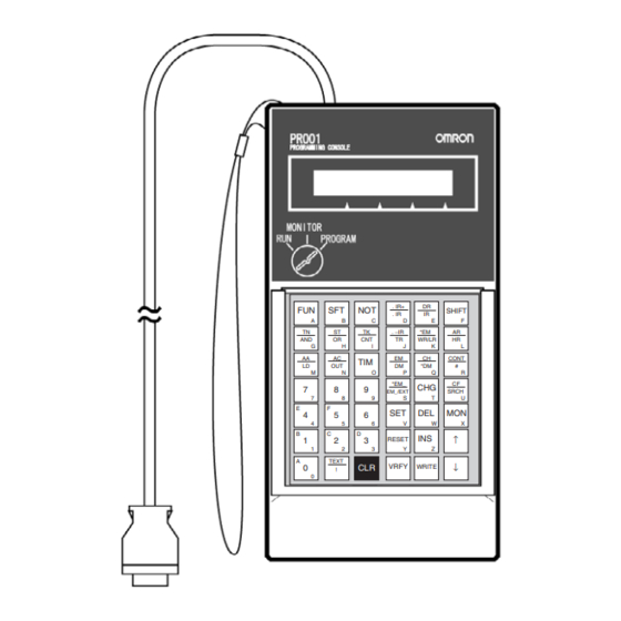
CQM1H-PRO01-E CQM1H-PRO01-E CQM1-PRO01-E C200H-PRO27-E The Programming Console is connected to the peripheral port on the CPU Unit. It cannot be connected to the RS-232C port. In a CS1D Duplex-CPU System, the Programming Console is connected to the active CPU Unit. -
Page 29: Using The Programming Console
Section 1-2 Using the Programming Console Operational Differences The operation of the Programming Console will vary with the CPU Unit that is for CPU Units connected as shown in the following table. These are the only differences in Programming Console operation that vary with the CPU Unit. - Page 30 Verifying data between Reading error information Memory Cards/EM files on current errors and the PLC Note The Programming Console cannot be used to create programs with more than one cyclic task. Use the CX-Programmer if more than one cyclic task is required.
-
Page 31: Programming Console Functions
Instruction Insert See p73. Instruction Delete See p74. Operand Change N.O./N.C. Change See p74. Instruction Variation Change See p75. See p76. Timer/Counter SV change Timer/Counter SV Change 1 (Sets constant or word) Timer/Counter SV Change 2 (Fine adjustment of constant) - Page 32 See p109. N.O./N.C. Change See p110. Instruction Variation Change See p111. Timer/Counter SV Change Timer/counter SV Change 1 (Sets constant or word) Timer/counter SV Change 2 (Fine adjustment of constant) Special Functions See p116. Clock Read/Change See Section 8. PLC Setup See Section 7.
-
Page 33: Unsupported Functions
• Do not pull or twist the cable with excessive force. • The ambient operating temperature is 0 to 55 ° C. Be careful that this tem- perature is not exceeded when the Programming Console is used mounted to a panel. - Page 34 . IR . −IR WR/LR . −IR WR/LR CONT CONT *EM_ EM_/EXT SRCH Keys *EM_ SRCH EM_/EXT Note: Install the CS1W-JS001-E Key Sheet ↑ RESET ↑ RESET TEXT ↓ VRFY WRITE TEXT ↓ VRFY WRITE Cable length: 2 m (The CQM1H-PRO01-E can be connected Connecting Cable directly to the PLC.)
- Page 35 Section 1-5 Functions and Nomenclature Mode Switch The mode switch key can be removed from the switch when the switch is in RUN or MONITOR modes. It cannot be removed when in PROGRAM mode. ✕ MONITOR PROGRAM f: Key can be removed ✕: Key cannot be removed...
- Page 36 Startup Operating Mode The operating mode of the CPU Unit when the power is turned ON depends on the status of address 81 in the PLC Setup (Startup Mode) and the connec- tion status of peripheral devices. Startup Mode setting in...
- Page 37 Functions and Nomenclature Section 1-5 1-5-3 Key Functions Each key has three possible inputs: The normal input, a shift input, and a text input. Refer to page 37. Shift input Shift input Normal input Normal input Normal input Text input...
- Page 38 CONT (Binary or BCD) (Bit address) *EM (indirect *EM_/EM_.EXT *EM_ (Expansion Data Mem- address) EM_/EXT ory including bank number) EXT (memory all clear) CHG Key (Changes to SVs, timer/counter etc.) CF/SRCH Key SRCH (Condition SRCH Flag) SET Key ON dif-...
- Page 39 Up Key Return to the previous Differential ↑ program address Monitor Delete/write Down Key Proceed to the next Differential ↓ program address Monitor Move to the next set- ting Numeric Keys Hexadecimal • • • • • • • • •...
-
Page 40: Programming Console Connection And Installation
Programming Console Connection and Installation Connection The Programming Console can be connected even when power is being sup- plied to the PLC and regardless of whether the CPU Unit is in RUN, MONI- TOR, or PROGRAM mode. 1,2,3... 1. For the C200H-PRO27-E Programming Console, connect the Connecting Cable’s (CS1W-CN224 or CS1W-CN624) connector to the Programming... - Page 41 Check the direction of the connector. Squeeze in on the sides of the connector and then insert it. 3. To disconnect the connector, squeeze the lock release levers on the sides and pull the connector straight out. Lock release lever Panel Mounting Use the C200H-PRO27-E Programming Console when the Programming Console needs to be mounted to a panel.
-
Page 42: Comparison With Previous Models
Start Mode If default startup mode (i.e.,for the PLC to start up in the mode set on the Pro- gramming Console) is set in the PLC Setup and a Programming Console is not connected, a CS1 CPU Unit will start in PROGRAM mode, but a CJ1/CJ1-... -
Page 43: Using The Programming Console
Checking Program Operation ........ -
Page 44: Programming
Pin 3: ON (English messages) (CS1 CPU Units only) Pin 4: OFF (Peripheral port automatic recognition.) Note Be sure to turn OFF pin 1 and pin 4 to enable writing the program via the Programming Console. 4. Connect the Programming Console to the CPU Unit. -
Page 45: Connecting The Programming Console
When using the Programming Console for the first time, perform the following procedure. Note Keystrokes for procedures are illustrated using graphics of the keypad buttons for each step. A list of key names used in the text is provided in Section 1 Installation on page 11. 1,2,3... - Page 46 3. Access the initial display. 000000 CT** • If a memory error is displayed, press the CLR Key several times to re- turn to the initial display. • If an I/O table verification error occurs, I/O VRFY ERR will be dis- played.
- Page 47 • When creating an interrupt task always select INT 1: YES when clear- ing memory. If INT 0: NO is selected, you will not be able to create in- terrupt tasks and it will be necessary to clear memory again using INT 1: YES.
-
Page 48: Inputting Programs
2. Press the Down Key. 000000 CT00 ↓ END(001) When the Down Key is pressed, the END instruction will be generated. When all memory has been cleared, the END instruction will be written to program address 0 of all tasks. - Page 49 Section 2-4 Inputting Programs New programs will be written from the address where the END instruction is displayed. 3. Input the cyclic task program using the following steps. a) Input LD 000000. 000000 000000 Leading zeros do not need to be entered.
- Page 50 4. Read and check the cyclic task program using the following steps. a) Access the initial display. 000000 CT00 … b) Press the Down Key, read the program in order, and confirm that the mnemonics are correct. Correct any errors in the program. 000000 CT00 ↓...
- Page 51 000002 FUN (0??) 000002 FUN (02?) 000002 MOV(021) 000002 MOV ↓ WRITE SV A 0000 Note When writing special instructions be sure to input the function num- ber correctly as a 3-digit number. If the number is abbreviated to “0,”...
-
Page 52: Checking Program Operation
After checking that the program has been written correctly, perform a trial exe- cution of the program. It is not necessary to have I/O Units installed, but when the PLC is switched to MONITOR mode, operation will start, so if I/O Units are connected, either remove the output wires or set the Output OFF Bit to ON. - Page 53 WRITE 4. Monitor the I/O bit status step by step during program execution. Press the Up and Down Keys to read the program and monitor I/O bit sta- tus as shown below. This operation is called monitoring I/O bit status.
- Page 54 ^ OFF 000100 • When there is no I/O Unit at word 0, the status is held ON. When the RESET Key is pressed, the status is set to OFF. • The uppermost bit CIO 000000 is only set to ON, while the SET Key is being pressed.
- Page 55 000100 ^ OFF • When there is no I/O Unit at word 0, the status is held ON. When the RESET Key is pressed, the status is set to OFF. • When the normally closed CIO 000001 is set to OFF, the self-holding status is cleared, and CIO 000100 is set to OFF also.
-
Page 57: Operation
Changing Operating Modes ........ -
Page 58: Starting Operation
Programming Console is connected while the power is ON. 1,2,3... 1. When the power to the PLC is turned ON, the POWER indicator on the CPU Unit will light and the LCD display on the Programming Console will display the following. -
Page 59: Cj1/Cj1-H/Cs1-H Cpu Units
CS1 CPU Units.) 1,2,3... 1. When the power to the PLC is turned ON, the POWER indicator on the CPU Unit will light and the LCD display on the Programming Console will display the following. - Page 60 Section 3-1 Starting Operation 000000 CT** Task No. Note The password input, language selection, and initial displays can be switched for CJ1/CJ1-H/CS1-H CPU Units as shown in the following diagram. CJ1/CJ1-H/CS1-H CPU Units connected. <PRG> 3:ENG~JPN <PRG> 3:JPN~ENG PASSWORD! PASSWORD! <PRG>...
-
Page 61: Changing Operating Modes
“3: ENG → JPN” indicates that English language messages will be dis- played. Press the 3 Key to change the display language. !Caution Before changing the operating mode of the CPU Unit, make sure that doing so will not affect other equipment. -
Page 62: Key Functions
Shift Input Mode The shift input mode is used to enter the text on the top of the key or on the upper-left corner of the key. Shift mode is also used to input hexadecimal A to The key sequence to switch to shift input mode, and the shift input mode dis-... -
Page 63: Clearing Memory Areas
Section 3-4 Clearing Memory Areas • When the text input mode mark is displayed and a key is pressed, the text or numeral on the lower-right corner of the key can be entered. • Pressing the CLR Key to return to the normal key input mode. - Page 64 SHIFT SRCH Note The CIO Area is used for I/O word data: I/O bits, Data Link bits, CS/CJ CPU Bus Unit bits, Inner Board bits, SYSMAC BUS bits, I/O Terminal bits, Special I/ O Unit bits, CompoBus/D (DeviceNet) bits, and work bits. (Inner Board bits, SYSMAC BUS bits, and I/O Terminal bits are supported by CS-series PLCs only.)
-
Page 65: All Clear
(CT00) and no interrupt tasks. Note To create interrupt tasks, always select INT 1: YES when clearing memory. If INT 0: NO is selected, you will not be able to create interrupt tasks unless you clear memory again using INT 1: YES. - Page 66 … 000000CLR MEM CHWA TCDE RESET 2. Specify the areas that are not to be cleared. Refer to page 38 for further details on specifying areas. Example: Specifying the Counter Area not to be cleared. 000000CLR MEM CHWA T DE Counter Area will not be cleared: The "C"...
-
Page 67: Memory Clear
… 000000CLR MEM CHWA TCDE RESET 2. Specify the areas that are not to be cleared. Refer to page 38 for further details on specifying areas. Example: Specifying the Counter Area to not be cleared. 000000CLR MEM CHWA T DE Counter Area will not be cleared: The "C"... -
Page 68: Buzzer Operation
• Press the CLR Key to return to the original display. Buzzer Operation MONITOR PROGRAM This operation is used to turn ON and OFF the buzzer that sounds when Pro- gramming Console keys are pressed. The buzzer ON/OFF operation is per- formed from the mode display. Key Sequence... -
Page 69: Selecting Tasks
MONITOR PROGRAM This operation allows the user to select the task and the type of task (cyclic or interrupt.) From the Programming Console however, only interrupt task num- bers 1,2, and 3 (IT100 to 131) can be newly created. Interrupt task numbers 0 and 4 to 99 (IT132 to 255) cannot be created. - Page 70 Use the CX-Programmer if more than one cyclic task is required. 2. If INT 0: NO is set when memory is cleared, only a cyclic task (CT00) can be created, and interrupt tasks cannot be created. Refer to page 39 for de- tails.
- Page 71 Section 3-6 Selecting Tasks 3. Input the task number. 4. Confirm the task number and then press the WRITE Key to set the task number and return to the initial display. 000000 CT00 WRITE Interrupt Tasks Key Sequence Initial display Task No.
-
Page 72: I/O Table Operations
WRIT ???? Note If the first word for a Rack has been set in advance from the CX-Pro- grammer for a CS1-H or CJ1-H CPU Unit, “Rack 1st Word En” will be displayed to show that the first word has been set. - Page 73 1. Press the FUN, SHIFT, and CH Keys to start the I/O table creation opera- tion. If the first word for a Rack has been set, a message saying so will ap- pear on the second line of the display.
-
Page 74: I/O Table Verify
3-7-2 I/O Table Verify MONITOR PROGRAM This operation is used to compare the I/O table registered in the PLC (regis- tered I/O tables), with the actual I/O Units mounted to the PLC Racks. Key Sequence Initial display SHIFT VRFY... - Page 75 2. Confirm the location of any verification errors. 000000I/O VRFY VRFY RAK1 SLOT10 Slot No. Rack No. 3. Any further errors will be displayed in sequence as the VRFY Key is pressed. 000000I/O VRFY VRFY RM0 RT2 SLOT10 Master Slot No.
- Page 76 Optical I/O No. of Output Words The following display indicates that the number of output words connected to Verification Error a Master mounted to the PLC does not match the number registered in the I/O table. 000000I/O VRFY RM1 No.9 UNITOUT...
- Page 77 CS1 CPU Bus Unit The following display indicates that the type of a CS/CJ CPU Bus Unit (CPU Verification Error Bus Unit) mounted to the PLC does not match the type registered in the I/O table. 000000I/O VRFY CPU BU No.31...
-
Page 79: Writing And Editing Programs
Instruction Change ........ -
Page 80: Inputting Instructions
Procedure for Inputting Instructions MONITOR PROGRAM Programs can be input in PROGRAM mode only. 1,2,3... 1. Press the FUN and CHG Keys to switch tasks and bring up the initial dis- play. Switch tasks 000000 CT00 000000 IT000 Initial display ↓... -
Page 81: Inputting Basic Instructions
000200 000002 2. Press the WRITE Key. 000201 CT00 WRITE END(001) If a mistake is made inputting, press the Up Key to bring up the program address, and re-input the instruction. The data at the address will be over- written. - Page 82 OR NOT OUT NOT AND NOT RSET RESET Designating Bit Addresses Bit type Key sequence Display example CIO bits Bit 15 of CIO 0000 Number 000000 000015 Work bits (WR) Bit 15 of W000 Number WR/LR 000000 W00015 Holding bits (HR)
- Page 83 000000 When clock pulses or Display Condition Flags are designated, the bits listed at Always ON Flag the right can be designated, by using the Up and Down Always OFF Flag Keys. Access Error Flag 0.02s 0.02-s clock pulse 0.1s 0.1-s clock pulse...
- Page 84 SHIFT ,IR10+ (Relative address) Auto-increment (+1) Auto-increment+2 IR10++ ,IR+ ,–IR 000201 SHIFT Number SHIFT ,IR10++ Note The display will toggle between auto-incre- Auto-increment (+2) ment +1 and auto-in- crement +2. Auto-decrement Auto-decrement IR10– ,–IR SHIFT 000201 Number ,-IR10 (Relative address) Auto-decrement (–1)
-
Page 85: Inputting Timer/Counter Instructions: Tim/Cnt
The following example describes how to input TIM 0010 with a SV of 10 s. 1,2,3... 1. Press the TIM Key and input the timer number. 000201 CT00 0010 000201 TIM ↓ #0000 2. Input the set value. In the following example, the set value is #0100 (10 s). 000201 TIM #0100... - Page 86 3. Press the WRITE Key. 000202 CT00 WRITE END(001) If a mistake is made inputting the set value, press the Up Key until the set value is displayed. Then press the CONT/# Key and enter the correct val- Inputting Timer/Counter Instructions Instruction...
- Page 87 E00010 (Word address) Timer PVs T0010 Number 000201 TIM T0100 Counter PVs C0010 Number 000201 TIM C0010 Designating Timer/Counter Set Values (2) Designating Indirect DM/EM Addresses Mode Key sequence Display example Data Registers DR10 (DR) Number SHIFT 000201 TIM DR10...
-
Page 88: Inputting Special Instructions
The following example describes how to input the MOV(021) instruction. 1,2,3... 1. Press the FUN Key, enter the function code, and then press the Down Key. All 3 digits of the function code must be input. In this example, the function code for MOV is 021. - Page 89 Operand Operand WRITE Operation Example The following example describes how to input the <= instruction. 1,2,3... 1. Press the FUN Key and enter the function code. The function code for <= is 318. 000202 FUN (???) 000202 [LD] <=SL(318) 2. Specify the logic type. In this example, OR.
- Page 90 Section 4-1 Inputting Instructions Designating Word (16-bit) Addresses Type Key sequence Display example CIO words CIO0010 Number SHIFT 000000 MOV SV A 0010 Work words (WR) W010 Number WR/LR 000000 MOV SV A W010 Holding words (HR) H010 Number 000000 MOV...
- Page 91 D09999 and E00000 to E09999. Use binary mode to specify D10000 to D32767 and E10000 to E32767. • If 8000 to FFFF Hex are specified as indirect DM addresses in binary mode, E00000 to E32767 in bank 0 of the EM Area will be designated.
- Page 92 SET/RESET Keys. 000202 MOV SV A +4660 Positive RESET 000202 MOV SV A -4660 Negative Note Changes such as those illustrated above cannot be made for BCD data con- stants such as Timer/Counter set values, JMP/Subroutine numbers etc.
-
Page 93: Reading And Searching Programs
Initial display Program address ↑ Operation Example In the following example, address 123456 is read. 1,2,3... 1. From the initial display, specify the address to be read. In this example, pro- gram address 123456 is read. 000000 CT00 … 123456... -
Page 94: Instruction Search
123456 CT00 ↓ 000000 The program address is displayed when using either the Instruction Search or Operand Search operation. 2. Using the Up and Down Keys, read the previous and next program ad- dresses. 123457 CT00 ↓ 002100 123456 CT00 ↑... -
Page 95: Bit Search
3. When the search reaches the END(001) instruction, the following display will appear. 000400 CT00 FIND END(001) SRCH 4. If the SRCH Key is pressed after the search has finished searching to the END(001) instruction, the following display will appear. 000400 CT00 FIND NO END INST END SRCH... - Page 96 3. When the search reaches the END(001) instruction, the following display will appear. 000400 CT00 BIT END(001) SRCH 4. If the SRCH Key is pressed after the search has finished searching to the END(001) instruction, the following display will appear. 000400 CT00 BIT NO END INST END SRCH...
-
Page 97: Editing Programs
This operation is used to overwrite instructions in user programs. Key Sequence Program address display Input mnemonic WRITE Operation Example In the following instruction block, the instruction for address 000200 will be changed to LD NOT 000002. Address Instruction Operand 000200 000001 Changed to LD NOT 000002. -
Page 98: Instruction Insert
Editing Programs Section 4-3 1,2,3... 1. From the initial display, access the address where the instruction is to be changed. 000000 CT00 … 000200 CT00 ↓ 000001 2. Input the instruction and press the WRITE Key. 000201 CT00 WRITE 000200 3. -
Page 99: Instruction Delete
000201 DEL END ↑ 000100 • If the user attempts to delete from an address where there is no in- struction or when END(001) instruction is written, ADR OVER will be displayed. • When multiple-operand instructions are deleted, the set values (oper-... -
Page 100: Bit Address Change
Editing Programs Section 4-3 4-3-4 Bit Address Change MONITOR PROGRAM This operation is used to change bit addresses in operands in the user pro- gram. Key Sequence WRITE Program address display Input operand address Operation Example In the following instruction block, the operand address at 000200, CIO 000001, will be changed to CIO 000002. -
Page 101: Instruction Variation Change
2. Press the NOT Key and then the WRITE Key. 000200 CT00 LD N 000001 000201 CT00 WRITE 000200 3. Use the Up Key to check that LD has been changed to LD NOT. 000200 CT00 ↑ LD N 000001 4-3-6 Instruction Variation Change... -
Page 102: Timer/Counter Sv Changes
000001 4-3-7 Timer/Counter SV Changes MONITOR PROGRAM Timer/Counter SV Change 1: Constant or Word This operation is used to change the set value of a timer/counter in the user program. Key Sequence Designated constant Timer/counter SV display WRITE Designated word Operation Example The following example describes how to change the set value for TIM 0001. - Page 103 #0100 2. Star the set Timer/Counter SV Change 1 operation. 000201SV ? #0100 3. The designated word or constant specified for the set value can be changed from the above display. Changing a Constant Input the constant as follows: 000201SV ?
- Page 104 Section 4-3 Editing Programs 3. Incremented or decremented the constant using the Up and Down Keys. 000201SV U/D? ↑ ↓ #0021 Incremented for the ↓ Down Key. Decremented for the ↑ Up Key. 4. Exit the operation. The new set value will be displayed.
-
Page 105: Checking And Adjusting Programs
Instruction Change ........ -
Page 106: Reading Program Execution Status
1. From the initial display, specify the program address to read. In this exam- ple, program address 123 is specified. 000000 CT00 … 000123 2. Read the program. The ON/OFF status of bits will be displayed as “0” or “1.” 000123 CT00 ↓ 000000... -
Page 107: Simple I/O Monitor
Simple I/O Monitor MONITOR PROGRAM This operation is used to monitor present values in I/O memory one bit or one word at a time. • There are two methods for I/O monitoring, as follows: a) Monitoring specified addresses in I/O memory. - Page 108 Section 5-2 Simple I/O Monitor Operation Example In the following example, auxiliary bit (AR) A40109 is monitored. 1,2,3... 1. From the initial display, input the bit address to be monitored. In this exam- ple, input A40109. 000000 CT00 … CONT...
- Page 109 Simple I/O Monitor present value display (initial status) #0000 to #9999 0000 to 9999 Example: When the present value is 10 s, the values are as follows: Set value input range Simple I/O Monitor present value display (initial status) #0100...
- Page 110 Simple I/O Monitor Operation Example In the following example, TIM 0010 is monitored. 1,2,3... 1. From the initial display, input the number of the timer instruction to be mon- itored. In this example, input TIM 0010. 000000 CT00 … 000000 0010 2.
- Page 111 D00100 FFFF PV (Hexadecimal display) • Press the Up and Down Keys to monitor either the previous or the next word. • Word values can be changed from this display. 3. Press the CLR Key to exit Simple I/O Monitor.
-
Page 112: Monitoring Operands At Specified Program Addresses
Initial display Specify program address One Operand Operation Example In the following example, the PV for the TIM instruction at program address 000200 is monitored. 1,2,3... 1. From the initial display, input the program address of the instruction whose operand is to be monitored. In this example, input program address 000200. -
Page 113: I/O Multipoint Monitor
MONITOR PROGRAM This operation is used to monitor up to four bits or words simultaneously. • Four bits and/or words can be monitored at the same time, but only 2 of these can be displayed simultaneously. Key Sequence Simple I/O Monitor... - Page 114 The present value for D 00000. • A total of up to 4 bits and words can be specified, but only a maximum of 2 of these will be displayed at any one time. If more than 4 bits/words are specified, old ones will be cleared from the monitor operation.
- Page 115 1234 Clearing all Monitor Displays This operation is used to clear from the display all bits/words being monitored in I/O Multipoint Monitor. The specification of the bits/words being monitoring will be saved and the Multipoint I/O Monitor operation can be returned to using the procedure described in the preceding section.
-
Page 116: Monitor Display Format
Monitor Display Format Monitor Display Format The display format for words (16-bit data) in Simple I/O Monitor or I/O Multi- point Monitor can be changed to display formats other then binary (i.e., 4-digit and 2-digit hexadecimal), such as signed decimal, unsigned decimal, and ASCII. -
Page 117: Word (Multipoint) Monitor
• Auxiliary bits • Extended data memory • Index registers • The status of the 16 bits will be shown on the bottom line of the display using 1, 0, S, and R as follows: 1: ON S: Force Set... -
Page 118: Signed Decimal Monitor
Section 5-4 Monitor Display Format 3. Press the CLR Key to stop word monitoring and return to the Simple I/O Monitor display. 2670 F000 5-4-2 Signed Decimal Monitor MONITOR PROGRAM This operation converts the hexadecimal contents of words from 2’s comple- ment to a signed decimal data display. -
Page 119: Unsigned Decimal Monitor
Section 5-4 Monitor Display Format 5. Press the CLR Key again to return the display from Signed Decimal Mon- itor to either Simple I/O Monitor or I/O Multipoint Monitor. 2670 FFF0 5-4-3 Unsigned Decimal Monitor MONITOR PROGRAM This operation converts the hexadecimal contents of word data into unsigned decimal data for display. -
Page 120: Ascii Monitor
D 00000 D00000 4142 2. Convert the display format to ASCII display. D00000 "AB" ,–IR ,–IR ,–IR 3. Press the CLR Key to exit ASCII display and return to either Simple I/O Monitor or I/O Multipoint Monitor. D00000 4142... -
Page 121: Changing Word (16-Bit) Present Values
GRAM mode. The CPU Unit will refresh I/O even in PROGRAM mode. If the status of a bit allocated to an Output Unit, Special I/O Unit, or CPU Bus Unit is changed, the load connected to the Unit may operate unexpectedly. -
Page 122: Changing Pvs From Hexadecimal Or Bcd Display
GRAM mode. The CPU Unit will refresh I/O even in PROGRAM mode. If the status of a bit allocated to an Output Unit, Special I/O Unit, or CPU Bus Unit is changed, the load connected to the Unit may operate unexpectedly. - Page 123 GRAM mode. The CPU Unit will refresh I/O even in PROGRAM mode. If the status of a bit allocated to an Output Unit, Special I/O Unit, or CPU Bus Unit is changed, the load connected to the Unit may operate unexpectedly.
-
Page 124: Changing Pvs From Unsigned Decimal Monitor
GRAM mode. The CPU Unit will refresh I/O even in PROGRAM mode. If the status of a bit allocated to an Output Unit, Special I/O Unit, or CPU Bus Unit is changed, the load connected to the Unit may operate unexpectedly. -
Page 125: Changing Pvs From The Ascii Monitor
GRAM mode. The CPU Unit will refresh I/O even in PROGRAM mode. If the status of a bit allocated to an Output Unit, Special I/O Unit, or CPU Bus Unit is changed, the load connected to the Unit may operate unexpectedly. -
Page 126: Changing Pvs From The Word (Multiple-Bit) Monitor
GRAM mode. The CPU Unit will refresh I/O even in PROGRAM mode. If the status of a bit allocated to an Output Unit, Special I/O Unit, or CPU Bus Unit is changed, the load connected to the Unit may operate unexpectedly. -
Page 127: Forcing Bits On/Off
PROGRAM mode. The CPU Unit will refresh I/O even in PROGRAM mode. If the status of a bit allocated to an Output Unit, Special I/O Unit, or CPU Bus Unit is changed, the load connected to the Unit may operate unexpectedly. -
Page 128: Temporary Force Set/Reset
From the I/O Multipoint Monitor, the bit at the top of the display will be changed. 2. When a bit has been Force Set, an “S” will appear and when it has been Force Reset, an “R” will appear on the display. The forced ON/OFF status of the bit will not be affected by external input changes or the result of ex- ecuting a command. -
Page 129: Differential Monitor
^ OFF 000001 ^ ON From the I/O Multipoint Monitor, the bit at the top of the display will be changed. 2. The bit will be force-set/reset only while the key is being pressed. While the key is being pressed, a black square will be displayed. -
Page 130: Online Editing
Bit 10 of CIO 0100 010010 ^ OFF From the I/O Multipoint Monitor, the bit at the top of the display will be mon- itored. 2. Set detection of the differentiate up status. In this example, an OFF to ON change is detected in the status of CIO 010010. -
Page 131: Instruction Add
MONITOR PROGRAM See note. This operation is used when the CPU Unit is in MONITOR mode to add an instruction to the end of the user program. Note Refer to 4-1 Inputting Instructions for details on adding instructions in PRO- GRAM mode. -
Page 132: Instruction Insert
3. Press the WRITE Key once more. 123457 CT00 WRITE END(001) 4. Continue to specify the next instruction to be added and press the WRITE Key after each one. ONLINE EDIT? WRITE 000100 5. Press the WRITE Key once more. -
Page 133: Instruction Delete
Operand 000200 000001 AND 000100 will be inserted. 000201 000200 1,2,3... 1. From the initial display, access the program where the address to be in- serted. 000000 CT00 … 000201 CT00 ↓ 000200 2. Specify the instruction to be inserted, and press the INS Key. -
Page 134: Bit Address Change
PROGRAM See note. This operation is used when the CPU Unit is in MONITOR mode to change bit addresses used as operands in the user program. Note Refer to 4-3-4 Bit Address Change for details on changing bit addresses in PROGRAM mode. -
Page 135: N.o./N.c. Change
WRITE 000200 After pressing the WRITE Key the second time, the altered program will be executed from the next scan. 4. Press the Up Key to check that the address of the bit operand has been changed. 000200 CT00 ↑... -
Page 136: Instruction Variation Change
WRITE 000200 After pressing the WRITE Key the second time, the altered program will be executed from the next scan. 4. Use the Up Key to check that LD has been changed to LD NOT. 000200 CT00 ↑ LD N... -
Page 137: Timer/Counter Sv Change
Note Refer to 4-3-7 Timer/Counter SV Changes for details on changing timer/ counter set values in PROGRAM mode. Timer/Counter SV Change 1: Constant or Word This operation is used to change the set value of a timer/counter in the user program. Key Sequence... - Page 138 WRITE 000100 Timer/Counter SV Change 2: Fine Adjustment of Constant This operation is used to increment or decrement the set value of a timer/ counter with a constant specified for the set value in the user program. Key Sequence ↓...
- Page 139 Section 5-8 Online Editing 3. Incremented or decremented the constant using the Up and Down Keys. 000201SV U/D? ↑ ↓ #0021 Incremented for the ↓ Down Key. Decremented for the ↑ Up Key. 4. Exit the operation. The new set value will be displayed.
-
Page 141: Maintenance Operations
Cycle Time Read..........Reading/Clearing Error Messages ....... . . -
Page 142: Clock Read/Change
MONITOR PROGRAM See note Note When the CPU Unit is in RUN mode, the clock can be read but can- not be changed. This operation is used to read or set the CPU Unit’s internal clock. • A battery is not installed in CS1-series PLCs when they are shipped. -
Page 143: Cycle Time Read
5. Press the CLR Key to exit. Cycle Time Read MONITOR PROGRAM This operation is used to display the average cycle time for all programs (the total of all tasks) that are being executed. Key Sequence Initial display Operation Example 1,2,3... -
Page 144: Reading/Clearing Error Messages
1. Fatal operating errors can only be displayed and reset in PROGRAM mode. 2. If the source of the error is not removed, the error will not be reset and the error message will continue to be displayed. 3. When errors are read using the Down Key, the error will not be reset and current errors can be confirmed. - Page 145 CPU WAIT'G When several errors have occurred at the same time, the error messages will be displayed in order from 1 to 21, as listed below. (In order from the most serious to least serious.) Fatal Operating Errors 1,2,3...
- Page 146 13. PLC Setup Error PC SETUP ERR 14. I/O Verification Error I/O VRFY ERR 15. Non-fatal Inner Board Error NO-FTL INNER ERR 16. CS1 CPU Bus Unit Error Unit No. CPU BU ERR 17. Special I/O Unit Error Unit No. SIOU ERR...
- Page 147 SIOU SETUP MSG(046) Messages The MSG(046) instruction can be used to record up to 8 messages for display on the Programming Console. These messages will be displayed when the MON Key is pressed after all other error messages have been displayed. If more than one MSG(046) instruction has been executed, the following meth- ods can be used to display the other MSG(046) messages.
- Page 148 MSG(046) Instruction The MSG(195) instruction reads sixteen words of extended ASCII contained in 16 words from M to M+15 and displays the message on a Peripheral Device (e.g., the Programming Console). The displayed message can be up to 32 characters long, i.e., each ASCII character code requires eight bits (two dig- its).
-
Page 149: Memory Card Operations
File Memory Operations ........ -
Page 150: File Memory Operations
Note I/O name table files (extension .SBL) and block comment files (extension .RGL), cannot be handled from the Programming Console. For details on how to specify the starting bank for EM area file memory, refer to Section Section 8 PLC Setup Procedure. -
Page 151: Memory Card Format
With CS1-series PLCs, Memory Cards and the specified range of EM File Memory can be used as file memory. Regardless of whether it’s the UM Area, I/O memory or the Parameter Areas (e.g., PLC Setup), all data is saved as files. -
Page 152: File Write
It cannot be changed. File Write MONITOR PROGRAM This operation transfers the UM Area, specified I/O memory area range, or PLC Setup data from the CPU Unit to a Memory Card or EM File Memory. Key Sequence ↓ CONT Initial display... - Page 153 Section 7-3 Operation Example In the following example, CIO 2345 to CIO 2446 in the CIO Area of the CPU Unit are transferred to a Memory Card as the file “SAMPLE.IOM.” Note For creation (and transfer to a Memory Card) of an AUTOEXEC file (a file that automatically transfers data when the power is turned ON), refer to page 130.
- Page 154 Always select DM< when creating a data file that is automatically transferred when the power is turned ON (AUTOEXEC.IOM). c) If EM0_ is displayed, input the number of the EM bank from 0 to C. d) The Parameter Areas include the PLC Setup, registered I/O ta- bles, routing tables, and CPU Bus Unit Setup.
- Page 155 .STD • Press the Up and Down Keys to move the cursor. • Change the “0” in the file name to “1” to transfer the file to EM File Memory instead of to the Memory Card. • Press the CF/SRCH Key to display the file names already on the Mem- ory Card or EM File Memory.
-
Page 156: File Read
Operation: Select “DM<” as the transfer type and “20000” as the transfer start address. When the power is turned ON, AUTOEXEC.IOM files will be read from the Memory Card and all data from the start of the file will be transferred to the Data Memory area, starting at D20000. AUTOEXEC.IOM... - Page 157 CIO< CF_CARD~PC? CIO WRITE 0000ED 6143 Transfer start Transfer end address address 5. Use the Up and Down Keys to select the type of data to be transferred. UM Area CF_CARD~PC?(OBJ) XFER TYPE UM< CIO Area CF_CARD~PC?(IOM) ↑ ↓ XFER TYPE CIO<...
- Page 158 Transfer destination end address CF_CARD~PC?(IOM) WRITE FILE"0:~ " 0: Memory Card 1: EM File Memory 7. Switch to text input mode to enter the name of the file to transfer to the CPU Unit. (See note.) CF_CARD~PC?(IOM! TEXT SHIFT FILE"0:~ "...
- Page 159 LD M • Press the Up and Down Keys to move the cursor. • Change the “0” in the file name to “1” to transfer the file from EM File Memory instead of the Memory Card. Note Press the CF/SRCH Key to display the file names on the Memory Card or EM File Memory.
-
Page 160: File Verify
Verify end address WRITE VRFY Operation Example In the following example, CIO 2345 to CIO 2446 in the CPU Unit are verified against the Memory Card file “SAMPLE.IOM.” 1,2,3... 1. From the initial display, access the Memory Card operations menu. - Page 161 VRFY TYPE CIO< VRFY? WRITE 0000ED 6143 Verify start Verify end address address 4. Use the Up and Down Keys to select the type of data to be verified. UM Area VRFY? (OBJ) VRFY TYPE UM< CIO Area VRFY? (IOM) ↑...
- Page 162 DM P • Press the Up and Down Keys to move the cursor. • Change the “0” in the file name to “1” to verify the file to a file in EM File Memory instead of the Memory Card. Note Press the CF/SRCH Key to display the file names on the Memory Card or EM File Memory.
-
Page 163: File Delete
DELETE TYPE CIO< (IOM) WRITE FILE"0:~ " 0: Memory Card 1: EM File Memory 4. Use the Up and Down Keys to select the type of data to be deleted. UM Area (OBJ) DELETE TYPE UM< CIO Area (IOM) ↑... - Page 164 DM P • Press the Up and Down Keys to move the cursor. • Change the “0” in the file name to “1” to delete a file from EM File Mem- ory instead of the Memory Card. Note Press the CF/SRCH Key to display the file names on the Memory Card or EM File Memory.
- Page 165 Section 7-6 File Delete 8. Confirm the file to be deleted. DEL OK? (IOM) WRITE FILE"0:SAMPLE " 9. Execute the deletion by pressing the WRITE Key. DEL END (IOM) WRITE FILE"0:SAMPLE "...
-
Page 167: Plc Setup Procedure
PLC Setup Procedure ........ -
Page 168: Plc Setup Procedure
Note When in RUN or MONITOR mode, contents of settings can be read, but set- ting cannot be performed. This operation is used to read and write data from and to the PLC Setup Area in the CPU Unit. Key Sequence... - Page 169 PC SETUP ↓ +209 0000 Set value When the set value is displayed, pressing the Up or Down Keys will display the previous or next address. 3. Use the following procedure to change the set word. PC SETUP +209 0000...
- Page 170 PLC Setup Procedure Section 8-1 Example: Changing the value to 2,000 ms. PC SETUP SHIFT +209 0000 80C8 PC SETUP WRITE +209 80C8 4. Press the CLR Key to return to the PLC Setup display.
-
Page 171: Ascii Coding Sheet
Appendix A ASCII Coding Sheet The following list shows the range of characters that can be displayed on the Programming Console. Symbols and Japanese “katakana” characters however, cannot be input from the Programming Console. Right- Leftmost bit most 0, 1, 8, 9 ”... -
Page 173: Error Messages
Appendix B Error Messages Error messages will be displayed on the Programming Console, whenever an operating error is made. Refer to the following table for operating errors and their remedies. Error message Remedy CHK MEM (ROM) Pin 1 on the CPU Unit’s DIP switch is set to ON (write protect). Reset this pin to OFF (write enabled). -
Page 175: Plc Setup Coding Sheets For Programming Console
Appendix C PLC Setup Coding Sheets for Programming Console Use the following coding sheets when setting the PLC Setup from a Programming Console. Address 10 @@@@ Value (Hex) Rack 0, Slot 0 I/O response time 8 ms No filter 0.5 ms... - Page 176 PRCN Mode on Programming Console's mode switch PROGRAM mode MONITOR mode RUN mode Note PRCN, PRG, MON, and RUN can be selected using the Up and Down Keys. Address 83 @@@@ (CS1D CPU Units for Single-CPU Systems and CS1-H/CJ1-H CPU Units only)
- Page 177 Note: @@ is the division size (words). Note The above settings assume that both bit 11 (Inner Board parameter area) and bit 10 (Inner Board variable area) are set to 0. Address (CS1D CPU Units only) 121@@@@...
- Page 178 Do not detect. Detect. 4000 Detect. Do not detect. 0000 Detect. Detect. Note Interrupt task error detection cannot be set for CS1D Duplex-CPU Systems. Address (CS1-H/CJ1-H/CS1D CPU Units only) 129 @@@@ Value (Hex) Error History Storage of FAL 8000 Do not store FAL in error history.
- Page 179 0007 0008 38,400 bps 0009 57,600 bps 000A 115,200 bps Note For NT Links: 0000 to 0009 Hex = Normal NT Link, 000A = High-speed NT Link. Address 147@@@@ Peripheral port Value (Hex) Host link Unit No. 0000 No. 0 0001 No.
- Page 180 19,200 bps 0008 38,400 bps 0009 57,600 bps 000A 115,200 bps Note For NT Links: 0000 to 0009 Hex = Normal NT Link, 000A = High-speed NT Link. Address 162@@@@ RS-232C port Value (Hex) No-protocol mode delay 0 ms 0000...
- Page 181 Value (Hex) No-protocol Mode reception data volume No-protocol Mode end code setting Value (Hex) None (Specify the amount of data being received) Yes (Specify the end code) End code is set to CR+LF No-protocol Mode start code setting Value (Hex)
- Page 182 0 to 7 Value (Hex) Background processes Text string Data shifting Table data instructions instructions instructions Note These settings are not supported for CS1D Duplex-CPU Systems. Address 208@@@@ Minimum cycle time Value (Hex) 0000 Cycle time not fixed 0001 Cycle time fixed: 1 ms...
- Page 183 Special Peripheral Servicing Unit Numbers Value (Hex) Setting No special servicing 10 to 1F CPU Bus Units 0 to 15 (unit number + 10 Hex) 20 to 7F Special I/O Units 0 to 95 (unit number + 20 Hex) Inner Board RS-232C port...
- Page 184 Special Peripheral Servicing Unit Numbers Value (Hex) Setting No special servicing 10 to 1F CPU Bus Units 0 to 15 (unit number + 10 Hex) 20 to 7F Special I/O Units 0 to 95 (unit number + 20 Hex) Inner Board RS-232C port...
- Page 185 Node address of node excluded from write protection All nodes in specified network Value (Hex) FINS command source network address Network address of node excluded from write protection. Note These settings are supported only for CS-series CPU Unit Ver. 2.0 or later.
-
Page 187: Index
A–B N.O./N.C. change online All Clear Timer/Counter SV changes ASCII coding sheet error messages fatal operating errors AUTOEXEC non fatal operating errors precautions reading/clearing bit address change errors bit addresses verification errors for inputting basic instructions bit search using bit addresses... - Page 188 I/O multipoint monitor instruction variations I/O multipoint monitor results interrupt tasks operands at specified program addresses signed decimal monitor Japanese messages simple I/O monitor change to English specified bits Timer/Counter completion flags K–L...
- Page 189 ASCII monitor changing from the word monitor changing from unsigned decimal monitor selecting tasks simple I/O monitor...
-
Page 191: Revision History
Revision History A manual revision code appears as a suffix to the catalog number on the front cover of the manual. Cat. No. W341-E-05 Revision code The following table outlines the changes made to the manual during each revision. Page numbers refer to the previous version. - Page 193 Regional Headquarters OMRON EUROPE B.V. Wegalaan 67-69, NL-2132 JD Hoofddorp The Netherlands Tel: (31)2356-81-300/Fax: (31)2356-81-388 OMRON ELECTRONICS LLC 1 East Commerce Drive, Schaumburg, IL 60173 U.S.A. Tel: (1)847-843-7900/Fax: (1)847-843-8568 OMRON ASIA PACIFIC PTE. LTD. 83 Clemenceau Avenue, #11-01, UE Square,...
- Page 194 Authorized Distributor: Cat. No. W341-E1-05 Note: Specifications subject to change without notice Printed in Japan This manual is printed on 100% recycled paper.