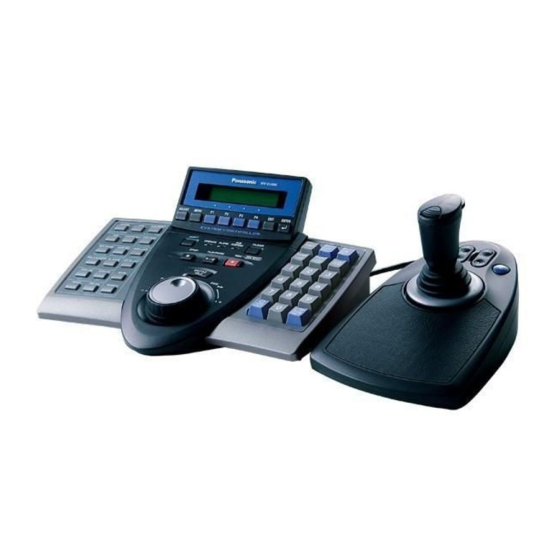
Panasonic WV-CU650 Operating Instructions Manual
System controller
Hide thumbs
Also See for WV-CU650:
- Operating instructions manual (126 pages) ,
- Product catalog (125 pages) ,
- Addendum (48 pages)

Related Manuals for Panasonic WV-CU650


Summary of Contents for Panasonic WV-CU650
-
Page 1: System Controller
System Controller Operating Instructions WV-CU950 Model Nos. WV-CU650 Before attempting to connect or operate this product, please read these instructions carefully and save this manual for future use. - Page 2 ENGLISH VERSION Caution: Refer to the name plate on the rear of this product to verify identifications and power ratings. CAUTION RISK OF ELECTRIC SHOCK DO NOT OPEN CAUTION: TO REDUCE THE RISK OF ELECTRIC SHOCK, DO NOT REMOVE COVER (OR BACK). NO USER-SERVICEABLE PARTS INSIDE.
-
Page 3: Important Safety Instructions
IMPORTANT SAFETY INSTRUCTIONS 1) Read these instructions. 2) Keep these instructions. 3) Heed all warnings. 4) Follow all instructions. 5) Do not use this apparatus near water. 6) Clean only with dry cloth. 7) Do not block any ventilation openings. Install in accordance with the manufacturer's instructions. 8) Do not use near any heat sources such as radiators, heat registers, stoves, or other apparatus (including amplifiers) that produce heat. -
Page 4: Limitation Of Liability
AL CO., LTD. BE LIABLE TO ANY PARTY OR ANY PER- SON, EXCEPT FOR CERTAIN WARRANTY PROGRAM OFFERED BY THE LOCAL DEALER OF PANASONIC, FOR THE CASES INCLUDING BUT NOT LIMITED TO BELOW: (1) ANY DAMAGE AND LOSS, INCLUDING WITHOUT LIM-... -
Page 5: Table Of Contents
I Wiper Control ...52 I Defroster Control ...53 I Auxiliary Control ...53 I Other Functions ...53 ALARM CONTROL ...54 I System Controller Behavior during the Alarm Mode ...54 I Alarm Reset ...54 I Alarm Suspension ...54 I Alarm History Search ...54 MENU FUNCTION DESCRIPTIONS ...57... -
Page 6: Preface
PREFACE System Controller WV-CU950 and WV-CU650 are designed for setup and operation of cameras and other system units installed in a surveillance system. FEATURES • This product can control cameras, matrix switchers, and recording devices such as digital disk recorders. -
Page 7: Precautions
PRECAUTIONS • Refer all work related to the installation of this appliance to qualified service personnel or system installers. • Do not block the ventilation opening or slots on the cover. To prevent the appliance from overheating, place it at least 5 cm {2 inches} away from the wall. -
Page 8: Document Convention
This document describes only operating procedures performed in the PS·Data mode. When you use System Controller WV- CU950 or WV-CU650 in modes other than PS·Data, the operating procedures differ depending on system connections. Refer to the operating instructions of system devices for details. -
Page 9: Detailed Product Description
DETAILED PRODUCT DESCRIPTION... -
Page 10: Major Operating Controls And Their Functions
Note: Available functions differ depending on connected devices. q Operation indicator (OPERATE) This indicator is lighting while power is supplied to the system controller. w Alarm indicator (ALARM) This indicator blinks when an alarm is activated. Blinking changes to steady light when the alarm is auto- matically reset. - Page 11 • When you press after entering numeric buttons, this button selects an alarm input. Note: This function is available only when the system controller is connected to System 850 Matrix Switcher. o Camera function/System function button (CAM FUNC/SYS FUNC) • Recalls a function of camera by the function number. •...
- Page 12 Note: This operation differs from “Hold playback speed” performed by holding the shuttle ring of recorder. When you hold the playback speed from the system controller, the EL-ZOOM, MULTI- SCREEN, and OSD buttons are unavailable. • If you press this button again, normal playback speed is recovered.
-
Page 13: Rear View
• These ports are used for connection with the system controller and other system units via RS-485 communi- cation. • These ports used when adding other system controller connections. $8 Mode Selection switches (MODE) The operation mode of system controller is selected with these switches. -
Page 14: I 3D Joystick Unit
I 3D Joystick Unit This joystick unit is used to operate combination cameras and pan/tilt heads manually. %2 Top button The top button is pressed to recall a function already assigned. %3 Zoom wheel controller This controller is used for zooming cameras equipped with specific lenses. -
Page 15: I Lcd Display Descriptions
I LCD Display Descriptions The following are examples of LCD display after login in the PS·Data mode. Notes: • Some parts of LCD displays, described on this document, may differ from the actual status. • Refer to the operating instructions of connected devices for details on LCD display in modes other than PS·Data. G Default Status (LCD Display After Login) q Monitor number The number of selected monitor is displayed. - Page 16 G Main Menu (Menu Functions) q Category The category of selected menu function is displayed. w Function number The function number of selected menu function is dis- played. Note: Refer to p. 58 Menu Function Categories. G Sub Menu (Menu Functions) q Function name The name of selected menu function is displayed.
- Page 17 HD316 Controller No.1 No Exist Error HD316 This message is displayed when no system controller is set to CONTROLLER NO.1. Check that a system controller is set to CONTROLLER NO. 1 (Refer to p. 25 CONTROLLER NO. Switch Setting.)
-
Page 19: Installations And System Connections
INSTALLATIONS AND SYSTEM CONNECTIONS... -
Page 20: Installations And Connections
PS·Data, refer to the operating instructions of connected devices. Camera 1 Monitor 1 Monitor 2 Digital Disk Recorder WJ-HD300 Series Unit Address (System) : Used when adding other WV-CU950/650 system controllers (Available up to 3) System Controller WV-CU950/650 (Main unit) ATTENTION 10/100 BASE-T Camera 8 Camera 9 to Camera 12 •... -
Page 21: I Connection With The 3D Joystick Unit
I Connection with the 3D Joystick Unit Connect the main unit and 3D joystick unit as follows. Main unit CAUTION ATTENTION SERIAL DATA 10/100 BASE-T JOYSTICK Combination code label has been stuck on the bottom. Cable (supplied) Note: Use the main unit and 3D joystick unit whose combination codes are identical. I Adjustment of 3D Joystick To adjust the altitude of 3D joystick, turn the adjusting screw to the right or left. -
Page 23: Wv-Cu950/650 Setup Procedures
WV-CU950/650 SETUP PROCEDURES... -
Page 24: Setup Procedures (Hardware)
You will perform this setting when using two or more system controllers in daisy chain connections. (Refer to p. 25 CONTROLLER NO. Switch Setting.) 3. Perform WV-CU650 setups after entering the adminis- trator password. You will perform the settings concerning password and communication between system controllers and other system units, etc. -
Page 25: I Controller No. Switch Setting
You will determine controller-number settings by moving the CONTROLLER NO. switch at the rear panel. G Setting for PS·Data/Terminal Mode If using only one system controller Maintain the switch setting as “1 (factory default position)”. If using two or more system controllers in daisy chain connections Up to 4 system controllers are connectable in the system. -
Page 26: Setup Procedures (Firmware)
To change the setting, refer to p. 31. • Take a note of your administrator password. I Setting Modes If you power on the system controller while pressing the fol- lowing buttons, the system will run in an associated setting mode. -
Page 27: I Ps·data Communication Setting
6. Turn off the power. I PS·Data Communication Setting This setting is required to establish a connection between the system units and system controller. List of PS·Data communication settings Setting Item Available setting parameter(s) Baud Rate 4800 / 9600 / 19200 bps... -
Page 28: Baud Rate Setting
5. Select an item you wish to set up by rotating the JogDial. Baud rate PS Data Com. Setup • Baud Rate The speed of communication between the system controller and other system units Parity bit PS Data Com. Setup • Parity Bit None The parity bit, added to the data, to perform parity check (Refer to p. - Page 29 G Parity Bit Setting 1. Select “Parity Bit” by rotating the JogDial. (Refer to Step 5 in p. 28 Operation.) 2. Press the CAM (SET) button. The LCD display will change from the display mode to the editing mode. PS Data Com. Setup PS Data Com.
- Page 30 G Group Address Setting for System Controller Note: Remain the factory default. When you have mistaken- ly changed the setting, recover the factory default as follows. 1. Select “Cnt G-Adr.” by rotating the JogDial. (Refer to Step 5 in p. 28 Operation.) 2.
-
Page 31: I To Change The Administrator Password
I To Change the Administrator Password You can change the administrator password. The factory default is “650”. G Operation 1. Turn off the power. 2. Turn on the power while holding down the button 1 and MON (ESC) button. “Admin Password” entry form will appear to perform the setting. -
Page 32: I Ps·data Database Copy
6. Turn on the power of destination system controller. Login is not required. 7. Turn on the power of source system controller while holding down the button 2 and MON (ESC) buttons. “Admin Password” will appear on the LCD to enter the password. -
Page 33: I Ps·data Operator Password Check
G Operation 1. Turn off the power. 2. Turn on the power of system controller while holding down the button 4 and MON (ESC) button. “Admin Password” will appear on the LCD to enter the password. -
Page 35: Operating Procedures (Ps·data)
OPERATING PROCEDURES (PS·DATA) -
Page 36: Before Operation
Login standby display appears. I Power-off system composition. After operation, power off the system controller as follows. 1. Log out from the system. (Refer to p. 40.) 2. Unplug the AC adapter from the AC outlet. When leaving away from the system controller... -
Page 37: I Basic Operation Flow
I Basic Operation Flow Login System Unit Selection Monitor Selection System Unit Setup and Operation Logout Camera Selection Camera setup and control Login Unit selection Monitor selection Operation (Multiscreen segment switching and sequence Camera selection Operation (Panning, Tilting, and zooming, etc.) Logout at the end of operation... -
Page 38: I Lcd/Buzzer Adjustment
I LCD/Buzzer Adjustment You can perform the settings of LCD brightness, LCD con- trast, alarm buzzer, or button buzzer as follows. 1. Press the ADJUST button to select a desired menu. Every pressing the button will display the brightness setting menu → contrast setting menu → alarm buzzer setting menu →... - Page 39 • When the ID or password is wrong, “Invalid” blinks on the LCD. Then, the LCD returns to the login standby display. _____ • When a system controller cannot communicate properly with a system unit, the LCD display after login becomes as follows. __∗ ∗ ∗...
-
Page 40: I If You Have Forgotten The Login Password
I If You Have Forgotten the Login Password Refer to the system administrator. I Operation Start (Auto Login) When auto login is set to ON, operators can log into the system without entering their passwords. The LCD display after power-on becomes as follows. (Refer to p. 71 Auto Login/Logout Setup for details on the setting.) 1. -
Page 41: Unit Selection
UNIT SELECTION To control the system, you need to select a desired unit (system unit, recorder, monitor, or camera) at the begin- ning. I System Unit Selection Notes: • In advance, you need to set the unit number for each system unit. -
Page 42: I Monitor Selection
I Monitor Selection When two or more monitors are connected to a system unit, you can select a desired monitor. When monitor selection is unavailable, “Mon- -“ appears on the LCD. The selected system unit does not support moni- tor selection. 1. -
Page 43: System Unit Control
SYSTEM UNIT CONTROL The following are the procedures to control system units (including recorders). I Multiscreen Display The following procedure is available when a selected sys- tem unit (for example, a hard disk recorder) has the multi- screen display function. 1. -
Page 44: I On-Screen Display (Osd) Control
I On-screen Display (OSD) Control You can toggle the OSD information (display parameters such as camera title, monitor number, and recorder num- ber) on the active monitor screen. 1. Select a desired monitor. (Refer to p. 42 Monitor Selection.) 2. To toggle the OSD information, press the OSD button. Note: OSD information differs depending on system units. -
Page 45: Recorder Control
RECORDER CONTROL From this system controller, you can control the following functions of digital disk recorders supporting PS·Data. You will control a recorder in the status in which a recorder has been selected. Note: Some parts of monitor displays, described on this document, may differ from the actual status. - Page 46 Controls commonly available <Main unit> Shuttle ring clockwise: Moves to the next page. Shuttle ring counterclockwise: Moves to the previous page. JogDial clockwise or counterclockwise: Changes the selected parameter. Numeric buttons: Enters numeric parameters. CAM (SET) button: Determines the selected parameter or searching filter setting.
-
Page 47: Lcd Display
Example of searching filter display and settings 1. Repeat pressing the SEARCH/T&D SEARCH button to display the recording event list window. TIME&DATE CAMERA REC EVENT TEXT TIME&DATE REC EVT APR.25.03*12:34:56 AM 01ch MANUAL ABCDEFGHIJKLMNOP APR.25.03*12:34:56 AM 01ch MANUAL ABCDEFGHIJKLMNOP APR.25.03*12:34:56 AM 01ch MANUAL ABCDEFGHIJKLMNOP... - Page 48 Example of F1 button use 1. Press the SEARCH/T&D SEARCH button. Record List will be displayed on the active monitor. DATE MAY29.00 GROUP TIME 010009 23:59:59 010008 22:15:40 010007 21:00:07 17:33:05 010006 010005 7:23:11 010004 6:59:44 010003 8:55:28 010002 0:01:28 (TOTAL COPY DONE! LEFT:20%...
-
Page 49: I Time & Date Search Playback
I Time & Date Search Playback You can search playback images by entering a desired recording date and time. Note: To cancel the entry, press the MON (ESC) or EXIT button. The LCD display will return to the normal status. 1. -
Page 50: Camera Control
CAMERA CONTROL You can control cameras from this system controller. I Camera Panning/Tilting Control The following procedure is available when panning/tilting heads or combination cameras are connected to system units. 1. Select a system unit, monitor, and desired camera. (Refer to p. 41 System Unit Selection, p. 42 Monitor Selection, and p. -
Page 51: I Preset Position Control
I Preset Position Control Preset position is the function to register camera monitoring positions (preset positions) associated with position num- bers. By entering the position numbers, you can move cam- eras to the preset positions. Note: To activate this function, you need to register the pre- set positions of combination camera. -
Page 52: I Camera Position Control
I Camera Selection Recall Every time you select a camera or camera position, this system controller memorizes up to 10 steps of camera selection. You can recall these operations in order or reverse order. In the following procedure, you can track back the camera images formerly displayed. -
Page 53: I Defroster Control
I Defroster Control The following procedure is available when a selected cam- era (housing) is equipped with a defroster. 1. Select a system unit, monitor, and desired camera. (Refer to p. 41 System Unit Selection, p. 42 Monitor Selection, and p. 42 Camera Selection.) 2. -
Page 54: Alarm Control
Alarm Mode When an alarm signal is input to cameras or system units, this system controller is notified that an alarm has been activated. Then, the ALARM indicator will blink. During the alarm mode, “Alarm” sign will blink on the LCD, and the camera number is displayed as “- - -“. -
Page 55: Edit Group
<Joystick unit> 3D joystick upward (L): Moves the cursor up. 3D joystick downward (M): Moves the cursor down. 3D joystick to the left (t): Moves the cursor to the left. 3D joystick to the right (s): Moves the cursor to the right. - Page 56 G Operation (WJ-HD200 Series) Alarm Recall Edit Note: WJ-HD200 Ver. 1.24 later or WJ-HD220 supports alarm history search. (Refer to the operating instruc- tions of recorder.) Available buttons and functions F1 button: Edit You will press this button when editing the Search Editing Area on the ALARM RECALL window.
-
Page 57: Menu Function Descriptions
MENU FUNCTION DESCRIPTIONS You can assign frequently-used menu functions (system functions and camera functions, etc.) to the F1 to F8 button of system controller. (=Button function) In addition, you can also assign the menu functions to the A, B and top buttons of 3D joystick unit. -
Page 58: I Menu Function Categories
I Menu Function Categories Menu functions are classified in the following categories. Select a desired function for assignment or operation. G Camera Functions (CAM) Camera Setup LCD MENU Camera Setup • This function displays or closes the camera setup menu for system settings. - Page 59 G System Functions (SYS) System Setup LCD MENU SYS 301 System Setup You will open the setup menu of system unit and change the settings. Switcher OSD (WJ-SX150 Series only) LCD MENU SYS 302 Switcher OSD Displays or hides the OSD items displayed on monitors connected to the matrix switcher.
- Page 60 Cam-Unit Map LCD MENU Cam-Unit Map You will register cam-unit maps (the association of camera numbers and unit numbers). HDD-Unit Map LCD MENU HDD-Unit Map You will register HDD-unit maps (the association of recorder numbers and unit numbers). LCD Title LCD MENU LCD Title You will edit the function names of F1 to F8, which are dis-...
-
Page 61: I To Recall Menu Functions
Camera +1 J/S MENU Camera +1 The image of camera with the higher channel number will be displayed. Camera –1 J/S MENU Camera -1 The image of camera with the lower channel number will be displayed. HD300 A-B Repeat (WJ-HD300 Series Only) J/S MENU HD300 A—B Repeat •... -
Page 62: I Factory Default Setting Of Button Functions And Joystick Button Functions
4. Press the ENTER or CAM (SET) button. The sub menu of selected function will appear on the LCD. System Setup 5. Perform the operations to activate the selected function. The operating procedure differs depending on each function. Refer to pp. 65 to p. 84. 6. -
Page 63: I To Assign Menu Functions To Function Buttons
I To Assign Menu Functions to Function Buttons All menu functions are assignable to the function (F1 to F8) buttons. (Refer to pp. 65 to 84 for each function.) 1. Press the MENU button. “Camera Setup” main menu will appear on the LCD. LCD MENU CAM 101 Camera Setup... -
Page 64: I To Recall Button Functions And Joystick Button Functions
I To Recall Button Functions and Joystick Button Functions You can recall the assigned button functions and joystick button functions as follows. 1. Press one of the function buttons (F1 to F4/F5 to F8) or one of the joystick function buttons (A, B, and top but- tons). -
Page 65: Menu Function Details
MENU FUNCTION DETAILS I Camera Functions G Camera Setup You can display the setup menu of selected camera on the active monitor. Note: The details on the setup menu differ depending on camera models. Refer to the operating instructions of camera. - Page 66 G BW Mode You can change the color mode of camera images from color to black and white. This function is activated to improve the camera sensitivity when monitoring a dark place. Note: Refer to the operating instructions of camera for details on auto mode.
-
Page 67: I Recorder Functions
Patrol Learn Start Stop Note: After the camera has moved to the preset posi- tion, “Pre-nn” will go out. G Auto Pan Setup and Activation You will set up and activate the auto pan function. The cam- era can pan between the start and end points you will set. To set the start and end point of auto pan 1. -
Page 68: I System Functions
3. Press the F2 button at the point you wish to end play- back. The playback end point (B) will be set, and the repeat playback will be performed between (A) and (B). Note: To quit the playback, press the STOP button. G Filtering ON/OFF (WJ-HD300 Series Only) During the filtering playback, the searching filter will be... - Page 69 3. Perform the camera setting while watching the setup menu on the monitor. Available controls and functions <Main unit> Shuttle ring clockwise: Moves to the next page. Shuttle ring counterclockwise: Moves to the previous page. JogDial clockwise or counterclockwise: Changes the selected parameter.
-
Page 70: I Controller Functions
Available buttons and functions F1: VCR Activates VCR playback. F2: CAM Activates camera picture display. Note: If the Multiplexer board is receiving no video input signal, “s” mark will light up beside VCR. G Still Mode (WJ-FS416, etc: Available Only for Switchers Installing Multiplexer Board) If a Multiplexer board is installed inside the switcher, you... - Page 71 Note: You cannot set both Auto Login and Auto Logout to ON for the same system controller. 1. Display “Auto Login” sub menu. (Refer to Step 1 to 4 of p. 61 To Recall Menu Functions.) Time&Date Type...
- Page 72 2. Select a system controller to activate auto login or auto logout by performing either of the following. • Rotate the JogDial clockwise or counterclockwise. • Press the + or – button. Auto Login/out Cont No.6 Off Note: The factory default is “Cont No. 1”.
- Page 73 Operator Setup Operator02 Note: When registering a new operator, select an oper- ator number beside which “No Assign” is displayed. Operator Setup Operator07 No Assign 3. Press the ENTER or CAM (SET) button. “User ID” setting menu will appear on the LCD. Operator07 User ID= 4.
- Page 74 To delete an operator Note: You cannot delete Operator 1. If you try to delete, “Level1 Fixed” will appear on the LCD. Operator01 Level1 Fixed 1. Select an operator to delete by performing either of the following. • Rotate the JogDial clockwise or counterclockwise. •...
- Page 75 Function Table 2 Table 3 01 MENU 02 F1 – F4 03 F5 – F8 04 A B 05 TOP SW 06 JOYSTICK 07 FOCUS NEAR/FAR E 08 IRIS OPEN/CLOSE E 09 CAM/SET 10 MON/ESC 11 UNIT 12 RECORDER 13 CAM POSI 14 PRESET 15 PGM PRESET D 16 HISTORY...
- Page 76 Memory G Camera Position Registration or Clearing This system controller can memorize camera position num- bers, which are the combination of camera numbers and preset position numbers. By entering a camera position number, you can select a desired camera and preset posi- tion at a time.
- Page 77 6. Select a desired preset position number by performing either of the following. • Rotate the JogDial clockwise or counterclockwise. • Press the + or – button. Cam Posi Map Cam-P016 C005 Pre032 Note: You can select a preset position number from 1 to 256.
- Page 78 Default settings of camera-unit maps Unit 001 to 016 017 to 032 033 to 048 049 to 064 065 to 256 – – 4. Rotate the shuttle ring clockwise or move the 3D joy- stick to the right. The cursor will jump to the next item. Note: To return to Step 3, rotate the shuttle ring coun- terclockwise or move the 3D joystick to the left.
- Page 79 Note: You can select a unit number from 1 to 99. 5. Press the ENTER or CAM (SET) button. “Set OK?” will appear on the LCD. HDD-Unit Map HDD06 Set OK? Note: To cancel the setting, press the EXIT or MON (ESC) button.
-
Page 80: I Joystick Button Functions
G Camera Function You can recall camera functions by entering function num- bers from this system controller. Note: Refer to the operating instruction of camera for details on camera function. 1. Display “Camera Function” sub menu. (Refer to Step 1 to 4 of p. - Page 81 G Auto Pan You can activate the auto pan mode for the selected cam- era. Note: Refer to the operating instruction of camera for details of this function. 1. Display “Auto Pan” sub menu. (Refer to Step 1 to 4 of p. 61 To Recall Menu Functions.) Auto Pan “Enter F1 Button”...
- Page 82 G Home Position You can move the selected camera to the home position. Note: Refer to the operating instruction of camera for details of this function. 1 Display “Home Position” sub menu. (Refer to Step 1 to 4 of p. 61 To Recall Menu Functions.) Home Position “Enter F1 Button”...
- Page 83 G Camera –1 You can change the camera image on the monitor to the lower channel. 1. Display “Camera –1” sub menu. (Refer to Step 1 to 4 of p. 61 To Recall Menu Functions.) Camera -1 “Enter F1 Button” 2.
-
Page 84: Multiscreen Display
HD500 Copy G Alarm Search (WJ-HD200 Series / WJ-HD100 Series) You can move the playback start point to the next alarm record of recorded image data. Note: Refer to the operating instruction of recorder for details of this function. 1. Display “HD200 Alm Search” sub menu. (Refer to Step 1 to 4 of p. -
Page 85: Troubleshooting
Check the following before requesting repair. If a trouble cannot be corrected even after checking and trying remedy, contact your dealer. Problem The power of system controller is not turned on. The brightness of LCD is not enough. / Characters do not appear on the LCD. - Page 86 Check the user level settings of these users. There may be no system controller set to CONTROLLER NO. 1. A system controller must be set to CONTROLLER NO.1. Check the CONTROLLER NO. switch at the rear panel of each system controller.
-
Page 87: Specifications
SPECIFICATIONS ● System Controller Power Source WV-CU950: WV-CU650: Supplied AC Adapter: Ethernet Port (WV-CU950 only): Data Output/Input Port: Serial Port: Controller Number: Ambient Operating Temperature: Unit Number Selection: Monitor Number Selection: Camera Number Selection: Dimensions Main Unit: 3D Joystick Unit:... - Page 88 Unit Company of Panasonic Corporation of North America Security Systems www.panasonic.com/security For customer support, call 1.877.733.3689 Executive Office: Three Panasonic Way 2H-2, Secaucus, New Jersey 07094 Zone Office Eastern: Three Panasonic Way, Secaucus, New Jersey 07094 Central: 1707 N. Randal Road, Elgin, IL 60123 Southern: 1225 Northbrook Parkway, Suwanee, GA 30024 Western: 6550 Katella Ave., Cypress, CA 90630...