Panasonic WV-CU650 Operating Instructions Manual
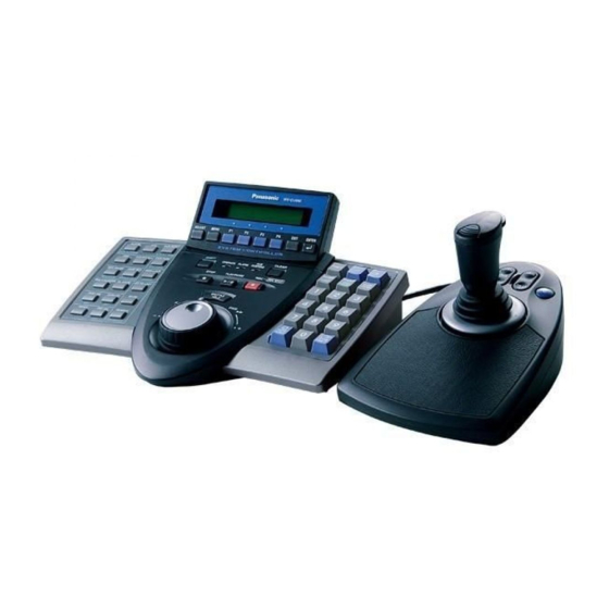
System controller
Hide thumbs
Also See for WV-CU650:
- Operating instructions manual (88 pages) ,
- Product catalog (125 pages) ,
- Addendum (48 pages)

Related Manuals for Panasonic WV-CU650


Summary of Contents for Panasonic WV-CU650
-
Page 1: Operating Instructions
Operating Instructions System Controller WV-CU650 Model No. Before attempting to connect or operate this product, please read these instructions carefully and save this manual for future use. - Page 2 (servicing) instructions in the litera- Model No. WV-CU650 ture accompanying the appliance. Serial No. SA 1966 WARNING: To prevent fire or electric shock hazard, do not expose this appliance to rain or moisture. The apparatus shall not be exposed to...
-
Page 3: Important Safety Instructions
IMPORTANT SAFETY INSTRUCTIONS 1) Read these instructions. 2) Keep these instructions. 3) Heed all warnings. 4) Follow all instructions. 5) Do not use this apparatus near water. 6) Clean only with dry cloth. 7) Do not block any ventilation openings. Install in accordance with the manufacturer's instructions. 8) Do not use near any heat sources such as radiators, heat registers, stoves, or other apparatus (including amplifiers) that produce heat. -
Page 4: Table Of Contents
CONTENTS IMPORTANT SAFETY INSTRUCTIONS ......3 CAMERA CONTROL ............40 ■ Camera Panning/Tilting Control ........40 PREFACE ................5 ■ Zooming Control ............40 FEATURES ................5 ■ Lens Iris Control ............40 PRECAUTIONS ..............6 ■ Lens Focus Control ...........40 LIMITATION OF LIABILITY ..........6 ■ Preset Position Control ..........41 DOCUMENT CONVENTION ..........7 ■... -
Page 5: Preface
PREFACE This product, System Controller WV-CU650, is designed for setup and operation of cameras and other system units installed in a surveillance system. FEATURES • This product can control cameras, matrix switchers, and recording devices such as digital disk recorders. -
Page 6: Precautions
OR CAUSE INCLUDING ANY FAILURE OR PROBLEM SON, EXCEPT FOR CERTAIN WARRANTY PROGRAM OF THE PRODUCT; OFFERED BY THE LOCAL DEALER OF PANASONIC, FOR THE CASES INCLUDING BUT NOT LIMITED TO BELOW: (5) ANY PROBLEM, CONSEQUENTIAL INCONVENIENCE, OR LOSS OR DAMAGE, ARISING OUT OF THE SYS- (1) ANY DAMAGE AND LOSS, INCLUDING WITHOUT LIM- TEM COMBINED BY THE DEVICES OF THIRD PARTY. -
Page 7: Document Convention
DOCUMENT CONVENTION This document uses the following convention when describing the use and operation of this unit. System controller: Panasonic System Controller WV-CU650 Caution(s): Caution statements identify conditions or practices that could result in damage to this product or injury. -
Page 8: Major Operating Controls And Their Functions
MAJOR OPERATING CONTROLS AND THEIR FUNCTIONS ■ Main Unit ● Front View $3 3 q w e WV-CU650 ADJUST MENU EXIT ENTER SYSTEM CONTROLLER SHIFT CLEAR OPERATE ALARM SUSPEND STOP PLAY/PAUSE REC STOP SHUTTLE HOLD — @6 @8 @8 t Clear button (CLEAR) Note: Although printed on the template, some button func- tions are not mentioned here. - Page 9 o Camera function/System function button @0 Auxiliary 1 ON/OFF button (AUX 1 ON/OFF) (CAM FUNC/SYS FUNC) • Turns on an auxiliary device (AUX 1). • Recalls a function of camera by the function number. • When you press while holding down the SHIFT button, •...
- Page 10 @8 Shuttle hold button (SHUTTLE HOLD) #8 LCD (Liquid Crystal Display) • If you press this button while rotating the shuttle ring, Displays the numbers of unit, monitor and camera cur- playback speed will be maintained even after removing rently selected. The LCD also displays the functions a hand from the shuttle ring.
- Page 11 ● Rear View MODE CONTROLLER SERIAL DC9V IN JOYSTICK DATA $4 Joystick connector (JOYSTICK) $8 Controller Number switch (CONTROLLER NO.) This connector is used for connection with the joystick. When two or more system controllers are connected in the system, this switch determines the unit number of $5 Serial port (SERIAL) each controller.
-
Page 12: Joystick Unit
■ 3D Joystick Unit This joystick unit is used to operate combination cameras and pan/tilt heads manually. OPEN IRIS FOCUS CLOSE NEAR %0 Top button %3 Focus control buttons (FOCUS NEAR, FAR) The top button is pressed to recall a function already These buttons adjust the lens focus of cameras assigned. -
Page 13: Lcd Display Descriptions
■ LCD Display Descriptions The following are examples of LCD display after login. Note: Some parts of LCD displays, described on this document, may differ from the actual status. ● Default Status (LCD Display After Login) Mon02 Cam016 HD316 q Monitor number •... - Page 14 ● Main Menu (Menu Functions) LCD MENU CAM 101 Camera Setup q Category e Function name The category of selected menu function is displayed. The name of selected menu function is displayed. w Function number The function number of selected menu function is dis- played.
- Page 15 ● Messages Displayed on the LCD Prohibited Invalid Mon02 Cam016 HD316 Prohibited Invalid • When you have tried an operation not authorized by the function level setting, camera level setting, or selected This message is displayed in the following circumstances. system unit, “Prohibited”...
-
Page 16: Installations And Connections
• • • PS·Data Monitor 1 10/0 To PS·Data ports Monitor 2 Digital Disk Recorder WJ-HD300 Series Modular cable (supplied) Used when adding other WV-CU650 system controllers (Available up to 3) System Controller WV-CU650 (Main unit) MODE SERIAL CONTROLLER DC9V IN... -
Page 17: Connection With The 3D Joystick Unit
■ Connection with the 3D Joystick Unit Connect the main unit and 3D joystick unit as follows. Bottom side Main unit 3D joystick unit Cable connector DOWN MODE CONTROLLER SERIAL JOYSTICK DATA DC9V IN Combination code label has been stuck on the bottom. -
Page 18: Setup Procedures (Hardware)
(Refer to p. 19.) ● Setting for Terminal Mode Note: Before performing WV-CU650 setups, you need to log into the system by entering the administrator pass- Set the MODE Switch #1 and #5 to ON. -
Page 19: Setup Procedures (Firmware)
SETUP PROCEDURES (FIRMWARE) ■ Administrator Password Entry Buttons pressed Setting Mode Description while the power-on If you log into the system in the administrator mode, 2, 4, and 6 All reset The communication PS·Data communication setting, all reset, operator pass- settings and word check. -
Page 20: All Reset
■ All Reset 4. Press the CAM (SET) button. If the password entered is correct, all the settings will When the all reset mode is activated, all of the following set- be reset to the factory default. tings will be reset to the factory default. All Reset All Reset •... - Page 21 3. Enter the administrator password. Wait time The password entered will be displayed as “∗” marks. PS Data Com. Setup • PS Data Com. Setup • Wait Time Off Admin Password ∗ ∗ ∗ ∗ ∗ The wait time until the data is sent again (Refer to p. 22 for Notes: details.) •...
- Page 22 4. Press the MON (ESC) button. 3. Select a desired parameter by rotating the JogDial The selected parameter will be determined, and the or pressing the + or – button. LCD display will return from the editing mode to the dis- You can select the desired parameter from “1”...
- Page 23 ● Group Address Setting for System 3. Select "A" by rotating the JogDial or pressing the + or – button. Controller PS Data Com. Setup • Note: Remain the factory default. When you have mistaken- Sys G—Adr.A ly changed the setting, recover the factory default as follows.
-
Page 24: To Change The Administrator Password
■ To Change the Administrator 7. Enter a new administrator password. Password Admin Password Setup ∗ ∗ ∗ ∗ ∗ You can change the administrator password. The factory New Password default is “650”. 8. Press the CAM (SET) button. ● Operation “New Password”... -
Page 25: Database Copy
(Refer to p. 20 PS·Data The LCD display of destination system controller(s) Communication Setting.) become(s) as follows. • This function is available only among WV-CU650 System Controllers. You cannot copy the PS·Data data- Data Base Rx Mode base to other models, such as WV-CU360C. -
Page 26: Ps·data Operator Password Check
The LCD display of destination system controller(s) 5. To search a desired operator, rotate the JogDial. becomes as follows. The user ID and password of Operator 1 to 16 will appear interchangeably. Data Base Rx Mode 6. Turn off the power. Completed Sum=1733 Operator 1 information... -
Page 27: Before Operation
BEFORE OPERATION ■ Power-on ■ Power-off Before operation, confirm system composition. After operation, power off the system controller as follows. Depending on system composition, some functions may be unavailable. 1. Log out from the system. (Refer to p. 30.) 1. Plug the supplied AC adapter into an AC 120 V out- 2. -
Page 28: Basic Operation Flow
■ Basic Operation Flow Login Login Unit selection System Unit Selection Monitor selection Operation Monitor Selection (Multiscreen segment switching and sequence Camera selection System Unit Camera Selection Setup and Operation Operation (Panning, Tilting, and zooming, etc.) Camera setup and control Logout at the end of operation... -
Page 29: Operation Start (Login)
● Button Buzzer Setting User ID __650 You will perform the setting whether to activate a sound when a button is pressed. Select the desired parameter by rotating the JogDial. Notes: • To delete a character, press the CLEAR button. Buzzer Operation •... -
Page 30: If You Have Forgotten The Login Password
■ If You Have Forgotten the Login ■ Operation End (Logout) Password You need to log out from the system: • When finishing operation and turning off the power Refer to the system administrator. • When changing an operator 1. During the login status, press the LOGOUT button while holding down the SHIFT button. -
Page 31: Unit Selection
UNIT SELECTION ■ Recorder Selection To control the system, you need to select a desired unit (system unit, recorder, monitor, or camera) at the begin- Notes: ning. • In advance, you need to set HDD-unit maps. (Refer to p. 67 Associating Recorder Numbers with Unit Numbers.) ■... -
Page 32: Monitor Selection
■ Monitor Selection Note: If camera numbers are associated with unit num- bers, you can skip system unit selection. (Refer to When two or more monitors are connected to a system unit, p. 66 Associating Camera Numbers with Unit you can select a desired monitor. Numbers.) When monitor selection is unavailable, “Mon- -“... -
Page 33: System Unit Control
SYSTEM UNIT CONTROL ■ Tour Sequence/Group Sequence The following are the procedures to control system units (including recorders). Sequence monitoring is the function to switch camera images automatically, according to the order registered in the system unit. The following procedure is available when ■... -
Page 34: System Function Control
1. Select a desired monitor. (Refer to p. 32 Monitor Selection.) 2. To toggle the OSD information, press the OSD button. Note: OSD information differs depending on system units. Refer to the operating instructions of system units. ■ System Function Control You can recall system functions (functions of system units) by pressing the corresponding function numbers. -
Page 35: Recorder Control
RECORDER CONTROL From this system controller, you can control digital disk Multiscreen display: Refer to p. 9 !7 Multiscreen recorders supporting PS·Data. You will control a recorder in selection button. the status in which a recorder has been selected. Marking (WJ-HD300 Series only): Refer to p. 9 !8 5 Mark button. - Page 36 CAM (SET) button: Determines the selected parameter Available buttons and functions or searching filter setting. F1 button: Thumb or List MON (ESC) or EXIT button: Closes the search list dis- Changes the monitor display between the recording event play. list window and thumbnail menu. <3D joystick unit>...
- Page 37 3. To determine the filter setting, press the CAM (SET) but- F2 button: Group ton of main unit or top button of 3D joystick unit. The selected group is switched by rotation. The searching filter window will appear on the active monitor, and the selected camera channels will be dis- F3 button: Alm played on the window.
-
Page 38: Time & Date Search Playback
4. Enter the desired date and time by performing either of Notes: the following. • To quit search playback, press the MON (ESC) or EXIT • Rotate the JogDial clockwise or counterclockwise. button. Live image will be displayed again on the moni- •... -
Page 39: Other Available Functions
2. Select a desired group to play back by rotating the JogDial. 3. Press the PLAY/PAUSE or CAM (SET) button again. The image on the specified date and time will be played back on the active monitor. Note: Image to be played back differ depending on recorders. -
Page 40: Camera Control
CAMERA CONTROL ■ Lens Iris Control You can control cameras from this system controller. The following procedure is available when a selected cam- era has an adjustable lens iris. ■ Camera Panning/Tilting Control 1. Select a system unit, monitor, and desired camera. (Refer to p. -
Page 41: Preset Position Control
■ Preset Position Control ■ Home Position Control Preset position is the function to register camera monitoring Home position is the default preset position. You can move positions (preset positions) associated with position num- the camera to the home position only by pressing the PRE- bers. -
Page 42: Camera Position Control
■ Camera Position Control Mon02 Cam128 HD316 Camera position is the association of camera numbers and preset position numbers. Up to 1 000 camera positions are registrable in the system, and you can move a desired camera to a desired preset position only by entering a cam- era position. -
Page 43: Defroster Control
■ Defroster Control ■ Other Functions The following procedure is available when a selected cam- You can control the following functions by pressing the era (housing) is equipped with a defroster. function buttons (F1 to F8). Refer to p. 55 MENU FUNC- TION DETAILS. -
Page 44: Alarm Control
ALARM CONTROL ■ System Controller Behavior Note: You cannot suspend each alarm input one by one. The alarm inputs to all the system units will be during the Alarm Mode suspended all together. When an alarm signal is input to cameras or system units, this system controller is notified that an alarm has been activated. - Page 45 <Joystick unit> 2. Press the F1 button. Search Editing Area will appear on the Record List. 3D joystick upward (▲): Moves the cursor up. 3D joystick downward (▼): Moves the cursor down. 3D joystick to the left (t): Moves the cursor to the left. DATE MAY29.00 ALL GROUP 3D joystick to the right (s): Moves the cursor to the...
- Page 46 ● Operation (WJ-HD200 Series) 4. Enter the desired date and time by performing either of the following. • Rotate the JogDial clockwise or counterclockwise. • Press the + or – button. Alarm Recall HD200 Edit 5. Repeat Step 3 and 4 to edit Search Editing Area. 6.
-
Page 47: Menu Function Descriptions
MENU FUNCTION DESCRIPTIONS You can assign frequently-used menu functions (system functions and camera functions, etc.) to the F1 to F8 button of system controller. (=Button function) In addition, you can also assign the menu functions to the A, B and top buttons of 3D joystick unit. -
Page 48: Menu Function Categories
■ Menu Function Categories Auto Pan Setup Menu functions are classified in the following categories. LCD MENU CAM 105 Select a desired function for assignment or operation. Auto Pan Setup ● Camera Functions (CAM) You will perform the auto pan setting of camera. Camera Setup Note: Refer to the operating instructions of camera for details on the auto pan function. - Page 49 ● System Functions (SYS) You will select the first and last camera channel to perform camera cleaning. System Setup Time & Date Type LCD MENU SYS 301 System Setup LCD MENU CNT 402 Time&Date Type You will open the setup menu of system unit and change the settings.
- Page 50 Cam-Unit Map Camera Sequence LCD MENU CNT 408 J/S MENU Cam-Unit Map Camera Sequence You will register cam-unit maps (the association of camera The camera sequence function of selected camera will be numbers and unit numbers). activated. HDD-Unit Map Camera Sort LCD MENU CNT 409 J/S MENU...
-
Page 51: To Recall Menu Functions
Camera +1 J/S MENU Multi 9-Seg J/S MENU Camera +1 J/S MENU Multi 10-Seg The image of camera with the higher channel number will be displayed. J/S MENU Camera –1 Multi 13-Seg J/S MENU J/S MENU Camera -1 Multi 16-Seg The image of camera with the lower channel number will be The screen of monitor connected to the selected system displayed. -
Page 52: Factory Default Setting Of Button Functions And Joystick Button Functions
4. Press the ENTER or CAM (SET) button. F4: Patrol Learn The sub menu of selected function will appear on the LCD. Patrol Learn Start Stop System Setup F5 (SHIFT + F1): System Setup 5. Perform the operations to activate the selected function. The operating procedure differs depending on each System Setup function. -
Page 53: To Assign Menu Functions To Joystick Function Buttons
Notes: LCD MENU CAM 101 • The illustration is an example in which Camera Camera Setup Function Number 1 is pressed. • Refer to the operating instruction of camera for details on camera function. 2. Select a desired function. • Refer to the operating instruction of system unit for Select a desired category by rotating the shuttle ring. -
Page 54: To Check Button Functions And Joystick Button Functions
■ To Check Button Functions and Joystick Button Functions You can check the functions assigned to the function (F1 to F8) buttons and joystick function (A, B, and top) buttons. 1. Press the MENU button while holding down the SHIFT button. -
Page 55: Menu Function Details
MENU FUNCTION DETAILS ■ Camera Functions Top button: Determines the selected parameter and moves to the sub menu. ● Camera Setup 4. Press the F2 button. You can display the setup menu of selected camera on the The setup menu of selected camera will be closed, and active monitor. - Page 56 2. Press the F1 button. BW Mode The patrol learn setup will start. On Off Auto1 Auto2 3. Perform desired camera operations by moving the 3D joystick or zoom wheel controller, etc. The following controls are available for patrol learn. •...
-
Page 57: Recorder Functions
● Auto Pan Setup and Activation 2. Press one of the F1 to F4 buttons. The specified disk will be selected. You will set up and activate the auto pan function. The cam- era can pan between the start and end points you will set. Available buttons and functions F1: Nr-A To set the start and end point of auto pan... -
Page 58: System Functions
● Filtering ON/OFF Note: To cancel the numeric entry, press the CLEAR button. (WJ-HD300 Series Only) During the filtering playback, the searching filter will be 3. Press the F1 button. temporarily canceled or recovered. • Playback picture will be displayed on the multi- screen monitor. - Page 59 Available controls and functions 2. Press the F1 or F2 button. The monitor display will be changed between playback <Main unit> pictures and live images, and “s” mark will light up Shuttle ring clockwise: Moves to the next page. beside the activated setting. Shuttle ring counterclockwise: Moves to the previous page.
-
Page 60: Controller Functions
3. Press the F1 button. Note: To return the cursor to the previous item, rotate • The still mode will be activated for the selected the shuttle ring counterclockwise or move the 3D camera channel. joystick to the left. • The specified camera channel will blink on the LCD for a few seconds, and the LCD display will return 5. - Page 61 3. Rotate the shuttle ring clockwise or move the 3D joy- Display pattern Display Example stick to the right. DD/MM/YYYY HH:MM 24 21/08/2001 22:55 24 * MM/DD/YYYY HH:MM 24 08/21/2001 22:55 24 4. To activate auto login, select an operator DD/Mmm/YYYY HH:MM 24 21/Aug/2001 22:55 24 (Operator 1 to 16) by performing the following.
- Page 62 2. Press the CLEAR button. 4. Enter a user ID by pressing the numeric buttons. “Clear OK?” will appear on the LCD. “1” to “99999” are available for the user ID number. Operator07 Auto Login/out User ID= Cont No.6 Clear OK? Note: To cancel deactivating auto login, press the EXIT Note: If you have entered a wrong user ID, press the or MON (ESC) button.
- Page 63 10. Set the camera level by performing either of the follow- 2. Press the CLEAR button. ing. “Clear OK?” will appear on the LCD. • Rotate the JogDial clockwise or counterclockwise. • Press the + or – button. Operator Setup Operator07 Clear OK? Operator07 Camera Level...
- Page 64 4. Select a desired function by performing one of the fol- Function Table2 lowing. 08 IRIS OPEN/CLOSE=D • Rotate the JogDial clockwise or counterclockwise. • Press the + or – button. • Enter the function number with the numeric buttons. Note: To change the settings of other functions, repeat The function setting will appear on the LCD.
- Page 65 Camera Table3 Camera Table3 Cam001 Memory 4. Select a desired camera channel by performing one of ● Camera Position Registration or the following. • Rotate the JogDial clockwise or counterclockwise. Clearing • Press the + or – button. This system controller can memorize camera position num- •...
- Page 66 ● Associating Camera Numbers with 6. Select a desired preset position number by performing either of the following. Unit Numbers • Rotate the JogDial clockwise or counterclockwise. • Press the + or – button. You can register camera-unit maps (the association of cam- era numbers and unit numbers).
- Page 67 ● Associating Recorder Numbers with Note: To return to Step 3, rotate the shuttle ring coun- terclockwise or move the 3D joystick to the left. Unit Numbers 5. Select a desired unit number by performing either of the You can register HDD-unit maps (the association settings of recorder numbers and unit numbers).
- Page 68 6. Press the ENTER or CAM (SET) button again. LCD Title F1-F4 The specified recorder number and unit number will be set for the selected HDD-unit map. “Memory” will appear on the LCD for a few seconds, When "F1 — F4" is selected and the LCD display will return to Step 1.
-
Page 69: Joystick Button Functions
■ Joystick Button Functions ● System Function You can recall system functions by entering function num- If you register a joystick button function to a function button bers from this system controller. or joystick function button, you can activate the associated function only with pressing the button. - Page 70 ● Auto Pan ● Camera Sort You can activate the auto pan mode for the selected cam- You can activate the auto sort mode for the selected cam- era. era. Note: Refer to the operating instruction of camera for Note: Refer to the operating instruction of camera for details of this function.
- Page 71 ● Home Position ● Iris Reset You can move the selected camera to the home position. You can activate the iris reset function for the selected camera. Note: Refer to the operating instruction of camera for details of this function. Note: Refer to the operating instruction of camera for details of this function.
- Page 72 ● Camera –1 HD300 A—B Repeat 512 You can change the camera image on the monitor to the lower channel. 1. Display “Camera –1” sub menu. (Refer to Step 1 to 4 of p. 51 To Recall Menu Functions.) Notes: •...
- Page 73 7-segment multiscreen display HD500 Copy Multi 7-Seg “Enter F1 Button” ● Alarm Search (WJ-HD200 Series / WJ-HD100 Series) You can move the playback start point to the next alarm 9-segment multiscreen display record of recorded image data. Note: Refer to the operating instruction of recorder for Multi 9-Seg details of this function.
-
Page 74: Troubleshooting
TROUBLESHOOTING Check the following before requesting repair. If a trouble cannot be corrected even after checking and trying remedy, contact your dealer. Problem Check item and Remedy Reference The power of system controller is not The AC adapter may be disconnected Refer to p. - Page 75 Problem Check item and Remedy Reference Buzzer sound is not heard. The buzzer may be set to OFF. Check Refer to pp. 28 or 29. the setting. You cannot activate any functions even The cable may be disconnected from Refer to p. 17. when pressing the A, B, or top button of either the system controller and 3D joy- the 3D joystick unit.
-
Page 76: Specifications
SPECIFICATIONS ● System Controller Power Source: 9 V DC, 300 mA (using the supplied AC adapter) Power Source (Supplied AC Adapter): 120 V AC, 60 Hz, 200 mA Data Output/Input Port: 6-conductor modular jack (RS-485, Full duplex) x2 Serial port: 9-pin D-sub connector Controller Number: 1 to 8 (rotary switch) - Page 78 Security Systems Group PANASONIC SALES COMPANY www.panasonic.com/cctv DIVISION OF MATSUSHITA ELECTRIC OF PUERTO RICO INC. Executive Office: One Panasonic Way 3E-7, Secaucus, New Jersey 07094 San Gabriel Industrial Park 65th Infantry Ave. KM. 9.5 Carolina, Zone Office P.R. 00985 (809)750-4300 Eastern: One Panasonic Way, Secaucus, NJ 07094 (201) 348-7303 Central: 1707 N.Randal Road, Elgin, IL 60123 (847) 468-5205...
- Page 79 • The connection details are the same as System Controller WV-CU360C/CJ. Refer to the operating instructions of matrix switcher . • To connect System Controller WV-CU650 to Digital Disk Recorder WJ-HD300 Series or WJ-HD220 Series via the matrix switcher, refer to pp. 37 to 39.
- Page 80 Note: The factory default setting is 150. Note: If you want to save the power consumption, discon- nect the DC 9 V plug from the controller, and remove 4. To select your registered password (up to 5 digits), the AC adapter from the AC outlet. press the numeric buttons, then press the CAM (SET) button.
-
Page 81: Camera Selection
MONITOR SELECTION AND CAMERA SELECTION ● Releasing Priority Lock Note: This section describes the terminal mode. To operate in the PS·Data mode, refer to the operating instructions. 1. Select the desired monitor. (Refer to Monitor Selection.) After the login procedure, the following operations are avail- 2. - Page 82 CAMERA CONTROL Note: This section describes the terminal mode. To operate 3. To adjust the lens zoom, move the zoom wheel con- troller to the right (TELE) or left (WIDE). in the PS·Data mode, refer to the operating instructions. Buttons and control for cameras or camera site accessories are located on the 3D joystick unit and the right side of main unit.
- Page 83 ■ Program Preset Position ■ Call Preset Position 1. Select the desired monitor and camera. (Refer to p. 3 1. Select the desired monitor and camera. (Refer to p. 3 Monitor Selection and p. 3 Camera Selection.) Monitor Selection and p. 3 Camera Selection.) 2.
- Page 84 CAMERA FUNCTION CONTROL ■ Camera Function (Shortcut Note: This section describes the terminal mode. To operate in the PS·Data mode, refer to the operating instructions. Function) The following function is available only when specified cam- eras with the camera function feature are used. ■...
- Page 85 ■ Patrol Learn and Play ■ Auto Pan Setup and Activation A routine of manual operations can be stored for a specific You will set up and activate the auto pan function. The cam- time and later reproduced repetitively. era can pan between the start and end points you will set. 1.
- Page 86 ■ Camera Panning Function ■ Changing to Black and White Images There are three panning modes available as follows: sequence mode, sort mode, and auto pan. (Refer to the This function gets the clear camera images on the monitor operating instructions of matrix switcher.) while shooting the objects under low light conditions.
- Page 87 CAMERA SITE ACCESSORIES CONTROL ● Auxiliary Control Note: This section describes the terminal mode. To operate in the PS·Data mode, refer to the operating instructions. 1. Select the desired monitor and camera. (Refer to p. 3 Monitor Selection and p. 3 Camera Selection.) 2.
- Page 88 RUNNING SEQUENCE ■ Group Sequence Note: This section describes the terminal mode. To operate in the PS·Data mode, refer to the operating instructions. The following function is available only if a group sequence been previously established WJ-SX150A Administrator Console. ■ Tour Sequence As described earlier, a group sequence determines the assignment of monitors and cameras.
- Page 89 MONITOR DISPLAY CONTROL ● Displaying All the Items Note: This section describes the terminal mode. To operate in the PS·Data mode, refer to p. 35. 1. Perform Step 1 of Displaying Each Item. 2. Hold down the SHIFT button. The LCD display will become as follows. ■...
- Page 90 2. Perform desired operations. 1. Select the desired monitor. (Refer to p. 3 Monitor Selection.) 2. Press the MENU button repeatedly until "System Status" appears on the LCD. 3. Press the F1 button. The SYSTEM STATUS table will appear on the active monitor as shown in the figure.
- Page 91 ■ Alarm History Table ■ Video Loss History Table There are 100 alarm records stored in chronological order There are 100 video loss detection records stored in in 10 pages of tables. chronological order in 10 pages of table. 1. Select the desired monitor. (Refer to p. 3 Monitor 1.
- Page 92 ALARM CONTROL ■ Operation during an Alarm Mode Note: This section describes the terminal mode. To operate in the PS·Data mode, refer to the operating instructions. While an alarm mode is active, the following are available from the system controller: •...
- Page 93 ■ Resetting the Alarm Inputs ■ Suspending the Alarm Inputs There are two alarm reset functions: Use this function when you do not want to be disturbed by • Alarm reset (resetting the alarm inputs per monitor) an alarm input, for example, during the setup procedures. •...
- Page 94 MULTIPLEXER OPERATIONS ● Multiscreen Sequence Multiplexer board WJ-SXB151 is an optional board. It enables multiscreen display, electronic zooming, still pic- Camera images are switched automatically in a sequence ture and multiscreen sequence. mode. It also enables the operation of Digital Disk Recorder WJ- The sequence mode (QUAD, 3+1, 8+1) is configurable HD100 Series or time-lapse VCR, when connected to them.
- Page 95 Series recorder or time-lapse VCR to the matrix switcher. Note: When a WJ-HD100 Series recorder or a Panasonic 1. Enter the recorder mode. (Refer to Step 1 to 3 of p. 16 time-lapse VCR is connected to the matrix switcher, Multiscreen Segment Switching.)
-
Page 96: Setup Menu
WJ-HD500 SERIES CONTROL (TERMINAL MODE) Matrix switcher can control Digital Disk Recorder WJ- <Main unit> HD500 Series. The following is the procedure of WJ-HD500 JogDial clockwise: Increments a parameter. Series SETUP MENU. JogDial counterclockwise: Decrements a parameter. CAM (SET) button: Executes the selections and dis- Notes: plays a submenu. - Page 97 ■ Controlling Digital Disk ● Multiscreen Segment Switching Recorder WJ-HD500 Series Multiscreen segment patterns are configurable through WJ- HD500 SETUP. The following are the operating procedures of WJ-HD500 (Refer to the recorder’s operating instructions.) Series via system controller. 1. Enter the recorder mode. (Refer to Recorder Mode.) Note: Refer to the operating instructions of Digital Disk Recorder WJ-HD500 Series for details.
- Page 98 ● Search Playback • To skip to the previous/next record during the play- back, move the JogDial clockwise or counterclock- You can search playback images using the Record List or wise. (Refer to the recorder’s operating instructions Thumbnail Display. Every time you press the SEARCH/T&D for the description of record.) SEARCH button, the monitor display will change as follows.
- Page 99 • Record List/Thumbnail Display Note: The PLAY/PAUSE button is deactivated in the search editing area. You can operate the Record List or Thumbnail Display by referring to the recorder’s operating instructions. In addi- tion, the following operations from the system controllers ●...
- Page 100 WJ-HD300 SERIES CONTROL (TERMINAL MODE) Matrix switcher can control Digital Disk Recorder WJ- + button: Increments a parameter. HD300 Series. The following is the procedure of WJ-HD300 – button: Decrements a parameter. Series SETUP MENU. MON (ESC) button: Returns to SETUP MENU or the previous menu.
- Page 101 ● Normal Playback Available buttons and functions (Common) F1 button: Thumb or List The operations are the same as WJ-HD500 Series. (Refer to Changes the monitor display between the recording p. 19.) event list window and thumbnail menu. Note: Refer to the recorder’s operating instructions for details and other playback modes.
- Page 102 • Date-and-time Search Playback 3. Select a desired searching filter by moving the joystick rightward or leftward. The recorded images can be searched for through the date and time. 1. Enter the recorder mode. (Refer to p. 19 Recorder TIME&DATE CAMERA REC EVENT TEXT...
- Page 103 Searching filter windows Available controls and functions (REC EVENT FILTER- ING window) Available controls and functions (TIME&DATE FILTER- ING window) REC EVENT FILTERING EMERGENCY ■ TIME&DATE FILTERING TERMINAL START COMMAND VIDEO LOSS MANUAL SCHEDULE SET : [ SET ] CANCEL : [ ESC ] SET : [SET] CANCEL : [ESC] <Main unit>...
- Page 104 VMD SEARCH TIME&DATE APR.25.03*12:34:56 AM 01ch APR.25.03*12:34:56 AM 01ch APR.25.03*12:34:56 AM 01ch APR.25.03*12:34:56 AM 01ch APR.25.03*12:34:56 AM 01ch APR.25.03*12:34:56 AM 01ch APR.25.03*12:34:56 AM 01ch APR.25.03*12:34:56 AM 01ch APR.25.03*12:34:56 AM APR.25.03*12:34:56 AM TOTAL 12345 TIME&DATE SEARCH REC EVENT SEARCH VMD SEARCH MARK 3.
- Page 105 12. Select the sensitivity by moving the joystick upward or 17. Press the PLAY button. downward. The playback of selected recording event will start. The sensitivity will be applied. OFF: The motion detector is not activated on the 18. To exit the search mode, press the MON (ESC) or EXIT camera channel.
- Page 106 Available controls and functions 4. When you specify a disk, the search list display will appear on the active monitor, and "Search Mode" menu <Main unit> Shuttle ring clockwise: Moves to the next page. will appear on the LCD. Then, perform the search play- Shuttle ring counterclockwise: Moves to the previous back operation.
- Page 107 ■ Marking Note: If the recorder is WJ-HD300 Series, "B" mark will light up beside "Off" in the default status. 1. Enter the recorder mode. (Refer to p. 19 Recorder Mode.) 3. Press the F2 button. The searching filter will be canceled, and "B" mark will 2.
- Page 108 WJ-HD200 SERIES CONTROL (TERMINAL MODE) ● Manual Recording Matrix switcher can control Digital Disk Recorder WJ- HD200 Series. The following is the procedure of WJ-HD200 The operations are the same as WJ-HD500 Series. (Refer to Series SETUP MENU. p. 20.) Notes: Note: Refer to WJ-HD200 Series Operating Instructions for •...
- Page 109 ● Electronic Zooming (EL-ZOOM) 3. Press the numeric buttons or +/– button to enter the desired date and time. The operations are the same as WJ-HD500 Series. (Refer to The cursor can be adjusted by moving the 3D joystick p. 21.) rightward or leftward.
- Page 110 WJ-HD100 SERIES CONTROL (TERMINAL MODE) ● Manual Recording Digital Disk Recorder WJ-HD100 Series are operable with the system controller, when the Multiplexer board is The operations are the same as WJ-HD500 Series. installed in the matrix switcher. Refer to p. 20. Note: Before the use, it is necessary to install the Multi- plexer board in the matrix switcher, connect the ●...
- Page 111 3. Press the numeric buttons or +/– button to enter the desired date and time. The cursor can be adjusted by moving the 3D joystick rightward or leftward. 4. Press the PLAY/PAUSE button. After the search through the date and time, the recorded image will be played. 5.
- Page 112 SETUP MENU. (Refer to the operating instructions ● Manual Recording of matrix switcher.) The operations are the same as WJ-HD500 Series. The following is the procedure of a Panasonic model time- Refer to p. 20 Manual Recording. lapse VCR. ● Stopping REC ONLY Alarm Recording ■...
- Page 113 4. To display the spot picture, press the numeric buttons corresponding to the desired camera number, then The following is the procedure of a non-Panasonic model press the CAM (SET) button. Then, the active monitor time-lapse VCR.
- Page 114 WJ-HD500/300/200/100 SERIES CONTROL (PS·DATA) ■ Functions Only Available with The details on recorder control are described in WV-CU650 Operating Instructions. However, when the system con- WJ-HD200 Series/WJ-HD100 troller (WV-CU650) is connected to recorders via the matrix Series switcher (WJ-SX150 Series), the following differences will occur.
- Page 115 (2) ADDENDUM FOR MATRIX SWITCHER WJ-SX150 SERIES: TO USE DIGITAL DISK RECORDER WJ-HD300 SERIES/WJ-HD220 SERIES SYSTEM CONNECTIONS AND SETUPS (WJ-HD300 SERIES/WJ-HD220 SERIES) ■ Connection with Digital Disk Recorder WJ-HD300 Series Notes: • Refer to service personnel for details on the connection with a recorder to operate via LAN or the Internet. •...
- Page 116 ● To Control a Recorder and Cameras via the Network The following is the description of the connection between a recorder and this unit to control the recorder and cameras via the network. 1. Set the unit address of the recorder to 5 or larger. (Refer to the recorder’s operating instructions.) 2.
- Page 117 ● PS·Data Connection 1. Set the unit address of the recorder to 5 or larger. 2. Set the [Camera control] setting to “PSD” for all cameras in SETUP MENU of the recorder. 3. Connect the unit’s CAM OUT 1 to 16 connectors to the recorder’s VIDEO IN 1 to 16 connectors with a coaxial cable. 4.
- Page 118 ● Settings of Administrator Console and SETUP MENU(OSD) When WJ-SX150A Administrator Console is Ver. 2.03 or later Select “HD300”. When the firmware of this unit is Ver. 2.03 or later. Select “HD300” for “CONTROL” in 600 RECORDER of SETUP MENU(OSD). 600 RECORDER CONTROL EXT IN...
- Page 119 WJ-HD300 SERIES CONTROL (WV-CU650 TERMINAL MODE) Refer to p. 22 WJ-HD300 SERIES CONTROL (TERMINAL MODE). WJ-HD300 SERIES CONTROL (WV-CU650 PS·DATA) Refer to p. 36 and the operating instructions of system controller.
- Page 120 This document describes operations applicable to WJ- HD300 Series only. • You cannot control the following functions from System Controller WV-CU360C and WV-CU360CJ. (It is recom- mended to use System Controller WV-CU650.) • A – B repeat playback DOWN • GO TO LAST •...
- Page 121 4. To determine the filter setting, press the CAM (SET) but- Joystick: Moves the cursor. ton. NEXT or PREV button: Changes a parameter. The searching filter window will be displayed on the CAM (SET) button: Executes the filtering. monitor. MON (ESC) button: Cancels the filtering and returns to the upper menu.
- Page 122 3. Press the CAM (SET) button. 8. Move the "+" mark to another desired area with the joy- The VMD search window will be displayed on the moni- stick, and then press the CAM (SET) button again. The tor. end point of motion detection area will be determined. ■...
- Page 123 • Marking search ■ VMD SEARCH ANY AREA The recording time of the recorded images with a marked MASKING DURATION point will be displayed in a list or a thumbnail. For playback, VECTOR you will select the desired recording time to play. (Refer to the recorder's operating instructions for details on marking.) DURATION 1.
- Page 124 WJ-HD300 SERIES CONTROL (WV-CU360C/CJ PS·DATA) Available operations are in common with WJ-HD500 Series. (Refer to the unit's operating instructions.) COMMUNICATION PROTOCOL (FOR USERS OF WJ-HD300 SERIES) The following commands have been described in the operating instructions of this unit (matrix switcher). However, while Digital Disk Recorder WJ-HD300 Series are being connected to the unit, these commands will be changed as follows.
- Page 125 The following commands have been newly added. These commands are available only while Digital Disk Recorder WJ-HD300 Series are being connected to the unit. Recorder Control Transmission Command Item Response (ASCII) Parameter (ASCII) (ASCII) Disk selection CMD:RmmDSn ANS:RmmDS mm=Monitor No. n=0 HDD normal/event recording sector n=1 HDD copy sector n=2 Disk connected to COPY 1...
- Page 126 Security Systems Group PANASONIC SALES COMPANY www.panasonic.com/cctv DIVISION OF MATSUSHITA ELECTRIC OF PUERTO RICO INC. Executive Office: One Panasonic Way 3E-7, Secaucus, New Jersey 07094 San Gabriel Industrial Park 65th Infantry Ave. KM. 9.5 Carolina, Zone Office P.R. 00985 (809)750-4300 Eastern: One Panasonic Way, Secaucus, NJ 07094 (201) 348-7303 Central: 1707 N.Randal Road, Elgin, IL 60123 (847) 468-5205...