Table of Contents
Advertisement
Quick Links
Advertisement
Table of Contents

Related Manuals for Supermicro X13SEED-F


Summary of Contents for Supermicro X13SEED-F
- Page 1 X13SEED-F/-SF USER’S MANUAL Revision 1.0...
- Page 2 State of California, USA. The State of California, County of Santa Clara shall be the exclusive venue for the resolution of any such disputes. Supermicro's total liability for all claims will not exceed the price paid for the hardware product.
- Page 3 SuperEdge product line and addresses Telco, Cloud, and IoT embedded needs with a short depth, high density Edge server solution. The X13SEED-F supports a 1GbE RJ45 LAN port, and the X13SEED-SF supports a 1G SFP port. Note that this motherboard is intended to be installed and serviced by professional technicians only.
- Page 4 Super X13SEED-F/-SF User's Manual Contacting Supermicro Headquarters Address: Super Micro Computer, Inc. 980 Rock Ave. San Jose, CA 95131 U.S.A. Tel: +1 (408) 503-8000 Fax: +1 (408) 503-8008 Email: Marketing@supermicro.com (General Information) Sales-USA@supermicro.com (Sales Inquiries) Government_Sales-USA@supermicro.com (Gov. Sales Inquiries) Support@supermicro.com (Technical Support) RMA@supermicro.com...
-
Page 5: Table Of Contents
Preface Table of Contents Chapter 1 Introduction 1.1 Checklist ..........................8 X13SEED-F Quick Reference ...................13 X13SEED-SF Quick Reference ..................14 Quick Reference Table ......................15 Motherboard Features .......................16 1.2 Processor and Chipset Overview ..................19 1.3 Special Features ........................19 Recovery from AC Power Loss ..................19 1.4 System Health Monitoring ....................20... - Page 6 Super X13SEED-F/-SF User's Manual 2.3 Motherboard Installation .....................31 Tools Needed ........................31 Location of Mounting Holes ....................31 Installing the Motherboard....................32 2.4 Memory Support and Installation ..................33 Memory Support ........................33 General Guidelines for Optimizing Memory Performance ..........34 DIMM Installation ......................35 DIMM Removal .........................35 2.5 Rear Panel I/O Ports ......................36...
- Page 7 Preface Chapter 4 UEFI BIOS 4.1 Introduction .........................61 4.2 Main Setup .........................62 4.3 Advanced ..........................64 4.4 Event Logs ........................103 4.5 BMC ..........................105 4.6 Security ..........................109 4.7 Boot ..........................114 4.8 Save & Exit ........................116 Appendix A BIOS Codes A.1 BIOS POST Codes ......................118 Appendix B Software B.1 Microsoft Windows OS Installation ...................112 B.2 Driver Installation ......................114...
-
Page 8: Chapter 1 Introduction
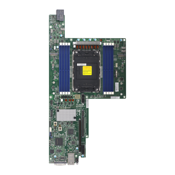
A secure data deletion tool designed to fully erase all data from storage devices can be found at our website: https://www.supermicro.com/about/policies/disclaimer.cfm?url=/wdl/ utility/Lot9_Secure_Data_Deletion_Utility/ • If you have any questions, contact our support team at: support@supermicro.com This manual may be periodically updated without notice. Check the Supermicro website for possible updates to the manual revision level. - Page 9 Chapter 1: Introduction Figure 1-1. X13SEED-F Motherboard Image Note: All graphics shown in this manual were based upon the latest PCB revision available at the time of publication of the manual. The motherboard you received may or may not look exactly the same as the graphics shown in this manual.
- Page 10 Super X13SEED-F/-SF User's Manual Figure 1-2. X13SEED-SF Motherboard Image Note: All graphics shown in this manual were based upon the latest PCB revision available at the time of publication of the manual. The motherboard you received may or may not look exactly the same as the graphics shown in this manual.
- Page 11 Chapter 1: Introduction Figure 1-3. X13SEED-F Motherboard Layout (not drawn to scale) FAN3 FAN4 JPME2 JBR1 JDBG1 FAN1 JVRM1 JSPD1 FAN2 JMD1 JMD2 JRK1 2280 2280 MT1_1 MT2_1 22110 22110 MT1_2 MT2_2 JSXB1C BIOS LICENSE X13SEED-F JNCSI1 REV:1.01 DESIGNED IN USA...
- Page 12 Super X13SEED-F/-SF User's Manual Figure 1-4. X13SEED-SF Motherboard Layout (not drawn to scale) FAN3 FAN4 JPME2 JBR1 JDBG1 FAN1 JVRM1 JSPD1 FAN2 JMD1 JMD2 JRK1 2280 2280 MT1_1 MT2_1 22110 22110 MT1_2 MT2_2 JSXB1C BIOS LICENSE X13SEED-SF JNCSI1 REV:1.01 DESIGNED IN USA...
-
Page 13: X13Seed-F Quick Reference
Chapter 1: Introduction X13SEED-F Quick Reference JPWR1 FAN3 FAN4 FAN3 FAN4 JPME2 JPME2 JBR1 JBR1 JDBG1 JDBG1 JVRM1 FAN1 FAN1 JVRM1 JSPD1 FAN2 JSPD1 FAN2 JMD1 JMD2 JMD1 JMD2 JRK1 DIMME1 DIMMA1 JRK1 DIMMF1 DIMMB1 DIMMG1 DIMMC1 DIMMH1 DIMMD1 2280... -
Page 14: X13Seed-Sf Quick Reference
Super X13SEED-F/-SF User's Manual X13SEED-SF Quick Reference JPWR1 FAN3 FAN4 FAN3 FAN4 JPME2 JPME2 JBR1 JBR1 JDBG1 JDBG1 JVRM1 FAN1 FAN1 JVRM1 JSPD1 FAN2 JSPD1 FAN2 JMD1 JMD2 JMD1 JMD2 JRK1 DIMME1 DIMMA1 JRK1 DIMMF1 DIMMB1 DIMMG1 DIMMC1 DIMMH1 DIMMD1... -
Page 15: Quick Reference Table
BMC Heartbeat LED Blinking Green: BMC Normal LED4 Unit Identifier LED Solid Blue: Unit Identified LED6 RJ45 Port Activity (X13SEED-F) Yellow: Port Activity Solid Green: 100 Mb/s LED7 RJ45 Link (X13SEED-F) Solid Amber: 1 Gb/s Yellow (Top): 1 Gb/s Link... -
Page 16: Motherboard Features
• Two PCIe 5.0 x4 M.2 M-Key 2280/22110 Slots Baseboard Management Controller (BMC) • Aspeed AST2600 Network • Intel I210 for single RJ45 GbE (X13SEED-F) or single 1G SFP (X13SEED-SF) Super I/O • Aspeed AST2600 Graphics • Aspeed AST2600 I/O Devices •... - Page 17 Chapter 1: Introduction Motherboard Features BIOS • 256Mb AMI BIOS® SPI Flash BIOS • ACPI, Plug and Play (PnP), SPI dual/quad speed support, riser card auto detection Power Management • ACPI power management (supports S5) • Power button override mechanism •...
- Page 18 Super X13SEED-F/-SF User's Manual Figure 1-5. System Block Diagram 4th Generation Intel Xeon Scalable Processor PCIe x16 Gen 5 SXB2 PE0[0-15] PCIe x32 Gen 5 PE1[0-15] SXB1 PE2[0-15] PCIe x1 Gen 3 Intel RJ45 Rear I/O 1G*1 I210 AT PCIe x4 Gen 5...
-
Page 19: Processor And Chipset Overview
1.2 Processor and Chipset Overview Built upon the functionality and capability of the 4th Generation Intel Xeon Scalable Processor and the C741 chipset, the X13SEED-F/-SF motherboard provides system performance, power efficiency, and feature sets to address the needs of next-generation computer users, and dramatically increases system performance for a multitude of server applications. -
Page 20: System Health Monitoring
Super X13SEED-F/-SF User's Manual 1.4 System Health Monitoring Onboard Voltage Monitors The onboard voltage monitor will continuously scan crucial voltage levels. Once a voltage becomes unstable, a warning is given, or an error message is sent to the screen. The user can adjust the voltage thresholds to define the sensitivity of the voltage monitor. -
Page 21: Acpi Features
Windows operating systems. For detailed information regarding OS support, refer to the Supermicro website. 1.6 Power Supply As with all computer products, a stable power source is necessary for proper and reliable operation. -
Page 22: Chapter 2 Installation
Super X13SEED-F/-SF User's Manual Chapter 2 Installation 2.1 Static-Sensitive Devices Electrostatic Discharge (ESD) can damage electronic com ponents. To avoid damaging your system board, it is important to handle it very carefully. The following measures are generally sufficient to protect your equipment from ESD. -
Page 23: Processor And Heatsink Installation
Thermal grease is pre-applied on a new heatsink. No additional thermal grease is needed. • Refer to the Supermicro website for updates on processor support. • All graphics in this manual are for illustrations only. Your components may look different. -
Page 24: Overview Of The Processor Carrier Assembly
Super X13SEED-F/-SF User's Manual Overview of the Processor Carrier Assembly The processor carrier assembly contains the Intel Xeon processor and a processor carrier. 1. Intel Xeon Processor 2. Processor Carrier Overview of the CPU Socket The CPU socket is protected by a plastic protective cover. -
Page 25: Overview Of The Processor Heatsink Module
Chapter 2: Installation Overview of the Processor Heatsink Module The processor heatsink module (PHM) contains a heatsink, a processor carrier, and the Intel Xeon processor. 1. Heatsink with Thermal Grease 2. Processor Carrier 3. Intel Xeon Processor Processor Heatsink Module (PHM) Bottom View... -
Page 26: Creating The Processor Carrier Assembly
Super X13SEED-F/-SF User's Manual Creating the Processor Carrier Assembly To install a processor into the processor carrier, follow the steps below: 1. Before installation, make sure the lever on the processor carrier is pressed down as shown below. 2. Hold the processor with the LGA lands (gold contacts) facing up. Locate the small, gold triangle in the corner of the processor and the corresponding hollowed triangle on the processor carrier. -
Page 27: Assembling The Processor Heatsink Module
Chapter 2: Installation Processor Carrier Assembly Assembling the Processor (Upside Down) Heatsink Module Triangle on the CPU After creating the processor carrier assembly for the processor, mount it onto the heatsink to create the processor heatsink module (PHM): 1. Note the label on top of the Thermal grease heatsink, which marks the airflow Triangle on the... -
Page 28: Preparing The Cpu Socket For Installation
Super X13SEED-F/-SF User's Manual Preparing the CPU Socket for Installation This motherboard comes with a plastic protective cover installed on the CPU socket. Remove it from the socket to install the Processor Heatsink Module (PHM). Gently pull up one corner of the plastic protective cover to remove it. -
Page 29: Installing The Processor Heatsink Module
Chapter 2: Installation Installing the Processor Heatsink Module After assembling the Processor Heatsink Module (PHM), install it onto the CPU socket: 1. Align pin 1 of the PHM with the printed triangle on the CPU socket. See the left image below. -
Page 30: Removing The Processor Heatsink Module
Super X13SEED-F/-SF User's Manual Removing the Processor Heatsink Module Before removing the processor heatsink module (PHM) from the motherboard, shut down the system and then unplug the AC power cord from all power supplies. Then follow the steps below: 1. Use a T30 Torx-bit screwdriver to loosen the four screws. -
Page 31: Motherboard Installation
JDBG1 FAN1 JVRM1 JSPD1 FAN2 JMD1 JMD2 JRK1 2280 2280 MT1_1 MT2_1 22110 22110 MT1_2 MT2_2 JSXB1C BIOS LICENSE X13SEED-F JNCSI1 REV:1.01 DESIGNED IN USA JIPMB1 JPFR3 JPFR2 JP13 JBM1 JPT1 JPL1 JCP1 JPFR1 JLAN1 MH10 MH11 MH12 JKVM1 LED4... -
Page 32: Installing The Motherboard
Super X13SEED-F/-SF User's Manual Installing the Motherboard 1. Install the I/O shield into the back of the chassis, if applicable. 2. Locate the mounting holes on the motherboard. See the previous page for the location. 3. Locate the matching mounting holes on the chassis. Align the mounting holes on the motherboard against the mounting holes on the chassis. -
Page 33: Memory Support And Installation
Important: Exercise extreme care when installing or removing DIMM modules to pre- vent any possible damage. Memory Support The X13SEED-F/-SF supports up to 2TB of DDR5 ECC RDIMM/3DSRDIMM memory with speeds of up to 4800 MT/s in eight DIMM slots. Refer to the tables below for DIMM support information. -
Page 34: General Guidelines For Optimizing Memory Performance
Super X13SEED-F/-SF User's Manual General Guidelines for Optimizing Memory Performance • It is recommended to use DDR5 memory of the same type, size, and speed. • Mixed DIMM speeds can be installed. However, all DIMMs will run at the speed of the slowest DIMM. -
Page 35: Dimm Installation
MT2_2 JSXB1C receptive point on the memory slot. BIOS LICENSE 4. Align the notches on both ends of the X13SEED-F JNCSI1 REV:1.01 module against the receptive points on the DESIGNED IN USA ends of the slot. 5. Push both ends of the module straight... -
Page 36: Rear Panel I/O Ports
JLAN1 MH10 MH11 MH12 JKVM1 LED4 PRESS FIT LED7 LED6 Figure 2-1. Rear Panel I/O Port Locations and Definitions Rear Panel I/O Ports (X13SEED-F) Rear Panel I/O Ports (X13SEED-SF) Description Description Description Description UID Switch Power Button UID Switch LED8... - Page 37 (USB0/1), one serial connection (COM1), and a VGA connection (VGA). LAN Port The motherboard has one GbE (X13SEED-F) or one 1G SFP (X13SEED-SF) LAN port located on the rear panel I/O at JLAN1. Refer to the LED Indicator section for LAN LED information.
- Page 38 Super X13SEED-F/-SF User's Manual Power Button Press the button at SW2 to power on the motherboard. This button can also power off the motherboard instantly or when held for four seconds. The settings for this button can be configured with the Power Button Function feature in the UEFI BIOS.
-
Page 39: Connectors & Headers
JSPD1 FAN2 JMD1 JMD2 JRK1 2280 2280 MT1_1 MT2_1 22110 22110 MT1_2 MT2_2 JSXB1C BIOS LICENSE 1. Backplane power JNCSI1 X13SEED-F REV:1.01 DESIGNED IN USA JIPMB1 JPFR3 JPFR2 JP13 JBM1 JPT1 JPL1 JCP1 JPFR1 JLAN1 MH10 MH11 MH12 JKVM1 LED4... -
Page 40: Headers
Super X13SEED-F/-SF User's Manual Headers Fan Headers There are four 4-pin fan headers on the motherboard. Although pins 1-3 of the fan headers are backward compatible with the traditional 3-pin fans, we recommend you use 4-pin fans to take advantage of the fan speed control via Pulse Width Modulation (PWM) through the thermal management. - Page 41 Power 2280 2280 MT1_1 MT2_1 22110 22110 MT1_2 MT2_2 JSXB1C BIOS LICENSE 1. M.2 M-Key Connector (JMD1) JNCSI1 X13SEED-F 2. M.2 M-Key Connector (JMD2) REV:1.01 DESIGNED IN USA 3. NC-SI Interface JIPMB1 JPFR3 JPFR2 JP13 JBM1 JPT1 JPL1 JCP1 JPFR1...
- Page 42 Super X13SEED-F/-SF User's Manual PCIe 5.0 x32 Right Riser Slot with FH/HL PCIe card support The motherboard has one PCIe 5.0 x32 right riser slot at JSXB1A/B/C. This slot supports two Full Height/Half Length (FH/HL) PCIe cards. PCIe 5.0 x16 Left Riser Slot with LP PCIe card support The motherboard has one PCIe 5.0 x16 slot at JSXB2.
- Page 43 JREK1 for NVMe RAID support. Refer to the table below for pin definitions. Note: For detailed instructions on how to configure VROC RAID settings, refer to the VROC RAID Configuration User's Guide posted on the Supermicro website at http:\\ www.supermicro.com/support/manuals.
- Page 44 Super X13SEED-F/-SF User's Manual Trusted Platform Module (TPM)/Port 80 A Trusted Platform Module (TPM) header is located at JTPM1 to provide TPM support and a Port 80 connection. Use this header to enhance system performance and data security. Refer to the table below for pin definitions. Go to the following link for more information on the TPM: http://www.supermicro.com/manuals/other/TPM.pdf.
-
Page 45: Jumper Settings
Chapter 2: Installation 2.7 Jumper Settings How Jumpers Work To modify the operation of the motherboard, jumpers can be used to choose between optional settings. Jumpers create shorts between two pins to change the function of the connector. Pin 1 is identified with a square solder pad on the printed circuit board. See the diagram below for an example of jumping pins 1 and 2. - Page 46 Super X13SEED-F/-SF User's Manual CMOS Clear JBT1 is used to clear CMOS, which will also clear any passwords. Instead of pins, this jumper consists of contact pads to prevent accidentally clearing the contents of CMOS. To Clear CMOS 1. First power down the system and unplug the power cord(s).
- Page 47 JMD1 JMD2 JRK1 2280 2280 MT1_1 MT2_1 22110 22110 MT1_2 MT2_2 JSXB1C BIOS LICENSE 1. IPMI Shared LAN Enable/Disable JNCSI1 X13SEED-F 2. LAN1 Enable/Disable REV:1.01 DESIGNED IN USA JIPMB1 JPFR3 JPFR2 JP13 JBM1 JPT1 JPL1 JCP1 JPFR1 JLAN1 MH10 MH11...
- Page 48 Super X13SEED-F/-SF User's Manual Onboard TPM 2.0 Enable/Disable Use JPT1 to enable or disable support for the onboard TPM 2.0 module. The default setting is Enabled. TPM 2.0 Enable/Disable Jumper Settings Jumper Setting Definition Pins 1-2 Enabled (Default) Pins 2-3...
-
Page 49: Led Indicators
JMD1 JMD2 JRK1 2280 2280 MT1_1 MT2_1 22110 22110 MT1_2 MT2_2 JSXB1C BIOS LICENSE 1. Onboard Power LED JNCSI1 X13SEED-F 2. Power/Fan Fail LED REV:1.01 DESIGNED IN USA JIPMB1 JPFR3 JPFR2 JP13 JBM1 JPT1 JPL1 JCP1 JPFR1 JLAN1 MH10 MH11... - Page 50 BMC Heartbeat LED Color/State Definition Blinking Green BMC Normal RJ45 Port Activity LED LED6 is the port activity LED for LAN1 on X13SEED-F. When the LED is yellow, the port has activity. RJ45 Port Activity LED Color/State Definition Yellow Port Activity...
- Page 51 Chapter 2: Installation RJ45 Link LED LED7 is the link speed LED for LAN1 on X13SEED-F. When the LED is solid green, the link speed is 100 Mb/s. When the LED is solid amber, the link speed is 1 Gb/s.
- Page 52 Super X13SEED-F/-SF User's Manual SFP LED LED8 is two LEDs that indicate the status of LAN1 on X13SEED-SF. The top LED indicates link speed and the bottom LED indicates LAN1 port activity. SFP LED Color/State Definition Yellow (Top) 1 Gb/s Link...
-
Page 53: Chapter 3 Troubleshooting
Chapter 3: Troubleshooting Chapter 3 Troubleshooting 3.1 Troubleshooting Procedures Use the following procedures to troubleshoot your system. If you have followed all of the procedures below and still need assistance, refer to the ‘Technical Support Procedures’ and/ or ‘Returning Merchandise for Service’ section(s) in this chapter. Always disconnect the AC power cord before adding, changing or installing any non hot-swap hardware components. -
Page 54: No Video
Super X13SEED-F/-SF User's Manual No Video 1. If the power is on but you have no video, remove all add-on cards and cables. 2. Use the speaker to determine if any beep codes are present. Refer to Appendix A for details on beep codes. -
Page 55: Memory Errors
Chapter 3: Troubleshooting Memory Errors When a no-memory beep code is issued by the system, check the following: 1. Make sure that the memory modules are compatible with the system and that the DIMMs are properly and fully installed. Click on the Tested Memory List link on the motherboard product page to see a list of supported memory. - Page 56 Super X13SEED-F/-SF User's Manual 3. HDD support: Make sure that all hard disk drives (HDDs) work properly. Replace the bad HDDs with good ones. 4. System cooling: Check the system cooling to make sure that all heatsink fans and CPU/ system fans, etc., work properly.
-
Page 57: Technical Support Procedures
Before contacting Technical Support, take the following steps. Also, note that as a motherboard manufacturer, Supermicro also sells motherboards through its channels, so it is best to first check with your distributor or reseller for troubleshooting services. They should know of any possible problems with the specific system configuration that was sold to you. -
Page 58: Frequently Asked Questions
Note: The SPI BIOS chip used on this motherboard cannot be removed. Send your motherboard back to our RMA Department at Supermicro for repair. For BIOS Recov- ery instructions, refer to the AMI BIOS Recovery Instructions posted at http://www. -
Page 59: Battery Removal And Installation
Chapter 3: Troubleshooting 3.4 Battery Removal and Installation Battery Removal To remove the onboard battery, follow the steps below: 1. Power off your system and unplug your power cable. 2. Locate the onboard battery as shown below. 3. Using a tool such as a pen or a small screwdriver, push the battery lock outwards to unlock it. -
Page 60: Returning Merchandise For Service
Super X13SEED-F/-SF User's Manual 3.5 Returning Merchandise for Service A receipt or copy of your invoice marked with the date of purchase is required before any warranty service will be rendered. You can obtain service by calling your vendor for a Returned Merchandise Authorization (RMA) number. -
Page 61: Chapter 4 Uefi Bios
Chapter 4: UEFI BIOS Chapter 4 UEFI BIOS 4.1 Introduction This chapter describes the AMIBIOS™ Setup utility for the motherboard. The BIOS is stored on a chip and can be easily upgraded using a flash program. Note: Due to periodic changes to the BIOS, some settings may have been added or deleted and might not yet be recorded in this manual. -
Page 62: Main Setup
Super X13SEED-F/-SF User's Manual 4.2 Main Setup You will see the Main setup screen when you first enter the AMI BIOS setup utility. You can always return to the Main setup screen by selecting the Main tab on the top of the screen. - Page 63 Chapter 4: UEFI BIOS Memory Information Total Memory This feature displays the total size of memory available in the system.
-
Page 64: Advanced
Super X13SEED-F/-SF User's Manual 4.3 Advanced Use the arrow keys to select the Advanced menu and press <Enter> to access the menu features. Warning: Take caution when changing the Advanced settings. An incorrect value, a very high DRAM frequency, or an incorrect DRAM timing setting may make the system unstable. - Page 65 Chapter 4: UEFI BIOS Bootup NumLock State Use this feature to set the Power-on state for the <Numlock> key. The options are On and Off. Wait For "F1" If Error Select Enabled to force the system to wait until the <F1> key is pressed if an error occurs. The options are Disabled and Enabled.
- Page 66 Super X13SEED-F/-SF User's Manual Restore on AC Power Loss This feature sets the power state of the motherboard after a power outage. Select Stay Off for the system power to remain off after a power loss. Select Power On for the system power to be turned on after a power loss.
- Page 67 Chapter 4: UEFI BIOS Power Performance Tuning (Available when "Power Technology" is set to Custom) Select BIOS Controls EFB to allow the system BIOS to configure the Power-Performance Tuning Bias setting. The options are OS Controls EFB and BIOS Controls EFB. ENERGY_PERF_BIAS_CFG Mode (ENERGY PERFORMANCE BIAS CONFIGURATION Mode) (Available when "Power Performance Tuning"...
- Page 68 Super X13SEED-F/-SF User's Manual Turbo Mode (Available when "SpeedStep (P-States)" is set to Enable) Select Enable to allow the CPU to operate at the manufacturer-defined turbo speed by increasing CPU clock frequency. This feature is available when it is supported by the processors used in the system.
- Page 69 Chapter 4: UEFI BIOS Enhanced Halt State (C1E) Select Enable to enable "Enhanced Halt State" support, which will significantly reduce the CPU's power consumption by minimizing CPU's clock cycles and reduce voltage during a "Halt State." The options are Disable and Enable. Package C State Control ...
- Page 70 Super X13SEED-F/-SF User's Manual DCU IP Prefetcher This feature allows the system to use the sequential load history, which is based on the instruction pointer of previous loads, to determine whether the system will prefetch additional lines. The options are Enable and Disable.
- Page 71 Chapter 4: UEFI BIOS AES-NI Select Enable to use Intel Advanced Encryption Standard (AES) New Instructions (NI) for ensuring data security. The options are Disable and Enable. Limit CPU PA to 46 bits Select Enable to limit CPU physical address to 46 bits to support the older Hyper-V CPU platform.
- Page 72 Super X13SEED-F/-SF User's Manual TDX Secure Arbitration Mode Loader (SEAM Loader)(Available when CPU supports Intel TDX) The SEAM Loader (SEAMLDR) is used to load and updated Intel TDX modules into the SEAM memory range by verifying the digital signature. The options are Disabled and Enabled.
- Page 73 Chapter 4: UEFI BIOS Select Owner EPOCH input type (Available when "SW Guard Extensions (SGX)" is set to Enabled) Owner EPOCH is used as a parameter to allow the owner to add entropy to the keys during the derivation. Use this feature to select the two Owner EPOCH modes. One is New Random Owner EPOCH , the other is manually entered.
- Page 74 Super X13SEED-F/-SF User's Manual Chipset Configuration Warning: Setting the wrong values in the following features may cause the system to malfunction. North Bridge Uncore Configuration The following Uncore information is displayed: • Number of CPU • Current UPI Link Speed •...
- Page 75 Chapter 4: UEFI BIOS Link L1 Enable Select Enable for the BIOS to activate Link L1 support, which will power down the UPI links to save power when the system is idle. This feature is available for the system that uses Intel processors with UPI technology support.
- Page 76 Super X13SEED-F/-SF User's Manual Stale AtoS The in-memory directory has three states: I, A, and S states. The I (-invalid) state indi- cates that the data is clean and does not exist in the cache of any other sockets. The A (-snoop All) state indicates that the data may exist in another socket in an exclusive or modified state.
- Page 77 Chapter 4: UEFI BIOS Enable ADR Select Enable for Asynchronous DRAM Refresh (ADR) support to enhance memory performance. The options are Disable and Enable. Legacy ADR Mode (Available when "Enable fADR" is set to Disable and "Enable ADR" is set to Enable) Use this feature to support the Legacy ADR mode to enhance memory performance.
- Page 78 Super X13SEED-F/-SF User's Manual Memory RAS Configuration Use this submenu to configure the following Memory Reliability_Availability_Service- ability (RAS) settings. Mirror Mode (Available when "ADDDC Sparing" is set to Disabled) Use this feature to configure the mirror mode settings for all 1LM/2LM memory mod- ules in the system, which will create a duplicate copy of data stored in the memory to increase memory security.
- Page 79 Chapter 4: UEFI BIOS ADDDC Sparing (Available when populating 1Rx4, 2Rx4, and 4Rx4 DIMM) Select Enable for Adaptive Double Device Data Correction (ADDDC) support, which will not only provide memory error checking and correction but will also prevent the system from issuing a performance penalty before a device fails.
- Page 80 Super X13SEED-F/-SF User's Manual IIO Configuration CPU1 Configuration IOU0 (IIO PCIe Port 1) This feature is CPU-dependent. Use this feature to configure the PCIe Bifurcation setting for a PCIe port. The options are Auto, x4x4x4x4, x4x4x8, x8x4x4, x8x8, and x16.
- Page 81 Chapter 4: UEFI BIOS PCIe Port Max Payload Size Use this feature to set the max payload size supported in the PCIe device capabilities register. Select "Auto" to keep the hardware default. The options are 128B, 256B, 512B, and Auto. JMD1 M.2-C ...
- Page 82 Super X13SEED-F/-SF User's Manual Intel VT for Directed I/O (VT-D) Intel VT for Directed I/O Select Enable to use Intel Virtualization Technology support for Direct I/O VT-d sup- port by reporting the I/O device assignments to the Virtual Machine Monitor (VMM) through the DMAR ACPI Tables.
- Page 83 Chapter 4: UEFI BIOS Intel® VMD for Volume Management Device on Socket 0/1/2/3 (Available when "NVMe Mode Switch" is set to Manual) VMD Config for IOU 0/1/2/3/4 Enable/Disable VMD Select Enable to enable Intel Volume Management Device (VMD) technology sup- port for the stack specified.
- Page 84 Super X13SEED-F/-SF User's Manual PCIe PLL SSC Use this feature to enable or disable PCIe phase locked loop (PLL) spread spectrum clocking (SSC). The options are Disabled and Enabled. Server ME Information The following information is displayed: • General ME Configuration •...
- Page 85 Chapter 4: UEFI BIOS Pending Operation (Available when "Security Device Support" is set to Enable) Use this feature to schedule a TPM-related operation to be performed by a security (TPM) device at the next system boot to enhance system data integrity. Your system will reboot to carry out a pending TPM operation.
- Page 86 Super X13SEED-F/-SF User's Manual Supermicro BIOS-Based TPM Provision Support If this feature is set to Enabled, Supermicro BIOS-based TPM provision will be supported. The options are Disabled and Enabled. Note: Enabling this feature will lock your TPM on the production platform, and you will not be able to delete the NV indexes.
- Page 87 Chapter 4: UEFI BIOS Super IO Configuration The following information is displayed: • Super IO Chip Serial Port 1 Configuration Serial Port 1 Select Enabled to enable serial port 1. The options are Disabled and Enabled. Device Settings (Available when "Serial Port 1" is set to Enabled) This feature displays the base I/O port address and the Interrupt Request address of serial port 1.
- Page 88 Super X13SEED-F/-SF User's Manual Serial Port Console Redirection COM1/SOL (Port displayed here is based on your motherboard) Console Redirection Select Enabled to enable the COM port for Console Redirection, which will allow a client machine to be connected to a host machine at a remote site for networking. The options are Disabled and Enabled.
- Page 89 Chapter 4: UEFI BIOS Stop Bits A stop bit indicates the end of a serial data packet. Select 1 Stop Bit for standard serial data communication. Select 2 Stop Bits if slower devices are used. The options are 1 and 2. Flow Control Use this feature to set the flow control for Console Redirection to prevent data loss caused by buffer overflow.
- Page 90 Super X13SEED-F/-SF User's Manual Redirection After POST Use this feature to enable or disable legacy console redirection after BIOS POST. When BootLoader is selected, legacy console redirection is disabled before booting the OS. When Always Enable is selected, legacy console redirection remains enabled upon OS bootup.
- Page 91 Chapter 4: UEFI BIOS Flow Control EMS Use this feature to set the flow control for Console Redirection to prevent data loss caused by buffer overflow. Send a "Stop" signal to stop sending data when the receiving buffer is full. Send a "Start" signal to start sending data when the receiving buffer is empty. The options are None, Hardware RTS/CTS, and Software Xon/Xoff.
- Page 92 Super X13SEED-F/-SF User's Manual Media Detect Count Use this feature to select the wait time (in seconds) for the BIOS ROM to detect the presence of a LAN media either via the Internet connection or via a LAN port. Press <+> or <-> on your keyboard to change the value.
- Page 93 Chapter 4: UEFI BIOS MAC:XX:XX:XX:XX:XX:XX-IPv6 Network Configuration Enter Configuration Menu The following information is displayed: • Interface Name • Interface Type • MAC address • Host addresses • Route Table • Gateway addresses • DNS addresses Interface ID Use this feature to change/enter the 64 bit alternative interface ID for the device. The string format is colon separated.
- Page 94 Super X13SEED-F/-SF User's Manual Commit Changes and Exit Press <Enter> to save changes and exit. Discard Changes and Exit Press <Enter> to discard changes and exit. Save Changes and Exit Press <Enter> to save changes and exit. The options are Yes and No.
- Page 95 Chapter 4: UEFI BIOS Bus Master Enable If this setting is set to Enabled, the PCI Bus Driver will enable the Bus Master Attribute for DMA transactions. If this setting is set to Disabled, the PCI Bus Driver will disable the Bus Master Attribute for Pre-Boot DMA protection.
- Page 96 Use this feature to enter the second Supermicro KMS server IPv4 address in dotted-decimal notation. Supermicro KMS TCP Port number Use this feature to enter the Supermicro KMS TCP port number. The valid range is 100–9999. The default setting is 5696.
- Page 97 Use this feature to enter the KMS server connecting time-out (in seconds). The default setting is 5 (seconds). Supermicro KMS Server Retry Count Use this feature to specify how many times of the connection retry to the KMS server. The valid range is 0–10.
- Page 98 Super-Guardians Configuration Super Guardians is a unified security solution to facilitate KMS, TPM, or USB-based authentication controls for Supermicro X13 motherboards. Use this submenu to configure the authentication policy, method, and KMS server settings. Super-Guardians Protection Policy Use this feature to enable the Super-Guardians Protection Policy. The options are Storage, System, and "System and Storage."...
- Page 99 Chapter 4: UEFI BIOS TPM Security Policy Use this feature to enable or disable the TPM Security Policy. When this feature has not previously been set to Enabled, the options are Disabled and Enabled. Changes take effect after you save settings and reboot the system. Note: Install a Trusted Platform Module 2.0 device to your system before configuring this feature.
- Page 100 Super X13SEED-F/-SF User's Manual USB Security Policy Use this feature to configure USB Security Policy settings. When this feature has not previously been set to Enabled, this feature will toggle whether the BIOS should automatically save a USB Authentication-Key named "USBAuth.bin" to a USB flash drive and begin the USB Security Policy.
- Page 101 Chapter 4: UEFI BIOS Legacy Virtual LAN ID Use this feature to create a Legacy Virtual LAN ID by using an existing Virtual LAN ID or creating a new VLAN ID. Enter a valid value between 1–4094. The default setting is 0. PCI Virtual Functions Advertised This feature displays the number of PCI Virtual Functions supported on this device.
- Page 102 Super X13SEED-F/-SF User's Manual Client Certification Configuration This feature allows you to configure the client certificate to be used by the server. Enroll Certification This feature allows you to enroll the certificate in the system. Enroll Certification Using File ...
-
Page 103: Event Logs
Chapter 4: UEFI BIOS 4.4 Event Logs Use this menu to configure Event Log settings. Change SMBIOS Event Log Settings Enabling/Disabling Options SMBIOS Event Log Change this feature to enable or disable all features of the SMBIOS Event Logging during system boot. - Page 104 Super X13SEED-F/-SF User's Manual SMBIOS Event Log Standard Settings Log System Boot Event This option toggles the System Boot Event logging to enabled or disabled. The options are Disabled and Enabled. MECI The Multiple Event Count Increment (MECI) counter counts the number of occurrences that a duplicate event must happen before the MECI counter is incremented.
-
Page 105: Bmc
Chapter 4: UEFI BIOS 4.5 BMC Use this feature to configure Baseboard Management Console (BMC) settings. BMC Firmware Revision This feature indicates the IPMI firmware revision used in your system. BMC STATUS This feature indicates the status of the IPMI firmware installed in your system. System Event Log Enabling/Disabling Options SEL Components... - Page 106 Super X13SEED-F/-SF User's Manual When SEL is Full This feature allows you to determine what the BIOS should do when the system event log is full. Select Erase Immediately to erase all events in the log when the system event log is full.
- Page 107 Chapter 4: UEFI BIOS Station MAC Address (Available when "Configuration Address Source" is set to Static) This feature displays the Station MAC address for this computer. Mac addresses are six two-digit hexadecimal numbers. Gateway IP Address (Available when "Configuration Address Source" is set to Static) This feature displays the Gateway IP address for this computer.
- Page 108 Super X13SEED-F/-SF User's Manual Gateway IP (Available when "Configuration Address Source" is set to Static Configuration) Use this feature to enter the IPv6 gateway IP address. Press <Enter> to change the setting. Advanced Settings (Available when "Configuration Address Source" is set to...
-
Page 109: Security
Chapter 4: UEFI BIOS 4.6 Security Use this menu to configure the following security settings for the system. Administrator Password Press <Enter> to create a new, or change an existing, Administrator password. Password Check Select Setup for the system to check for a password at Setup. Select Always for the system to check for a password at bootup or upon entering the BIOS Setup utility. - Page 110 Password Use this feature to set the SATA user password, which will allow you to configure the Supermicro Security Erase settings by using the SATA user password. HDD Security Configuration This section is available for configuration if a storage device is detected by the system.
- Page 111 Chapter 4: UEFI BIOS Secure Boot This section displays the contents of the following secure boot features: • System Mode • Secure Boot Secure Boot Use this feature to enable secure boot. The options are Disabled and Enabled. Secure Boot Mode Use this item to configure Secure Boot variables without authentication.
- Page 112 Super X13SEED-F/-SF User's Manual Export Secure Boot variables This feature allows you to copy NVRAM content of Secure boot variables to files in a root folder on a file system device. Secure Boot Variable Platform Key (PK) Update Select Yes to load the new Platform Keys (PK) from the manufacturer's defaults.
- Page 113 Chapter 4: UEFI BIOS Forbidden Signatures Update Select Yes to load the DBX from the manufacturer's defaults. Select No to load the DBX from a file. Append Select Yes to add the DBX from the manufacturer's defaults list to the existing DBX. Select No to load the DBX from a file.
-
Page 114: Boot
Super X13SEED-F/-SF User's Manual 4.7 Boot Use this menu to configure Boot settings. Fixed Boot Order Priorities This option prioritizes the order of bootable devices that the system boots from. Press <Enter> on each entry from top to bottom to select devices. - Page 115 Chapter 4: UEFI BIOS Delete Boot Option This feature allows you to select a boot device to delete from the boot priority list. Delete Boot Option Use this item to remove an EFI boot option from the boot priority list. UEFI NETWORK Drive BBS Priorities ...
-
Page 116: Save & Exit
Super X13SEED-F/-SF User's Manual 4.8 Save & Exit Use this menu to save settings and exit from the BIOS. Save Options Discard Changes and Exit Select this option to quit the BIOS Setup without making any permanent changes to the system configuration, and reboot the computer. - Page 117 Chapter 4: UEFI BIOS Default Options Restore Optimized Defaults To set this feature, select Restore Defaults from the Save & Exit menu and press <Enter>. These are factory settings designed for maximum system stability, but not for maximum performance. Save As User Defaults To set this feature, select Save as User Defaults from the Save &...
-
Page 118: Appendix A Bios Codes
Super X13SEED-F/-SF User's Manual Appendix A BIOS Codes A.1 BIOS POST Codes The AMI BIOS supplies additional checkpoint codes, which are documented online at http:// www.supermicro.com/support/manuals/ ("AMI BIOS POST Codes User's Guide"). For information on AMI updates, refer to http://www.ami.com/products/. -
Page 119: Appendix B Software
1. Create a method to access the MS Windows installation ISO file. That might be a USB flash or media drive. 2. Retrieve the proper RST/RSTe driver. Go to the Supermicro web page for your motherboard and click on "Download the Latest Drivers and Utilities", select the proper driver, and copy it to a USB flash drive. - Page 120 Appendix B: Software 4. During Windows Setup, continue to the dialog where you select the drives on which to install Windows. If the disk you want to use is not listed, click on “Load driver” link at the bottom left corner. Figure B-2.
-
Page 121: Driver Installation
Super X13SEED-F/-SF User's Manual B.2 Driver Installation The Supermicro website that contains drivers and utilities for your system is at https://www. supermicro.com/wdl/driver/. Some of these must be installed, such as the chipset driver. After accessing the website, go into the CDR_Images (in the parent directory of the above link) and locate the ISO file for your motherboard. -
Page 122: Superdoctor 5
B.3 SuperDoctor ® The Supermicro SuperDoctor 5 is a program that functions in a command-line or web-based interface for Windows and Linux operating systems. The program monitors such system health information as CPU temperature, system voltages, system power consumption, fan speed, and provides alerts via email or Simple Network Management Protocol (SNMP). - Page 123 The following statements are industry standard warnings, provided to warn the user of situations which have the potential for bodily injury. Should you have questions or experience difficulty, contact Supermicro's Technical Support department for assistance. Only certified technicians should attempt to install or configure components.
-
Page 124: Appendix C Standardized Warning Statements
Appendix C: Standardized Warning Statements Attention Danger d'explosion si la pile n'est pas remplacée correctement. Ne la remplacer que par une pile de type semblable ou équivalent, recommandée par le fabricant. Jeter les piles usagées conformément aux instructions du fabricant. ¡Advertencia! Existe peligro de explosión si la batería se reemplaza de manera incorrecta. - Page 125 Super X13SEED-F/-SF User's Manual Product Disposal Warning! Ultimate disposal of this product should be handled according to all national laws and regulations. 製品の廃棄 この製品を廃棄処分する場合、 国の関係する全ての法律 ・ 条例に従い処理する必要があります。 警告 本产品的废弃处理应根据所有国家的法律和规章进行。 警告 本產品的廢棄處理應根據所有國家的法律和規章進行。 Warnung Die Entsorgung dieses Produkts sollte gemäß allen Bestimmungen und Gesetzen des Landes erfolgen.
-
Page 126: Appendix D Uefi Bios Recovery
Warning: Do not upgrade the BIOS unless your system has a BIOS-related issue. Flashing the wrong BIOS can cause irreparable damage to the system. In no event shall Supermicro be liable for direct, indirect, special, incidental, or consequential damages arising from a BIOS update. -
Page 127: Recovering The Bios Block With A Usb Device
Super X13SEED-F/-SF User's Manual D.3 Recovering the BIOS Block with a USB Device This feature allows the user to recover the main BIOS image using a USB-attached device without additional utilities used. A USB flash or media drive can be used for this purpose. - Page 128 Appendix D: UEFI BIOS Recovery 3. After locating the new BIOS binary image, the system will enter the BIOS Recovery menu as shown below: Note: At this point, you may decide if you want to start the BIOS recovery. If you decide to proceed with BIOS recovery, follow the procedures below.
- Page 129 Super X13SEED-F/-SF User's Manual 5. After the BIOS recovery process is completed, press any key to reboot the system. 6. Using a different system, extract the BIOS package into a USB flash drive. 7. Press <Del> during system boot to enter the BIOS Setup utility. From the top of the tool bar, select Boot to enter the submenu.
- Page 130 Appendix D: UEFI BIOS Recovery 8. When the UEFI Shell prompt appears, type fs# to change the device directory path. Go to the directory that contains the BIOS package you extracted earlier from Step 6. Enter flash.nsh BIOSname.### at the prompt to start the BIOS update process. Note: Do not interrupt this process until the BIOS flashing is complete.