Table of Contents
Advertisement
Advertisement
Table of Contents

Related Manuals for Supermicro X13SAE


Summary of Contents for Supermicro X13SAE
- Page 1 X13SAE X13SAE-F USER'S MANUAL Revision 1.0...
- Page 2 State of California, USA. The State of California, County of Santa Clara shall be the exclusive venue for the resolution of any such disputes. Supermicro's total liability for all claims will not exceed the price paid for the hardware product.
- Page 3 About This Manual This manual is written for system integrators, IT technicians and knowledgeable end users. It provides information for the installation and use of the X13SAE/X13SAE-F motherboard. About This Motherboard The Supermicro X13SAE/X13SAE-F supports a single 12th Generation Intel® Core i7/i5/i3 series processor (LGA1700 socket) with up to 16 cores (8+8 cores) and a thermal design power (TDP) of up to 125W.
- Page 4 Super X13SAE/X13SAE-F User's Manual Contacting Supermicro Headquarters Address: Super Micro Computer, Inc. 980 Rock Ave. San Jose, CA 95131 U.S.A. Tel: +1 (408) 503-8000 Fax: +1 (408) 503-8008 Email: marketing@supermicro.com (General Information) support@supermicro.com (Technical Support) Website: www.supermicro.com Europe Address: Super Micro Computer B.V.
-
Page 5: Table Of Contents
Preface Table of Contents Chapter 1 Introduction 1.1 Checklist ..........................7 1.2 Processor and Chipset Overview ..................20 1.3 Special Features .......................20 1.4 System Health Monitoring ....................21 1.5 ACPI Features ........................22 1.6 Power Supply ........................22 1.7 Serial Header ........................23 1.8 Super I/O ...........................23 Chapter 2 Installation 2.1 Static-Sensitive Devices ....................24 2.2 Processor and Heatsink Installation ..................25... - Page 6 B.1 Microsoft Windows OS Installation .................127 B.2 Driver Installation ......................129 B.3 SuperDoctor 5 .........................130 B.4 IPMI (X13SAE-F only) .....................131 B.5 Logging into the Baseboard Management Controller (BMC) (X13SAE-F only) .....131 Appendix C Standardized Warning Statements Appendix D UEFI BIOS Recovery D.1 Overview .........................135 D.2 Recovering the UEFI BIOS Image ..................135...
-
Page 7: Chapter 1 Introduction
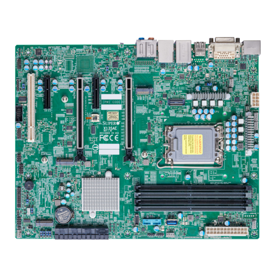
Introduction Congratulations on purchasing your computer motherboard from an industry leader. Supermicro motherboards are designed to provide you with the highest standards in quality and performance. In addition to the motherboard, several important parts that are included in the retail box are listed below. - Page 8 Super X13SAE/X13SAE-F User's Manual Figure 1-1. X13SAE Motherboard Image Note: All graphics shown in this manual were based upon the latest PCB revision avail- able at the time of publication of the manual. The motherboard you received may or may not look exactly the same as the graphics shown in this manual.
- Page 9 Chapter 1: Introduction Figure 1-2. X13SAE-F Motherboard Image Note: All graphics shown in this manual were based upon the latest PCB revision avail- able at the time of publication of the manual. The motherboard you received may or may not look exactly the same as the graphics shown in this manual.
- Page 10 Super X13SAE/X13SAE-F User's Manual Figure 1-3. X13SAE Motherboard Layout (not drawn to scale) AUDIO_FP HDMI AUDIO LAN2 LAN1 USB0/1 USB8/9 (3.2 (10Gb)) USB7 (3.2 (10Gb)) USB10 (3.2 (20Gb)) BMC_HB_LED JPL2 CPU_FAN1 JPL1 JPAC1 JPW2 MAC CODE PCI-E M.2-M3 BMC CODE...
- Page 11 Chapter 1: Introduction Figure 1-4. X13SAE-F Motherboard Layout (not drawn to scale) LED4 AUDIO_FP HDMI AUDIO LAN2 LAN1 IPMI_LAN USB8/9 (3.2 (10Gb)) USB7 (3.2 (10Gb)) USB0/1 USB10 (3.2 (20Gb)) BMC_HB_LED JPL2 CPU_FAN1 JPL1 JPAC1 JPW2 MAC CODE PCI-E M.2-M3 BMC CODE...
- Page 12 Super X13SAE/X13SAE-F User's Manual Quick Reference (X13SAE) LAN2 BMC_HB_LED USB8/9 LAN1 USB7/10 SLOT4 SLOT5 SLOT7 USB0/1 SLOT2 HDMI JPL2 AUDIO PCI-E M.2-M2 AUDIO_FP AUDIO_FP HDMI AUDIO LAN2 LAN1 USB0/1 USB8/9 (3.2 (10Gb)) USB7 (3.2 (10Gb)) JPL1 USB10 (3.2 (20Gb)) BMC_HB_LED...
- Page 13 Chapter 1: Introduction Quick Reference (X13SAE-F) LAN2 IPMI_LAN BMC_HB_LED LED4 USB8/9 USB0/1 LAN1 USB7/10 SLOT4 SLOT5 SLOT7 SLOT2 HDMI JPL2 AUDIO PCI-E M.2-M2 LED4 AUDIO_FP AUDIO_FP HDMI AUDIO LAN2 LAN1 IPMI_LAN USB8/9 (3.2 (10Gb)) USB7 (3.2 (10Gb)) USB0/1 JPL1 USB10 (3.2 (20Gb))
- Page 14 X13SAE-F: Blinking Green (BMC Normal) CATERR_LED Catastrophic Error LED Solid Orange: System CATERR LED4 Unit Identifier (UID) LED (X13SAE-F, IPMI only) Solid Blue: Unit Identified PWR_LED Onboard Power LED Solid Green: Power On Note: The table above is continued on the next page.
- Page 15 Back Panel High Definition Multimedia Interface (2.0b) Digital Video Interface (DVI-D) I-SATA0 - I-SATA7 Intel Serial ATA (SATA 3.0) Ports (6Gb/second) IPMI_LAN Dedicated IPMI LAN Port (X13SAE-F only) Front Control Panel Header Chassis Intrusion Header JLED1 3-pin Power LED Header...
- Page 16 • One HDMI 2.0b connection on the rear I/O panel • One DVI-D port on the rear I/O panel • One VGA port on the rear I/O panel (X13SAE-F only) Note: The table above is continued on the next page.
- Page 17 Note: Please connect a cable from the Chassis Intrusion header at JL1 to the chassis to receive an alert. LED Indicators • BMC_HB_LED • CATERR_LED • Power LED • UID LED (X13SAE-F, IPMI only) Note: The table above is continued on the next page.
- Page 18 Super X13SAE/X13SAE-F User's Manual Motherboard Features Dimensions • 12" (W) x 9.6" (L) ATX (304.8mm x 243.84mm) Note: The CPU maximum thermal design power (TDP) is subject to chassis and heatsink cooling restrictions. For proper thermal management, please check the chassis and heatsink...
- Page 19 Chapter 1: Introduction Figure 1-5. System Block Diagram CPU_PE5*8 PCIe x16 SLOT #7 PCIe Gen5 CPU_PE5*8 Mux/DeMux SVID IMVP9.1 VR PESLOT4_PRSNT_N INTEL LGA1700 PCIe x8 SLOT #4 DDR5 (CHA) DIMMA1 CPU PE4 *4 UP TO 125W M.2 M-KEY*1 DIMMA2 (Gray) 4400Mhz (1DIMM) 4000Mhz (2DPC) Digital port 1(Port A)
-
Page 20: Processor And Chipset Overview
1.2 Processor and Chipset Overview Built upon the functionality and capability of the 12th Gen. Intel Core i9/i7/i5/i3 series processor (LAG1700) and the PCH W680 chipset, the X13SAE/X13SAE-F motherboard provides system performance, power efficiency, and feature sets to address the needs of next-generation computer users. -
Page 21: System Health Monitoring
Chapter 1: Introduction 1.4 System Health Monitoring Onboard Voltage Monitors An onboard voltage monitor will scan the voltages of the onboard chipset, memory, CPU, and battery continuously. Once a voltage becomes unstable, a warning is given, or an error message is sent to the screen. The user can adjust the voltage thresholds to define the sensitivity of the voltage monitor. -
Page 22: Acpi Features
It is even more important for processors that have high CPU clock rates where noisy power transmission is present. The X13SAE/X13SAE-F motherboard accommodates a 24-pin ATX power supply. Although most power supplies generally meet the specifications required by the CPU, some are inadequate. -
Page 23: Serial Header
Chapter 1: Introduction 1.7 Serial Header The X13SAE/X13SAE-F motherboard supports one serial communication connection. The COM header (COM1) can be used for input/output. The UART provides legacy speeds with a baud rate of up to 115.2 Kbps as well as an advanced speed with baud rates of 250 K, 500 K, or 1 Mb/s, which support high-speed serial communication devices. -
Page 24: Chapter 2 Installation
Super X13SAE/X13SAE-F User's Manual Chapter 2 Installation 2.1 Static-Sensitive Devices Electrostatic Discharge (ESD) can damage electronic com ponents. To avoid damaging your system board, it is important to handle them very carefully. The following measures are generally sufficient to protect your equipment from ESD. -
Page 25: Processor And Heatsink Installation
If you buy a CPU separately, make sure that you use an Intel-certified multi-directional heatsink only. • Refer to the Supermicro website for updates on processor support. • All graphics in this manual are for illustrations only. Your components may look different. - Page 26 Super X13SAE/X13SAE-F User's Manual 2. Gently push down the load lever to release and lift it, then lift the load plate to open it completely. Lever lock 3. Use your thumb and your index finger to hold the CPU. Align the small triangle marker and notches on the CPU to the corresponding triangle marker and notches on the CPU load bracket.
- Page 27 Chapter 2: Installation 6. Close the load plate with the CPU inside the socket. Gently push the load lever down until it locks under the Lever Lock latch. Lever lock Attention! You can only install the CPU inside the socket in one direction. Make sure that it is properly inserted into the CPU socket before closing the load plate.
- Page 28 Super X13SAE/X13SAE-F User's Manual Installing a CPU Heatsink Note 1: The installation described in this section is for reference only. The actual in- stallation steps may vary depending on the CPU heatsink model. Please refer to the heatsink instruction for more details.
- Page 29 Chapter 2: Installation 3. Attach the backplate into the mounting holes around the CPU socket on the bottom side of the motherboard. Backplate bottom side Motherboard bottom side Mounting hole Motherboard Top side...
- Page 30 Super X13SAE/X13SAE-F User's Manual 4. Apply the proper amount of thermal grease on the CPU. 5. Place the heatsink on top of the CPU so that the four mounting holes on the heatsink are aligned with those on the retention mechanism.
- Page 31 Chapter 2: Installation Removing a CPU Heatsink Warning: We do not recommend that the CPU or heatsink be removed. However, if you do need to remove the heatsink, please follow the instruction below to uninstall the heatsink to avoid damaging the CPU or other components. 1.
-
Page 32: Motherboard Installation
Super X13SAE/X13SAE-F User's Manual 2.3 Motherboard Installation All motherboards have standard mounting holes to fit different types of chassis. Make sure that the locations of all the mounting holes for both the motherboard and the chassis match. Although a chassis may have both plastic and metal mounting fasteners, metal ones are highly recommended because they ground the motherboard to the chassis. - Page 33 Chapter 2: Installation Installing the Motherboard 1. Install the I/O shield into the back of the chassis, if applicable. 2. Locate the mounting holes on the motherboard. Refer to the previous page for the location. 3. Locate the matching mounting holes on the chassis. Align the mounting holes on the motherboard against the mounting holes on the chassis.
-
Page 34: Memory Support And Installation
Super X13SAE/X13SAE-F User's Manual 2.4 Memory Support and Installation Note: Check the Supermicro website for recommended memory modules. Important: Exercise extreme care when installing or removing DIMM modules to pre- vent any possible damage. General Guidelines for Optimizing Memory Performance •... - Page 35 DIMMA2, DIMMB2, then DIMMA1, DIMMB1. For the system to work properly, use memory BIOS LICENSE modules of the same type and speed. X13SAE-F REV:1.00 DESIGNED IN USA 2. Align the DIMM module key with the receptive point on the single-latch DIMM slot.
-
Page 36: Installation
Super X13SAE/X13SAE-F User's Manual 2.5 M.2 Installation This motherboard has three PCIe 4.0 M.2 M-key 2280 sockets that support the M.2 2280 module. One standoff is pre-installed into the position of 2280 BIOS LICENSE X13SAE-F mounting hole. Refer to the illustration on the right REV:1.00... -
Page 37: Rear I/O Ports
12 USB8: USB 3.2 Gen. 2 (Type-A) VGA Port (X13SAE-F only) 13 USB9: USB 3.2 Gen. 2 (Type-A) Digital Video Interface (DVI-D) 14 Center/LFE Out Dedicated IPMI LAN Port (X13SAE-F only) 15 Surround Out USB0: USB 2.0 (Type-A) 16 S/PDIF Out USB1: USB 2.0 (Type-A) - Page 38 Super X13SAE/X13SAE-F User's Manual Universal Serial Bus (USB) Connections There are two USB 2.0 Type-A ports (USB0, USB1), three USB 3.2 Gen. 2x1 Type-A ports (USB7, USB8, USB9), and one USB 3.2 Gen. 2x2 Type-C port (USB10) are located on the I/O back panel.
- Page 39 Chapter 2: Installation Back Panel High Definition Audio (HD Audio) This motherboard features a 7.1+2 Channel High Definition Audio (HDA) codec that provides 10 DAC channels. The HD Audio connections simultaneously supports multiple-streaming 7.1 sound playback with 2 channels of independent stereo output through the front panel stereo out for front, rear, center, and subwoofer speakers.
- Page 40 DVI-D Port A DVI-D port is located on the I/O back panel. Use this port to connect to a compatible Digital Visual Interface (DVI) display. 1. DisplayPort 1.4a 2. HDMI 2.0b Port 3. VGA Port (X13SAE-F only) 4. DVI-D Port...
- Page 41 IPMI LAN Port (IPMI_LAN) Pin Definitions Pin# Definition Pin# Definition Act LED TD0+ (Yellow) Link 100 LED TD0- (Green) Link 1000 LED TD1+ (Amber) TD1- SGND TD2+ SGND TD2- SGND TD3+ SGND TD3- 1. IPMI LAN Port (X13SAE-F only) 2. LAN1 3. LAN2...
-
Page 42: Front Control Panel
These connectors are designed specifically for use with Supermicro chassis. Refer to the figure below for the descriptions of the front control panel buttons and LED indicators. - Page 43 Pin Definitions (JF1) Pin# Definition Reset Ground 1. Power Button Power Button #1~2 Ground Reset Button 2. Reset Button #3~4 Ground Power Fail LED OH/Fan Fail LED NIC2 LED NIC1 LED Vcc (X13SAE) HDD LED UID SW (X13SAE-F) Power LED Ground...
- Page 44 Super X13SAE/X13SAE-F User's Manual Power Fail LED The Power Fail LED connection is located on pins 5 and 6 of JF1. Refer to the table below for pin definitions. Power Fail LED Pin Definitions (JF1) Pin# Definition 3.3V PWR Supply Fail...
- Page 45 Definition +3.3V Stby Power LED 1. HDD LED/UID Switch Power Button #1~2 Ground Reset Button 2. Power LED #3~4 Ground Power Fail LED OH/Fan Fail LED NIC2 LED NIC1 LED Vcc (X13SAE) HDD LED UID SW (X13SAE-F) Power LED Ground...
-
Page 46: Connectors
Super X13SAE/X13SAE-F User's Manual 2.8 Connectors This section provides brief descriptions and pinout definitions for onboard headers and connectors. Be sure to use the correct cable for each header or connector. Power Connections ATX Power Supply Connector The 24-pin power supply connector (JPW1) meets the ATX SSI EPS 12V specification. You must also connect the 8-pin (JPW2) processor power connector to the power supply. - Page 47 USB10 (3.2 (20Gb)) BMC_HB_LED JPL2 CPU_FAN1 JPL1 JPAC1 JPW2 MAC CODE PCI-E M.2-M3 BMC CODE COM1 BAR CODE CPU_FAN2 BIOS LICENSE CATERR_LED X13SAE-F USB2/3 12V_PUMP_PWR1 REV:1.00 DESIGNED IN USA MAC CODE JTPM1 PCI-E M.2-M2 DIMMA1 DIMMA2 DIMMB1 DIMMB2 JBT1 JPME2 JLED1 USB11 (3.2 (20Gb))
- Page 48 Super X13SAE/X13SAE-F User's Manual Headers Fan Headers There are five 4-pin fan headers (CPU_FAN1, CPU_FAN2, SYS_FAN1 - SYS_FAN3) on the motherboard. Although pins 1-3 of the system fan headers are backwards compatible with the traditional 3-pin fans, the 4-pin fans are recommended to take advantage of the fan speed control.
- Page 49 USB10 (3.2 (20Gb)) BMC_HB_LED JPL2 CPU_FAN1 JPL1 JPAC1 JPW2 MAC CODE PCI-E M.2-M3 BMC CODE COM1 BAR CODE CPU_FAN2 BIOS LICENSE CATERR_LED X13SAE-F USB2/3 12V_PUMP_PWR1 REV:1.00 DESIGNED IN USA MAC CODE JTPM1 PCI-E M.2-M2 DIMMA1 DIMMA2 DIMMB1 DIMMB2 JBT1 JPME2 JLED1 USB11 (3.2 (20Gb))
- Page 50 Super X13SAE/X13SAE-F User's Manual DOM Power Connector The Disk-On-Module (DOM) Power connector, located at JSD1, provides 5V power to a solid state DOM storage device connected to one of the SATA ports. Refer to the table below for pin definitions.
- Page 51 JPL2 3. PCI-E M.2-M3 CPU_FAN1 JPL1 JPAC1 JPW2 MAC CODE PCI-E M.2-M3 BMC CODE COM1 BAR CODE CPU_FAN2 BIOS LICENSE CATERR_LED X13SAE-F USB2/3 12V_PUMP_PWR1 REV:1.00 DESIGNED IN USA MAC CODE JTPM1 PCI-E M.2-M2 DIMMA1 DIMMA2 DIMMB1 DIMMB2 JBT1 JPME2 JLED1 USB11 (3.2 (20Gb))
- Page 52 Super X13SAE/X13SAE-F User's Manual SATA Ports With the Intel W680 PCH chipset, this motherboard has built-in eight Serial ATA (SATA) 3.0 connectors (I-SATA0 - I-SATA07). You can connect up to eight SATA storage devices and create SATA RAID (0, 1, 5, and 10) with up to six SATA storage devices.
- Page 53 USB10 (3.2 (20Gb)) BMC_HB_LED JPL2 CPU_FAN1 JPL1 JPAC1 JPW2 MAC CODE PCI-E M.2-M3 BMC CODE COM1 BAR CODE CPU_FAN2 BIOS LICENSE CATERR_LED X13SAE-F USB2/3 12V_PUMP_PWR1 REV:1.00 DESIGNED IN USA MAC CODE JTPM1 PCI-E M.2-M2 DIMMA1 DIMMA2 DIMMB1 DIMMB2 JBT1 JPME2 JLED1 USB11 (3.2 (20Gb))
- Page 54 Super X13SAE/X13SAE-F User's Manual Serial (COM) Header There is one serial (COM) header on the motherboard. COM1 is located next to expansion SLOT1 (PCI 33MHz). Refer to the table below for pin definitions. Serial (COM) Header Pin Definitions Pin# Definition...
- Page 55 Port 80 connection. Use this header to enhance system performance and data security. Refer to the table below for pin definitions. Please go to the following link for more information on the TPM: http://www.supermicro.com/manuals/other/TPM.pdf. TPM/Port 80 Header Pin Definitions...
-
Page 56: Jumper Settings
Super X13SAE/X13SAE-F User's Manual 2.9 Jumper Settings How Jumpers Work To modify the operation of the motherboard, jumpers can be used to choose between optional settings. Jumpers create shorts between two pins to change the function of the connector. Pin 1 is identified with a square solder pad on the printed circuit board. Refer to the diagram below for an example of jumping pins 1 and 2. - Page 57 USB10 (3.2 (20Gb)) BMC_HB_LED JPL2 CPU_FAN1 JPL1 JPAC1 JPW2 MAC CODE PCI-E M.2-M3 BMC CODE COM1 BAR CODE CPU_FAN2 BIOS LICENSE CATERR_LED X13SAE-F USB2/3 12V_PUMP_PWR1 REV:1.00 DESIGNED IN USA MAC CODE JTPM1 PCI-E M.2-M2 DIMMA1 DIMMA2 DIMMB1 DIMMB2 JBT1 JPME2 JLED1 USB11 (3.2 (20Gb))
- Page 58 Super X13SAE/X13SAE-F User's Manual Manufacturing Mode Close pins 2-3 of JPME2 to bypass SPI flash security and force the system to operate in Manufacturing Mode, allowing you to flash the system firmware from a host server for system setting modifications. Refer to the table below for jumper settings.
- Page 59 Pins 1-2 Enabled (Default) Pins 2-3 Disabled Onboard VGA Enable/Disable (X13SAE-F only) Close pins 1-2 of JPG1 to enable the onboard graphics controller and close pins 2-3 to disable it. Refer to the table below for jumper settings. Onboard VGA Enable/Disable...
-
Page 60: Led Indicators
Yellow 1000Mbps Green 100Mbps 100/10Mbps 10Mbps IPMI LAN LEDs (X13SAE-F only) The IPMI LAN port is located at IPMI_LAN on the I/O back panel. Refer to the table below for more information. IPMI LAN LEDs LED State Color Status Definition... - Page 61 BMC Heartbeat LED (BMC_HB_LED) is located next to the PCIe SLOT5 on the motherboard. The BMC is functioning normally when the BMC_HB_LED is blinking (X13SAE-F only). The standby power is on when the BMC_HB_LED is solid green (X13SAE only). Refer to the table below for more information.
- Page 62 Orange: On System CATERR UID LED (LED4, X13SAE-F only) A rear UID LED indicator (LED4) is located near the UID switch on the back I/O panel. This UID indicator provides easy identification of a system unit that may need service.
-
Page 63: Chapter 3 Troubleshooting
Chapter 3: Troubleshooting Chapter 3 Troubleshooting 3.1 Troubleshooting Procedures Use the following procedures to troubleshoot your system. If you have followed all of the procedures below and still need assistance, refer to the Section 3.2 Technical Support Procedures and/or Section 3.5 Returning Merchandise for Service section(s) in this chapter. - Page 64 Super X13SAE/X13SAE-F User's Manual No Video 1. If the power is on, but you have no video, remove all add-on cards and cables. 2. Use the speaker to determine if any beep codes are present. Refer to Appendix A for details on beep codes.
- Page 65 Chapter 3: Troubleshooting Losing the System's Setup Configuration 1. Make sure that you are using a high-quality power supply. A poor-quality power supply may cause the system to lose the CMOS setup information. Refer to Section 1.6 Power Supply in Chapter 1 for details on recommended power supplies. 2.
-
Page 66: Technical Support Procedures
Before contacting Technical Support, please take the following steps. Also, please note that as a motherboard manufacturer, Supermicro also sells motherboards through its channels, so it is best to first check with your distributor or reseller for troubleshooting services. They should know of any possible problems with the specific system configuration that was sold to you. -
Page 67: Frequently Asked Questions
Note: The SPI BIOS chip used on this motherboard cannot be removed. Send your motherboard back to our RMA Department at Supermicro for repair. For BIOS Recovery instructions, please refer to the AMI BIOS Recovery Instructions posted at http://www. -
Page 68: Battery Removal And Installation
Super X13SAE/X13SAE-F User's Manual 3.4 Battery Removal and Installation Battery Removal To remove the onboard battery, follow the steps below: 1. Power off your system and unplug your power cable. 2. Locate the onboard battery as shown below. 3. Use a tool such as a pen or a small screwdriver, push the battery lock outwards to unlock it. -
Page 69: Returning Merchandise For Service
For faster service, you can also request a RMA authorization online (http://www.supermicro. com/RmaForm/). This warranty only covers normal consumer use and does not cover damages incurred in shipping or from failure due to the alternation, misuse, abuse, or improper maintenance of products. -
Page 70: Chapter 4 Uefi Bios
Super X13SAE/X13SAE-F User's Manual Chapter 4 UEFI BIOS 4.1 Introduction This chapter describes the AMIBIOS™ Setup utility for the motherboard. The BIOS is stored on a chip and can be easily upgraded using a flash program. Note: Due to periodic changes to the BIOS, some settings may have been added or deleted and might not yet be recorded in this manual. -
Page 71: Main
Note: The time is in the 24-hour format. For example, 5:30 P.M. appears as 17:30:00. The date's default value is the BIOS build date after RTC reset. Supermicro X13SAE-F BIOS Version This item displays the version of the BIOS ROM used in the system. - Page 72 Super X13SAE/X13SAE-F User's Manual Memory Information Total Memory This feature displays the total size of memory available in the system.
-
Page 73: Advanced
Chapter 4: UEFI BIOS 4.3 Advanced Use the arrow keys to select the Advanced menu and press <Enter> to access the submenu items: Warning: Take caution when changing the Advanced settings. An incorrect value, a very high DRAM frequency, or an incorrect DRAM timing setting may make the system unstable. When this occurs, revert to default manufacturer settings. - Page 74 Super X13SAE/X13SAE-F User's Manual High Precision Event Timer Select Enabled to activate the High Precision Event Timer (HPET) that produces periodic interrupts at a much higher frequency than a Real-time Clock (RTC) does in synchronizing multimedia streams, providing smooth playback and reducing the dependency on other timestamp calculation devices, such as an x86 RDTSC Instruction embedded in the CPU.
- Page 75 Chapter 4: UEFI BIOS Power Configuration Watch Dog Function If this feature is enabled, the Watch Dog Timer will allow the system to reset or generate NMI based on jumper settings when it is expired for more than five minutes. The options are Disabled and Enabled.
- Page 76 Super X13SAE/X13SAE-F User's Manual • SMX/TXT • 64-bit • EIST Technology • CPU C3 state • CPU C6 state • CPU C7 state • CPU C8 state • CPU C9 state • CPU C10 state • Performance L1 Data Cache •...
- Page 77 Chapter 4: UEFI BIOS Intel (VMX) Virtualization Technology Select Enable to use Intel Virtualization Technology so that I/O device assignments will be reported directly to the VMM (Virtual Memory Management) through the DMAR ACPI Tables. This feature offers fully-protected I/O resource-sharing across the Intel platforms, providing you with greater reliability, security and availability in networking and data-sharing.
- Page 78 Super X13SAE/X13SAE-F User's Manual Power Limit 1 Override Select Enabled to support average power limit (PL1) override. The options are Disabled and Enabled. Power Limit 2 Override Select Enabled to support rapid power limit (PL2) override. The options are Disabled and Enabled.
- Page 79 Chapter 4: UEFI BIOS Package C-State Limit Use this feature to set the Package C-State limit. The options are C0/C1, C2, C3, C6, C7, C7S, C8, C9, C10, CPU Default, and AUTO. MonitorMWait Select Enabled to activate MonitorMWait. The options are Disabled and Enabled. Chipset Configuration Warning: Setting the wrong values in the following features may cause the system to malfunction.
- Page 80 Super X13SAE/X13SAE-F User's Manual Max TOLUD (Top of Low Usable DRAM) This feature sets the maximum TOLUD value, which specifies the "Top of Low Usable DRAM" memory space to be used by internal graphics devices, GTT Stolen Memory, and TSEG, respectively, if these devices are enabled. The options are Dynamic, 1 GB, 1.25 GB, 1.5 GB, 1.75 GB, 2 GB, 2.25 GB, 2.5 GB, 2.75 GB, 3 GB, 3.25 GB,...
- Page 81 Chapter 4: UEFI BIOS Graphics Configuration Graphics Configuration The following graphic information will be displayed: • IGFX GOP Version Graphics Turbo IMON Current Enter a value for the graphics turbo IMON current. The range is 14-31. The default is 31. Note: This feature becomes configurable if the installed CPU has a built-in integrated graphics function.
- Page 82 Super X13SAE/X13SAE-F User's Manual DVMT Total Gfx Mem This feature controls the DVMT 5.0 total graphics size to be used by the internal graph- ics device. The options are 128M, 256M, and MAX. PM Support This feature enables PM support. The options are Enabled and Disabled.
- Page 83 Chapter 4: UEFI BIOS Max Link Speed Use this feature to select the PCI Express port speed. The options are Auto, Gen1, Gen2, Gen3, and Gen4. CPU SLOT7 PCI-E 5.0 X16 Enable Root Port Select Enable to activate the Root Port. The options are Disabled and Enabled. Max Link Speed Use this feature to select the PCI Express port speed.
- Page 84 Super X13SAE/X13SAE-F User's Manual VT-d Select Enabled to enable Intel Virtualization Technology support for Direct I/O VT-d by reporting the I/O device assignments to VMM through the DMAR ACPI Tables. This feature offers fully-protected I/O resource-sharing across the Intel platforms, providing you with greater reliability, security and availability in networking and data sharing.
- Page 85 Chapter 4: UEFI BIOS L1 Substates Use this feature to configure the PCI Express L1 Substates. The options are Dis- abled, L1.1, and L1.1 & L1.2. PCIe Speed Use this feature to select the PCI Express port speed. The options are Auto, Gen1, Gen2, Gen3, and Gen4.
- Page 86 Risk!!). Warning: Disabling this option is a violation of RFC 6125 and may expose you to Man-in- the-Middle Attacks. Supermicro computer, Inc. is not responsible for any and all security risks incurred by you disabling this option. Priority of HTTP Boot Instance of Priority 1 / Instance of Priority 2 Use this feature to rank the targeted port.
- Page 87 Chapter 4: UEFI BIOS NCT6796DE Super IO Configuration NCT6796DE Super IO Configuration • Super IO Chip - NCT6796DE Serial Port 1 Configuration Serial Port 1 Configuration Serial Port 1 This feature will Enable or Disable Serial Port (COM1). Check the box to enable Serial Port.
- Page 88 Super X13SAE/X13SAE-F User's Manual PXE boot wait time Enter a value for the wait time (in seconds) to press the <ESC> key to abort the PXE boot. The default is 0. Media detect count Enter a value for the number of times the presence of media will be checked. The default is 1.
- Page 89 Chapter 4: UEFI BIOS • Host addresses • Route Table • Gateway addresses • DNS addresses Interface ID Enter an ID for the device DAD Transmit Count Enter a value for Duplicate Address Detection (DAD) Transmit Count. A value of zero indicates the DAD is not performed.
- Page 90 Super X13SAE/X13SAE-F User's Manual PCH-FW Configuration The following PCH-IO information is displayed: • ME Firmware Version • ME Firmware Mode • ME Firmware SKU ME FW Image Re-Flash Use this feature to enable or disable the ME Firmware image reflash capability. The options are Disabled and Enabled.
- Page 91 Chapter 4: UEFI BIOS WatchDog This feature enables the WatchDog Timer. The options are Disabled and Enabled. *If this feature is set to Enabled, the following features will become available for configuration: OS Timer Enter a value for OS Timer. The default is 0. BIOS Timer Enter a value for BIOS Timer.
- Page 92 Super X13SAE/X13SAE-F User's Manual OCR Disable Secure Boot This feature allows CSME to request SecureBoot to be disabled for One Click Recovery. The options are Disabled and Enabled. PCIe/PCI/Pnp Configuration Option ROM execution Video This feature controls which option ROM to execute for the Video device. The options are Do Not Launch and EFI.
- Page 93 Chapter 4: UEFI BIOS PCIe/PCI/PnP Configuration SLOT1 PCI 33MHz OPROM PCH SLOT2 PCI-E 3.0 X4 OPROM PCH SLOT4 PCI-E 5.0 X8 (IN x16) OPROM CPU SLOT5 PCI-E 3.0 X4 OPROM CPU SLOT7 PCI-E 5.0 X16 OPROM PCI-E M.2-M1 OPROM PCI-E M.2-M2 OPROM PCI-E M.2-M3 OPROM Onboard LAN1 Option ROM Select Disabled to deactivate the selected slot or EFI to activate the slot in UEFI mode.
- Page 94 Super X13SAE/X13SAE-F User's Manual Spin Up Device When this feature is disabled, all drives will spin up at boot. When this option is enabled, it will perform Staggered Spin Up on any drive this option is activated. The options are Disabled and Enabled.
- Page 95 Chapter 4: UEFI BIOS * If the feature above is set to Enabled, the following features will become available for configuration: COM1 Console Redirection Settings / SOL Console Redirection Settings / AMT SOL Console Redirection Settings Use this feature to specify how the host computer will exchange data with the client computer, which is the remote computer used by you.
- Page 96 Super X13SAE/X13SAE-F User's Manual Flow Control Use this feature to set the flow control for Console Redirection to prevent data loss caused by buffer overflow. Send a "Stop" signal to stop sending data when the receiving buffer is full. Send a "Start" signal to start sending data when the receiving buffer is empty. The options are None and Hardware RTS/CTS.
- Page 97 Chapter 4: UEFI BIOS *If the feature above is set to Enabled, the following features will become available for configuration: Console Redirection Settings Out-of-Band Mgmt Port This feature selects a serial port in a client server to be used by the Microsoft Windows Emergency Management Services (EMS) to communicate with a remote host server.
- Page 98 Super X13SAE/X13SAE-F User's Manual • USB Controllers • USB Devices Legacy USB Support Select Enabled to support onboard legacy USB devices. Select Auto to disable legacy support if there are no legacy USB devices connected. Select Disable to have all USB devices available for EFI applications only.
- Page 99 Chapter 4: UEFI BIOS Intel(R) Ethernet Connection (17) I219-LM - XX:XX:XX:XX:XX:XX PORT CONFIGURATION INFORMATION Information for the LAN port configuration is displayed. Note that the items listed below may vary depending on the motherboard. • UEFI Driver • Adapter PBA •...
- Page 100 Super X13SAE/X13SAE-F User's Manual Client Certification Configuration Enroll Certification Enroll Certification Using File Use this feature to enroll certification from a file Certification GUID Use this feature to input the certification Global Unique Identifier (GUID). Commit Changes and Exit Use this feature to save all changes and exit TLS settings.
-
Page 101: Event Logs
Chapter 4: UEFI BIOS 4.4 Event Logs Use this feature to configure Event Log settings. Change SMBIOS Event Log Settings Enabling/Disabling Options SMBIOS Event Log Change this feature to enable or disable all features of the SMBIOS Event Logging during system boot. - Page 102 Super X13SAE/X13SAE-F User's Manual SMBIOS Event Log Standard Settings Log System Boot Event This option toggles the System Boot Event logging to enabled or disabled. The options are Enabled and Disabled. MECI The Multiple Event Count Increment (MECI) counter counts the number of occurrences that a duplicate event must happen before the MECI counter is incremented.
-
Page 103: Thermal & Fan
Chapter 4: UEFI BIOS 4.5 Thermal & Fan Note: This feature is supported by X13SAE only. Use this feature to configure Event Log settings. System Temperature Information for the following is displayed: • CPU Temperature • System Temperature • Peripheral Temperature •... - Page 104 Super X13SAE/X13SAE-F User's Manual System Health Information for the following is displayed: • VCC12 • VCC5 • P_VDD2 • V1P05A_CPU • V1P8A • P_VCCIN_AUX_CPU • VCC3_3_DL • VCC3_3 • VBAT • P_VCCCORE • VCC3_ALW Fan Control Fan Control Setting Fan Speed Control Mode Use this feature to set the fan speed control mode.
-
Page 105: Ipmi (X13Sae-F Only)
Use this feature to configure Intelligent Platform Management Interface (IPMI) settings. Notes: 1. This feature is supported by X13SAE-F only. 2. When changing a setting in this section, be sure to reboot the system for the changes to take effect. - Page 106 Super X13SAE/X13SAE-F User's Manual *If the feature above is set to Enabled, the following features will become available for configuration: Erasing Settings Erase SEL Select Yes, On next reset to erase all system event logs upon next system reboot. Select Yes, On every reset to erase all system event logs upon each system reboot.
- Page 107 Chapter 4: UEFI BIOS *If the Configuration Address Source is set to DHCP, the following features will be displayed: • Station IP Address • Subnet Mask • Station MAC Address • Gateway IP Address *If the Configuration Address Source is set to Static, the following features will become available for configuration: Station IP Address This feature displays the Station IP address for this computer.
- Page 108 Super X13SAE/X13SAE-F User's Manual *If the feature above is set to Enabled, the following feature will become available for configuration: Configuration Address Source This feature allows you to select the source of the IP address for this computer. If Static is selected, you will need to know the IP address of this computer and enter it to the system manually in the field.
-
Page 109: Security
Chapter 4: UEFI BIOS 4.7 Security This menu allows you to configure the following security settings for the system. Administrator Password Press <Enter> to create a new or change an existing administrator password. *If the password has been created, the feature of User Password below will become available for configuration. - Page 110 Super X13SAE/X13SAE-F User's Manual Security Function Use this feature to set Security Function. The options are Disabled, Security Erase, and Set Password. Password Enter a numeric value to set the password. Hard Drive Security Frozen Use this feature to disable or enable the BIOS security frozen command to SATA and NVMe devices.
- Page 111 Chapter 4: UEFI BIOS Enter Deployed Mode Press <Enter> button to transition between Deployment and User Mode Exit Deployed Mode Press <Enter> button to switch between Deployment and User Mode. Key Management Restore Factory Keys This feature resets the content of all UEFI Secure Boot key databases to factory defaults. Reset to Setup Mode This feature deletes the contents of all UEFI Secure Boot key databases.
- Page 112 Super X13SAE/X13SAE-F User's Manual Update Select Yes to load the KEK from the manufacturer's defaults. Select No to load the KEK from a file. Append Select Yes to add the KEK from the manufacturer's defaults list to the existing KEK.
- Page 113 Chapter 4: UEFI BIOS Append Select Yes to add the DBX from the manufacturer's defaults to the existing DBX. Select No to load the DBX from a file. Delete Select Yes to delete the Forbidden Signatures key database. Select No to delete only a certificate from the key database.
- Page 114 Super X13SAE/X13SAE-F User's Manual Append Select Yes to add the DBT from the manufacturer's defaults list to the existing DBT. Select No to load the DBT from a file. Delete Select Yes to delete the OsRecovery Signatures key database. Select No to delete only a certificate from the key database.
-
Page 115: Boot
Chapter 4: UEFI BIOS 4.8 Boot Use this feature to configure Boot Settings: Fixed Boot order Priorities This feature prioritizes the order of a bootable device from which the system will boot. Press <Enter> on each item sequentially to select devices. UEFI Boot Option #1~#9 The options are UEFI Hard Disk, UEFI CD/DVD, UEFI USB Hard Disk, UEFI USB CD/DVD, USB Key, UEFI USB Floppy, UEFI USB Lan, UEFI Network, UEFI AP, and Disabled. - Page 116 Super X13SAE/X13SAE-F User's Manual UEFI NETWORK Drive BBS Priorities / UEFI Application Boot Priorities Note: These submenus are subject to change depending on the devices installed on this motherboard. Boot Option #1~X Use this feature to set the system boot order. The number of X is depending on the devices...
-
Page 117: Save & Exit
Chapter 4: UEFI BIOS 4.9 Save & Exit Use this feature to save the configurations or leave the BIOS Setup utility. Save Options Discard Changes and Exit Select this feature to leave the BIOS Setup utility without making any permanent changes to the system configuration, and reboot the computer. - Page 118 Super X13SAE/X13SAE-F User's Manual Default Options Load Optimized Defaults Select this feature and press <Enter> to load the optimized defaults. These are factory settings designed for maximum system stability, but not for maximum performance. Save As User Defaults Select this feature and press <Enter> to save as the user defaults. This enables you to save any changes to the BIOS setup for future use.
-
Page 119: Mebx
Chapter 4: UEFI BIOS 4.10 MEBx Use this feature to configure the MEBx. Intel(R) ME Password Enter the password to bring up the Intel Management Engine (ME) setting menu. By default, the password is "admin" if you are the first time login. Intel ME will then prompt you to generate a new password. - Page 120 Super X13SAE/X13SAE-F User's Manual *If the feature above is set to Enabled, the following features will become available for configuration: Intel(R) AMT Configuration Redirection feature Note: The features listed here are only for enabling the capability. To execute these features, you still need other tools like Intel AMT SDK.
- Page 121 Chapter 4: UEFI BIOS Password Policy Use this feature to set the password policy. The options are Default Password Only, During Setup and Configuration, and Anytime. • Default Password: If the default password has not been changed yet, the Intel MEBx password can be changed via the network interface.
- Page 122 Super X13SAE/X13SAE-F User's Manual TCP/IP Settings Wired LAN IPV4 Configuration DHCP Mode This feature allows the Intel ME to configure its network settings via the Dynamic Host and Configuration Protocol (DHCP) server in the network. The options are Disabled and Enabled.
- Page 123 Chapter 4: UEFI BIOS • FQDN • Serial Number • Time Validity Pass Note: If the feature shows "Provision Record is not present", it means there is no data entered. Provisioning Server address Press <Enter> to set the provisioning server address. It could be either host name, IPv4, or IPv6 address.
- Page 124 Super X13SAE/X13SAE-F User's Manual Idle Timeout Use this feature to set a timeout value in minutes. The default is 65535. Intel(R) OEM Debug Configuration Idle time based M3 to Moff entry OVERRIDE Use this feature to enable or disable the Idle time based M3 to Moff entry OVERRIDE.
-
Page 125: Appendix A Bios Codes
Appendix A: BIOS Codes Appendix A BIOS Codes A.1 BIOS Error POST (Beep) Codes During the Power-On Self-Test (POST) routines, which are performed each time the system is powered on, errors may occur. Non-fatal errors are those which, in most cases, allow the system to continue the boot up process. -
Page 126: Additional Bios Post Codes
When BIOS performs the Power On Self Test, it writes checkpoint codes to I/O port 0080h. If the computer cannot complete the boot process, a diagnostic card can be attached to the computer to read I/O port 0080h (Supermicro p/n AOC-LPC80-20). For information on AMI updates, please refer to http://www.ami.com/products/. -
Page 127: Appendix B Software
USB/SATA DVD drive, or a USB flash drive, or the IPMI KVM console. 2. Retrieve the proper RST/RSTe driver. Go to the Supermicro web page for your motherboard and click on "Download the Latest Drivers and Utilities", select the proper driver, and copy it to a USB flash drive. - Page 128 Super X13SAE/X13SAE-F User's Manual 4. During Windows Setup, continue to the dialog where you select the drives on which to install Windows. If the disk you want to use is not listed, click on “Load driver” link at the bottom left corner.
-
Page 129: Driver Installation
Appendix B: Software B.2 Driver Installation The Supermicro website that contains drivers and utilities for your system is at https://www. supermicro.com/wdl/driver/. Some of these must be installed, such as the chipset driver. After accessing the website, go into the CDR_Images (in the parent directory of the above link) and locate the ISO file for your motherboard. -
Page 130: Superdoctor 5
Super X13SAE/X13SAE-F User's Manual B.3 SuperDoctor 5 The Supermicro SuperDoctor 5 is a program that functions in a command-line or web-based interface for Windows and Linux operating systems. The program monitors such system health information as CPU temperature, system voltages, system power consumption, fan speed, and provides alerts via email or Simple Network Management Protocol (SNMP). -
Page 131: Ipmi (X13Sae-F Only)
When logging in to the BMC for the first time, please use the unique password provided by Supermicro to log in. You can change the unique password to a user name and password of your choice for subsequent logins. -
Page 132: Appendix C Standardized Warning Statements
The following statements are industry standard warnings, provided to warn the user of situations which have the potential for bodily injury. Should you have questions or experience difficulty, contact Supermicro's Technical Support department for assistance. Only certified technicians should attempt to install or configure components. - Page 133 Appendix C: Standardized Warning Statements Attention Danger d'explosion si la pile n'est pas remplacée correctement. Ne la remplacer que par une pile de type semblable ou équivalent, recommandée par le fabricant. Jeter les piles usagées conformément aux instructions du fabricant. ¡Advertencia! Existe peligro de explosión si la batería se reemplaza de manera incorrecta.
- Page 134 Super X13SAE/X13SAE-F User's Manual Product Disposal Warning! Ultimate disposal of this product should be handled according to all na- tional laws and regulations. 製品の廃棄 この製品を廃棄処分する場合、 国の関係する全ての法律 ・ 条例に従い処理する必要があります。 警告 本产品的废弃处理应根据所有国家的法律和规章进行。 警告 本產品的廢棄處理應根據所有國家的法律和規章進行。 Warnung Die Entsorgung dieses Produkts sollte gemäß allen Bestimmungen und Gesetzen des Landes erfolgen.
-
Page 135: Appendix D Uefi Bios Recovery
Warning: Do not upgrade the BIOS unless your system has a BIOS-related issue. Flashing the wrong BIOS can cause irreparable damage to the system. In no event shall Supermicro be liable for direct, indirect, special, incidental, or consequential damages arising from a BIOS update. -
Page 136: Recovering The Main Bios Block With A Usb Device
1. Please use a different machine to download the BIOS package for your motherboard or your system from the product page available on our website at www.supermicro.com. 2. Extract the BIOS package to a USB device and rename the BIOS ROM file [BIOSname#.###] that is included in the BIOS package to SUPER.ROM for BIOS... - Page 137 Appendix D: UEFI BIOS Recovery 5. After locating the SUPER.ROM file, the system will enter the BIOS Recovery menu as shown below. Note: At this point, you may decide if you want to start the BIOS recovery. If you decide to proceed with BIOS recovery, follow the procedures below.
- Page 138 Super X13SAE/X13SAE-F User's Manual 7. After the BIOS recovery process is complete, press any key to reboot the system. Note: It is recommended that you update your BIOS after BIOS recovery. Please refer to Chapter 3 for BIOS update instructions.
- Page 139 Appendix D: UEFI BIOS Recovery 9. When the UEFI Shell prompt appears, type fs# to change the device directory path. Go to the directory that contains the BIOS package you extracted earlier from Step 2. Enter flash.nsh BIOSname#.### at the prompt to start the BIOS update process. Note: Do not interrupt this process until the BIOS flashing is complete.