Emerson Rosemount 2051 Reference Manual
Pressure transmitter with hart revision 5 and 7 selectable protocol
Hide thumbs
Also See for Rosemount 2051:
- Reference manual (228 pages) ,
- Quick start manual (34 pages) ,
- Quick installation manual (25 pages)

Related Manuals for Emerson Rosemount 2051


Summary of Contents for Emerson Rosemount 2051
- Page 1 Reference Manual 00809-0100-4107, Rev CB September 2020 ™ Rosemount 2051 Pressure Transmitter ® with HART Revision 5 and 7 Selectable Protocol...
- Page 2 Do not attempt to loosen or remove flange bolts while the transmitter is in service. Replacement equipment or spare parts not approved by Emerson or use as spare parts could reduce the pressure retaining capabilities of the transmitter and may render the instrument dangerous.
- Page 3 Severe changes in the electrical loop may inhibit HART Communication or the ability to reach alarm values. Therefore, Emerson cannot absolutely warrant or guarantee that the correct failure alarm level (HIGH or LOW) can be read by the host system at the time of annunciation.
-
Page 5: Table Of Contents
Reference Manual Contents 00809-0100-4107 September 2020 Contents Chapter 1 Introduction......................7 1.1 Using this manual........................7 1.2 Models covered........................... 7 1.3 HART installation flowchart......................8 1.4 Transmitter overview........................9 1.5 Product recycling/disposal......................10 Chapter 2 Configuration......................11 2.1 Overview........................... 11 2.2 Safety messages........................11 2.3 System readiness........................ - Page 6 B.1 Field Communicator menu trees....................115 B.2 Field communicator Fast Keys....................119 Appendix C Local Operator Interface (LOI) Menu............... 121 C.1 LOI menu tree..........................121 C.2 LOI menu tree - extended menu....................122 C.3 Number entry.......................... 123 C.4 Text entry..........................124 Rosemount 2051 Pressure Transmitter...
-
Page 7: Chapter 1 Introduction
September 2020 Introduction Using this manual The sections in this manual provides information on configuring, troubleshooting, operating, and maintaining the Rosemount 2051 Pressure Transmitter specifically with ® HART Revision 5 and 7 Selectable Protocol. The sections in this manual are organized as follows: •... -
Page 8: Hart Installation Flowchart
Introduction Reference Manual September 2020 00809-0100-4107 Note For Rosemount 2051 with FOUNDATION Fieldbus, see Reference Manual. For Rosemount 2051 with PROFIBUS PA Protocol, see Reference Manual. HART installation flowchart Figure 1-1: HART Installation Flowchart Rosemount 2051 Pressure Transmitter... -
Page 9: Transmitter Overview
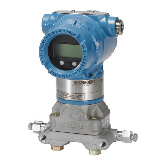
Reference Manual Introduction 00809-0100-4107 September 2020 Transmitter overview ™ The Rosemount 2051C Coplanar design is offered for Differential Pressure (DP) and Gauge Pressure (GP) measurements. The Rosemount 2051C utilizes capacitance sensor technology for DP and GP measurements. The Rosemount 2051T utilizes piezoresistive sensor technology for AP and GP measurements. -
Page 10: Product Recycling/Disposal
A. Sensor Module B. Electronics Board C. 4-20 mA Signal to Control System D. Field Communicator Product recycling/disposal Recycling of equipment and packaging should be taken into consideration and disposed of in accordance with local and national legislation/regulations. Rosemount 2051 Pressure Transmitter... -
Page 11: Chapter 2 Configuration
Reference Manual Configuration 00809-0100-4107 September 2020 Configuration Overview This section contains information on commissioning and tasks that should be performed on the bench prior to installation, as well as tasks performed after installation as described Performing transmitter tests. Field Communicator, AMS Device Manager, and Local Operator Interface (LOI) instructions are given to perform configuration functions. -
Page 12: System Readiness
September 2020 00809-0100-4107 WARNING Replacement equipment or spare parts not approved by Emerson for use as spare parts could reduce the pressure retaining capabilities of the transmitter and may render the instrument dangerous. Use only bolts supplied or sold by Emerson as spare parts. -
Page 13: Configuration Basics
Reference Manual Configuration 00809-0100-4107 September 2020 Example Table 2-1: Rosemount 2051 Device Revisions and Files Software Identify device Find Device Driver Review Review release instructions functionality date NAMUR HART HART Device Reference Changes to software software universal revision manual software... - Page 14 DD’s are loaded into the Field Communicator. Visit Emerson.com FieldCommGroup.org to download latest DD library. Field Communicator menu trees and Fast Keys are available in Field Communicator Menu Trees and Fast Keys. Rosemount 2051 Pressure Transmitter...
- Page 15 Configuring with AMS Device Manager Full configuration capability with AMS Device Manager requires loading the most current Device Descriptor (DD) for this device. Download the latest DD at Emerson.com FieldCommGroup.org. Note All steps using AMS Device Manager will be described using version 11.5.
-
Page 16: Verify Configuration
It is recommended that various configuration parameters are verified prior to installation into the process. The various parameters are detailed out for each configuration tool. Depending on what configuration tool(s) are available follow the steps listed relevant to each tool. Rosemount 2051 Pressure Transmitter... - Page 17 Fast key sequences for the latest DD are shown in Table 2-3. For Fast Key sequences for legacy DD's contact your local Emerson Representative. Table 2-3: Device Dashboard Fast Key sequence From the HOME screen, enter the Fast Key sequences listed...
-
Page 18: Basic Setup Of The Transmitter
Setting pressure units with a LOI Follow Figure 2-5 to select desired pressure and temperature units. Use the SCROLL and ENTER buttons to select desired unit. Save by selecting SAVE as indicated on the LCD display screen. Rosemount 2051 Pressure Transmitter... - Page 19 Reference Manual Configuration 00809-0100-4107 September 2020 Figure 2-5: Selecting Units with LOI UNITS PRESS UNITS VIEW CONFIG PRESS UNITS INH2O ZERO TRIM TEMP UNITS MMHG UNITS BACK TO MENU CMHG0C RERANGE EXIT MENU MHG0C LOOP TEST DISPLAY EXTENDED MENU EXIT MENU TORR 2.6.2 Setting transmitter output (transfer function)
- Page 20 Select from one of the methods below to rerange the transmitter. Each method is unique; examine all options closely before deciding which method works best for your process. • Rerange by manually setting range points with a Field Communicator, AMS Device Manager, or LOI. Rosemount 2051 Pressure Transmitter...
- Page 21 Reference Manual Configuration 00809-0100-4107 September 2020 • Rerange with a pressure input source and a Field Communicator, AMS Device Manager, LOI, or local zero and span buttons. Manually rerange the transmitter by entering range points Entering range points with a Field Communicator From the HOME screen, enter the Fast Key sequence.
- Page 22 To change the span (20 mA/5 V point) while maintaining the zero point: press and hold the span button for at least two seconds and then release. Example Note 4 mA and 20 mA points must maintain the minimum span. Rosemount 2051 Pressure Transmitter...
- Page 23 Reference Manual Configuration 00809-0100-4107 September 2020 Figure 2-10: Analog Zero and Span Buttons A. Zero and span buttons Note • If the transmitter security is on, adjustments to the zero and span will not be able to be made. Refer to Configure security and simulation for security information.
-
Page 24: Configuring The Lcd Display
Configuring the LCD display with LOI for image of LCD display screen. 2.7.1 Configuring LCD display with a Field Communicator From the HOME screen, enter the Fast Key sequence. Device Dashboard Fast Keys 2, 2, 4 Rosemount 2051 Pressure Transmitter... -
Page 25: Detailed Transmitter Setup
Reference Manual Configuration 00809-0100-4107 September 2020 2.7.2 Configuring LCD display with AMS Device Manager Procedure 1. Right select on the device and select Configure. 2. Select Manual Setup, select the Display tab. 3. Select desired display options and click Send. 2.7.3 Configuring LCD display with a LOI Refer to... - Page 26 2. Select Configure Alarm and Saturation Levels button. 3. Follow screen prompts to configure Alarm and Saturation Levels. Configuring alarm and saturation levels using LOI Refer to Figure 2-13 for instructions to configure alarm and saturation levels. Rosemount 2051 Pressure Transmitter...
- Page 27 Reference Manual Configuration 00809-0100-4107 September 2020 Figure 2-13: Configuring Alarm and Saturation with LOI EXTENDED MENU VIEW CONFIG CALIBRAT ZERO TRIM DAMPING UNITS TRANSFER FUNCT RERANGE SCALED VARIAB LOOP TEST ASSIGN PV DISPLAY ALARM SAT VALUES EXTENDED MENU ALARM SAT VALUES ROSEMOUNT VALUES EXIT MENU PASSWORD...
- Page 28 SCALED VARIAB TRANSFER FUNCT RERANGE VIEW SCALED SCALED VARIAB LOOP TEST CONFIG SCALED ASSIGN PV DISPLAY BACK TO MENU EXTENDED MENU EXIT MENU ALARM SAT VALUES EXIT MENU PASSWORD SIMLATE HART REV BACK TO MENU EXIT MENU Rosemount 2051 Pressure Transmitter...
- Page 29 Reference Manual Configuration 00809-0100-4107 September 2020 DP level example Figure 2-15: Example Tank 230- i n. 0. 94 sg 200- i n. 12- i n. A differential transmitter is used in a level application. Once installed on an empty tank and taps vented, the process variable reading is –209.4 inH O.
- Page 30 4. Select Send. 5. Carefully read the warning and select Yes if it is safe to apply the changes. Re-mapping using LOI Refer to Figure 2-16 for instructions to remap the primary variable using a LOI. Rosemount 2051 Pressure Transmitter...
-
Page 31: Performing Transmitter Tests
Reference Manual Configuration 00809-0100-4107 September 2020 Figure 2-16: Re-mapping with LOI VIEW CONFIG EXTENDED MENU ZERO TRIM CALIBRAT UNITS DAMPING RERANGE TRANSFER FUNCT LOOP TEST SCALED VARIAB DISPLAY ASSIGN PV EXTENDED MENU EXIT MENU ALARM SAT VALUES PASSWORD SIMULATE HART REV BACK TO MENU EXIT MENU Performing transmitter tests... - Page 32 Device Dashboard Fast Keys 3, 5 Simulate digital signal with AMS Device Manager Procedure 1. Right select on the device and select Service Tools. 2. Select Simulate. 3. Under Device Variables select a digital value to simulate. a) Pressure Rosemount 2051 Pressure Transmitter...
-
Page 33: Configuring Burst Mode
Reference Manual Configuration 00809-0100-4107 September 2020 b) Sensor Temperature c) Scaled Variable 4. Follow the screen prompts to simulate selected digital value. 2.10 Configuring burst mode ® Burst mode is compatible with the analog signal. Because the HART protocol features simultaneous digital and analog data transmission, the analog value can drive other equipment in the loop while the control system is receiving the digital information. -
Page 34: Establishing Multidrop Communication
Device Manager can test, configure, and format a multidropped transmitter the same way as a transmitter in a standard point-to-point installation. Figure 2-18 shows a typical multidrop network. This figure is not intended as an installation diagram. Rosemount 2051 Pressure Transmitter... - Page 35 Reference Manual Configuration 00809-0100-4107 September 2020 Figure 2-18: Typical Multidrop Network (4–20 mA only) A. HART modem B. Power supply The product is set to address zero (0) at the factory, which allows operation in the standard point-to-point manner with a 4–20 mA (1–5 Vdc) output signal. To activate multidrop communication, the transmitter address must be changed to a number from 1 to 15 for HART Revision 5, or 1–63 for HART Revision 7.
- Page 36 1. Select Utility and Configure HART Application. 2. Select Polling Addresses. 3. Enter 0–63. Communicating with a multidropped transmitter using AMS Device Manager Procedure ® modem icon and select Scan All Devices. Select on the HART Rosemount 2051 Pressure Transmitter...
-
Page 37: Chapter 3 Hardware Installation
00809-0100-4107 September 2020 Hardware Installation Overview The information in this section covers installation considerations for the Rosemount 2051 ® with HART protocols. A Quick Installation Guide is shipped with every transmitter to describe recommended pipe-fitting and wiring procedures for initial installation. -
Page 38: Considerations
September 2020 00809-0100-4107 WARNING Replacement equipment or spare parts not approved by Emerson for use as spare parts could reduce the pressure retaining capabilities of the transmitter and may render the instrument dangerous. Use only bolts supplied or sold by Emerson as spare parts. -
Page 39: Installation Procedures
Reference Manual Hardware Installation 00809-0100-4107 September 2020 3.3.3 Mechanical considerations Steam service For steam service or for applications with process temperatures greater than the limits of the transmitter, do not blow down impulse piping through the transmitter. Flush lines with the blocking valves closed and refill lines with water before resuming measurement. Side mounted When the transmitter is mounted on its side, position the coplanar flange to ensure proper venting or draining. - Page 40 Bolts supplied by Emerson are identified by their head markings. Bolt installation Only use bolts supplied with the transmitter or sold by Emerson as spare parts. The use of non approved bolts could reduce pressure. Use the following bolt installation procedure:...
- Page 41 Reference Manual Hardware Installation 00809-0100-4107 September 2020 Figure 3-2: Traditional Flange Bolt Configurations A. Differential transmitter B. Gauge/Absolute transmitter C. Drain/vent D. Plug E. 1.75 (44) × 4 F. 1.50 (38) × 4 Note: Dimensions are in inches (millimeters) Figure 3-3: Mounting Bolts and Bolt Configurations for Coplanar Flange A.
- Page 42 Rosemount 2051T Transmitters are direct mount and do not require bolts for process connection. Figure 3-4: Mounting Bracket Option Codes B1, B7, and BA A. 3.75 (95) B. 1.63 (41) C. 4.09 (104) D. 2.73 (69) E. 4.97 (126) F. 2.81 (71) Rosemount 2051 Pressure Transmitter...
- Page 43 Reference Manual Hardware Installation 00809-0100-4107 September 2020 Figure 3-5: Panel Mounting Bracket Option Codes B2 and B8 A. 3.75 (95) A. 1.40 (36) B. 1.63 (41) B. Mounting holes 0.375 diameter (10) C. 4.09 (104) C. 1.405 (35,7) D. 2.81 (71) D.
- Page 44 Hardware Installation Reference Manual September 2020 00809-0100-4107 Mounting brackets Rosemount 2051 transmitters may be panel-mounted or pipe-mounted via an optional mounting bracket. Refer to Table 3-2 for the complete offering and see Figure 3-7 through Figure 3-6 on pages Figure 3-7 for dimensional and mounting configuration information.
- Page 45 Reference Manual Hardware Installation 00809-0100-4107 September 2020 Figure 3-7: Mounting Bracket Option Code B4 A. 5/16 x 1½ Bolts for panel mounting(not supplied) B. 3.4 (85) C. 3/8-16 x 1¼ Bolts for mounting to transmitter D. 2.8 (71) E. 3.85 (98) F.
- Page 46 Mount the transmitter below the taps to ensure that impulse piping will remain filled with condensate. • In steam service above 250 °F (121 °C), fill impulse lines with water to prevent steam from contacting the transmitter directly and to ensure accurate measurement startup. Rosemount 2051 Pressure Transmitter...
- Page 47 Reference Manual Hardware Installation 00809-0100-4107 September 2020 Note For steam or other elevated temperature services, it is important that temperatures at the process connection do not exceed the transmitter’s process temperature limits. See Temperature limits for details. Figure 3-8: Installation Examples Best practices The piping between the process and the transmitter must accurately transfer the pressure to obtain accurate measurements.
- Page 48 PTFE O-rings should be replaced if the flange adapter is removed. 3.4.4 Inline process connection Inline gauge transmitter orientation CAUTION Interfering or blocking the atmospheric reference port will cause the transmitter to output erroneous pressure values. Rosemount 2051 Pressure Transmitter...
-
Page 49: Rosemount 305, 306, And 304 Manifolds
Reference Manual Hardware Installation 00809-0100-4107 September 2020 The low side pressure port on the inline gauge transmitter is located in the neck of the transmitter, behind the housing. The vent path is 360 degrees around the transmitter between the housing and sensor (See Figure 3-9). - Page 50 2. Install the Integral Manifold on the sensor module. Use the four 2.25-in. (57.2 mm). manifold bolts for alignment. Finger tighten the bolts; then tighten the bolts incrementally in a cross pattern to final torque value. Rosemount 2051 Pressure Transmitter...
- Page 51 Reference Manual Hardware Installation 00809-0100-4107 September 2020 Flange bolts for complete bolt installation information and torque values. When fully tightened, the bolts should extend through the top of the sensor module housing. 3. If you have replaced the PTFE sensor module O-rings, re-tighten the flange bolts after installation to compensate for cold flow of the O-rings.
- Page 52 Equalize (closed) Isolate Isolate (open) (open) Process Five-valve Natural Gas configurations shown: In normal operation, the two block valves between the process and instrument ports will be open, and the equalizing valves will be closed. Rosemount 2051 Pressure Transmitter...
- Page 53 Equalize (closed) (closed) Isolate Isolate (open) (open) Process Drain vent Process (closed) To zero the Rosemount 2051, first close the block valve on the low pressure (downstream) side of the transmitter. (Plugged) (Plugged) Equalize Equalize (closed) (closed) Isolate Isolate (open)
- Page 54 A. Drain/vent valve B. Isolate (open) C. Equalize (closed) D. Process E. Isolate (open) F. Drain/vent valve Procedure 1. To zero trim the transmitter, close the isolate valve on the low side (downstream) side of the transmitter. Rosemount 2051 Pressure Transmitter...
- Page 55 Reference Manual Hardware Installation 00809-0100-4107 September 2020 A. Drain/vent valve B. Isolate (open) C. Equalize (closed) D. Process E. Isolate (closed) F. Drain/vent valve 2. Open the equalize valve to equalize the pressure on both sides of the transmitter. The manifold is now in the proper configuration for performing a zero trim on the transmitter.
- Page 56 F. Drain vent (closed) G. Process H. Isolate (open) I. (Plugged) Procedure 1. To zero trim the transmitter, first close the isolate valve on the low pressure (downstream) side of the transmitter and the vent valve. Rosemount 2051 Pressure Transmitter...
- Page 57 Reference Manual Hardware Installation 00809-0100-4107 September 2020 A. (Plugged) B. Isolate (open) C. Process D. Equalize (closed) E. Equalize (closed) F. Drain vent (closed) G. Process H. Isolate (closed) I. (Plugged) 2. Open the equalize valve on the high pressure (upstream) side of the transmitter. A.
- Page 58 (downstream) side of the transmitter. A. (Plugged) B. Isolate (open) C. Process D. Equalize (open) E. Equalize (closed) F. Drain vent (closed) G. Process H. Isolate (closed) I. (Plugged) 5. Close the equalize valve on the high pressure (upstream) side. Rosemount 2051 Pressure Transmitter...
- Page 59 Reference Manual Hardware Installation 00809-0100-4107 September 2020 A. (Plugged) B. Isolate (open) C. Process D. Equalize (closed) E. Equalize (closed) F. Drain vent (closed) G. Process H. Isolate (closed) I. (Plugged) 6. Finally, to return the transmitter to service, open the low side isolate valve and vent valve.
-
Page 60: Liquid Level Measurement
Make a connection to the high pressure side of the transmitter, and vent the low pressure side to the atmosphere. Pressure head equals the liquid’s specific gravity multiplied by the liquid height above the tap. Rosemount 2051 Pressure Transmitter... - Page 61 Reference Manual Hardware Installation 00809-0100-4107 September 2020 Zero range suppression is required if the transmitter lies below the zero point of the desired level range. Figure 3-12 shows a liquid level measurement example. 3.6.2 Closed vessels Pressure above a liquid affects the pressure measured at the bottom of a closed vessel. The liquid specific gravity multiplied by the liquid height plus the vessel pressure equals the pressure at the bottom of the vessel.
- Page 62 This is a wet leg condition. The reference fluid will exert a head pressure on the low side of the transmitter. Zero elevation of the range must then be made. See Figure 3-13. Figure 3-13: Wet leg example Rosemount 2051 Pressure Transmitter...
- Page 63 Reference Manual Hardware Installation 00809-0100-4107 September 2020 Bubbler system in open vessel A bubbler system that has a top-mounted pressure transmitter can be used in open vessels. This system consists of an air supply, pressure regulator, constant flow meter, pressure transmitter, and a tube that extends down into the vessel. Bubble air through the tube at a constant flow rate.
- Page 64 Hardware Installation Reference Manual September 2020 00809-0100-4107 Rosemount 2051 Pressure Transmitter...
-
Page 65: Chapter 4 Electrical Installation
00809-0100-4107 September 2020 Electrical Installation Overview The information in this section covers installation considerations for the Rosemount 2051 ® Pressure Transmitter with HART protocol. A Quick Start Guide is shipped with every transmitter to describe pipe-fitting, wiring procedures and basic configuration for initial installation. -
Page 66: Loi/Lcd Display
Carefully align the desired display connector with the electronics board connector. If connectors don't align, the display and electronics board are not compatible. Figure 4-1: LCD Display A. Jumpers (top and bottom) B. LCD display C. Extended cover Rosemount 2051 Pressure Transmitter... -
Page 67: Configure Security And Simulation
6. Re-attach power and return loop to automatic control. Configure security and simulation There are four security methods with the Rosemount 2051 Transmitter. • Security switch •... - Page 68 Configuring HART Lock using AMS Device Manager Procedure 1. Right click on the device and select Configure. 2. Under Manual Setup select the Security tab. 3. Select Lock/Unlock button under HART Lock (Software) and follow the screen prompts. Rosemount 2051 Pressure Transmitter...
- Page 69 Reference Manual Electrical Installation 00809-0100-4107 September 2020 4.4.3 Configuration Button lock The configuration button lock disables all local button functionality. Changes to the transmitter configuration from the LOI and local buttons will be rejected. Local external ® keys can be locked via HART communication only.
-
Page 70: Setting Transmitter Alarm
3. Use a small screwdriver to slide switch to desired position. 4. Replace transmitter cover; cover must be fully engaged to comply with explosion proof requirements. Electrical considerations Note Make sure all electrical installation is in accordance with national and local code requirements. Rosemount 2051 Pressure Transmitter... - Page 71 250 Ω resistance. Note A minimum loop resistance of 250 Ω is required to communicate with a Field Communicator. If a single power supply is used to power more than one Rosemount 2051 Reference Manual...
- Page 72 Use shielded twisted pairs to yield best results. To ensure proper communication, use 24 AWG or larger wire and do not exceed 5000 ft. (1500 m). For 1–5 V 500 ft. (150 m) maximum are recommended. unpaired three conductor or two twisted pairs is recommended. Rosemount 2051 Pressure Transmitter...
- Page 73 Reference Manual Electrical Installation 00809-0100-4107 September 2020 Figure 4-6: Wiring the Transmitter (4–20 mA HART) A. DC power supply ® B. R ≥ 250 (necessary for HART Communication only) Figure 4-7: Wiring the Transmitter (1–5 Vdc low power) A. DC power supply B.
- Page 74 Prior to the termination point, any exposed shield drain wire should be insulated as shown in Figure 4-7 (B). 6. Properly terminate the signal cable shield drain wire to an earth ground at or near the power supply. Rosemount 2051 Pressure Transmitter...
- Page 75 Internal ground connection: The internal ground connection screw is inside the FIELD TERMINALS side of the electronics housing. This screw is identified by a ground symbol ( ). The ground connection screw is standard on all Rosemount 2051 Transmitters. Refer to Figure 4-9.
- Page 76 The transmitter can withstand electrical transients of the energy level usually encountered in static discharges or induced switching transients. However, high-energy transients, such as those induced in wiring from nearby lightning strikes, can damage the transmitter. Rosemount 2051 Pressure Transmitter...
- Page 77 Reference Manual Electrical Installation 00809-0100-4107 September 2020 The transient protection terminal block can be ordered as an installed option (code T1) or as a spare part to retrofit existing transmitters in the field. See Spare parts for part numbers. The lightning bolt symbol shown in Figure 4-11 identifies the transient protection terminal block.
- Page 78 Electrical Installation Reference Manual September 2020 00809-0100-4107 Rosemount 2051 Pressure Transmitter...
-
Page 79: Operation And Maintenance
Avoid contact with the leads and terminals.High voltage that my be present on leads can cause electrical shock. Replacement equipment or spare parts not approved by Emerson for use as spare parts could reduce the pressure retaining capabilities of the transmitter and may render the instrument dangerous. -
Page 80: Recommended Calibration Tasks
2. Set/check basic configuration parameters. a) Output units b) Range points c) Output type d) Damping value 5.3.2 Bench calibration tasks Procedure 1. Perform optional 4–20 mA 1–5 Vdc output trim. Rosemount 2051 Pressure Transmitter... -
Page 81: Calibration Overview
Reference Manual Operation and Maintenance 00809-0100-4107 September 2020 2. Perform a sensor trim. a) Zero/lower trim Troubleshooting tables using line pressure effect correction. Refer to Install Rosemount 306 integral manifold for manifold drain/vent valve operation instructions. b) Optional full scale trim. Sets the span of the device and requires accurate calibration equipment. - Page 82 All configuration changes should be monitored by a display or by measuring the loop output. Figure 5-1 shows the physical differences between the two sets of buttons. Figure 5-1: Local Configuration Button Options A. LOI - greeb retainer B. Digital zero trim - blue retainer Rosemount 2051 Pressure Transmitter...
-
Page 83: Determining Calibration Frequency
2. Determine the operating conditions. 3. Calculate the Total Probable Error (TPE). 4. Calculate the stability per month. 5. Calculate the calibration frequency. 5.5.1 Sample calculation for Rosemount 2051 Procedure 1. Determine the performance required for your application. Required Performance 0.30% of span 2. - Page 84 Ambient Temperature Change ± 50 °F (28 °C) Line Pressure 500 psig (34,5 bar) 3. Calculate total probable error (TPE). TPE = = 0.117% of span Where: Reference ± 0.05% of span Accuracy = Ambient Temperature Effect = Span Static Pressure Effect= Rosemount 2051 Pressure Transmitter...
-
Page 85: Compensating For Span Line Pressure Effects (Range 4 And 5)
Compensating for span line pressure effects (range 4 and 5) Rosemount 2051 Range 4 and 5 Pressure Transmitters require a special calibration procedure when used in differential pressure applications. The purpose of this procedure is to optimize transmitter performance by reducing the effect of static line pressure in these applications. -
Page 86: Trim The Pressure Signal
Always adjust the low trim value first to establish the correct offset. Adjustment of the high trim value provides a slope correction to the characterization curve based on the low trim value. The trim values help optimize performance over a specific measurement range. Rosemount 2051 Pressure Transmitter... - Page 87 Reference Manual Operation and Maintenance 00809-0100-4107 September 2020 Figure 5-2: Sensor Trim Example A. Before Trim B. After Trim 5.7.2 Perform a sensor trim When performing a Sensor Trim, both the upper and lower limits can be trimmed. If both upper and lower trims are to be performed, the lower trim must be done prior to the upper time.
- Page 88 The recall factory trim-sensor trim command allows the restoration of the as-shipped factory settings of the Sensor Trim. This command can be useful for recovering from an inadvertent zero trim of an absolute pressure unit or inaccurate pressure source. Rosemount 2051 Pressure Transmitter...
-
Page 89: Trim The Analog Output
Reference Manual Operation and Maintenance 00809-0100-4107 September 2020 Recalling factory trim with a Field Communicator From the HOME screen, enter the Fast Key sequence and follow the steps within the Field Communicator to complete the sensor trim. Device Dashboard Fast Keys 3, 4, 3 Recalling factory trim with AMS Device Manager Procedure... - Page 90 Right select the device and, under the Method drop down menu, move cursor over Calibrate and select Analog Calibration. Procedure 1. Select Digital to Analog Trim. 2. Follow the screen prompts to perform a 4–20 mA output trim. Rosemount 2051 Pressure Transmitter...
- Page 91 Reference Manual Operation and Maintenance 00809-0100-4107 September 2020 Performing 4–20 mA/1–5 V output trim using LOI Figure 5-6: 4–20 mA output trim using LOI EXTENDED MENU VIEW CONFIG CALIBRAT CALIBRAT ZERO TRIM DAMPING ZERO TRIM UNITS TRANSFER FUNCT LOWER TRIM RERANGE SCALED VARIAB UPPER TRIM...
-
Page 92: Switching Hart Revision
BACK TO MENU EXIT MENU Switching HART revision ® Some systems are not capable of communicating with HART Revision 7 devices. The following procedures list how to change HART revisions between HART Revision 7 and HART Revision 5. Rosemount 2051 Pressure Transmitter... - Page 93 Reference Manual Operation and Maintenance 00809-0100-4107 September 2020 5.9.1 Switching HART revision with generic menu ® If the HART configuration tool is not capable of communicating with a HART Revision 7 device, it should load a generic menu with limited capability. The following procedures allow for switching between HART Revision 7 and HART Revision 5 from a generic menu.
- Page 94 Operation and Maintenance Reference Manual September 2020 00809-0100-4107 Rosemount 2051 Pressure Transmitter...
-
Page 95: Chapter 6 Troubleshooting
Avoid contact with the leads and terminals.High voltage that my be present on leads can cause electrical shock. Replacement equipment or spare parts not approved by Emerson for use as spare parts could reduce the pressure retaining capabilities of the transmitter and may render the instrument dangerous. -
Page 96: Service Support
For inquiries outside of the United States, contact the nearest Emerson representative for RMA instructions. To expedite the return process outside of the United States, contact the nearest Emerson representative. CAUTION Individuals who handle products exposed to a hazardous substance can avoid injury if they are informed of and understand the hazard. -
Page 97: Troubleshooting Tables
Reference Manual Troubleshooting 00809-0100-4107 September 2020 Troubleshooting tables Table 6-1: Rosemount troubleshooting table for 4–20 mA output Symptom Corrective actions Transmitter milliamp reading is zero Verify terminal voltage is 10.5 to 42.4 Vdc at signal terminals Check power wires for reversed polarity Check that power wires are connected to signal terminals Check for open diode across test terminal... - Page 98 Check that power wires are connected to the correct signal terminals (positive to positive, negative to negative) and not the test terminal Transmitter will not respond to changes in Check impulse piping or manifold for blockage applied pressure Rosemount 2051 Pressure Transmitter...
-
Page 99: Diagnostic Messages
Reference Manual Troubleshooting 00809-0100-4107 September 2020 Table 6-2: Rosemount troubleshooting for 1–5 Vdc output (continued) Symptom Corrective actions Verify applied pressure is between the 1–5 Vdc points Verify the output is not in alarm condition Verify transmitter is not in loop test mode Verify transmitter is not in multidrop mode Check test equipment Digital pressure variable reading is low or high... - Page 100 The sensor temperature has • Check the process and ambient Temperature exceeded its safe operating conditions are within –85 to 194 °F LIMITS LIMITS Beyond Limits range (–65 to 90 °C). • Replace the pressure transmitter. Rosemount 2051 Pressure Transmitter...
- Page 101 Reference Manual Troubleshooting 00809-0100-4107 September 2020 Table 6-4: Status: Maintenance – Fix Soon (continued) Alert name LCD display LOI screen Problem Recommended action screen Electronics The temperature of the • Confirm electronics temperature is Temperature electronics has exceeded its within limits of –85 to 194 °F (–65 to Beyond Limits safe operating range.
-
Page 102: Disassembly Procedures
Reference Installation procedures coplanar flange. b) The Rosemount 2051 Transmitter is attached to the process by a single hex nut process connection. Loosen the hex nut to separate the transmitter from Rosemount 2051 Pressure Transmitter... - Page 103 Reference Manual Troubleshooting 00809-0100-4107 September 2020 the process. Do not wrench on neck of transmitter. See warning in Inline process connection. Note Do not wrench on neck of transmitter. 6. Do not scratch, puncture, or depress the isolating diaphragms. 7. Clean isolating diaphragms with a soft rag and a mild cleaning solution, and rinse with clear water.
-
Page 104: Reassembly Procedures
5. Thread the housing completely onto the sensor module. The housing must be no more than one full turn from flush with the sensor module to comply with explosion proof requirements. 6. Tighten the housing rotation set screw to no more than 7 in-lbs when desired location is reached. Rosemount 2051 Pressure Transmitter... - Page 105 Reference Manual Troubleshooting 00809-0100-4107 September 2020 6.7.1 Attaching electronics board Procedure 1. Remove the cable connector from its position inside of the internal black cap and attach it to the electronics board. 2. Using the two captive screws as handles, insert the electronics board into the housing.
- Page 106 2. Tighten the drain/vent valve to 250 in-lb. (28.25 N-m). 3. Take care to place the opening on the valve so that process fluid will drain toward the ground and away from human contact when the valve is opened. Rosemount 2051 Pressure Transmitter...
-
Page 107: Safety Instrumented Systems Requirements
Safety Instrumented Systems Requirements Safety Instrumented Systems (SIS) Certification The safety-critical output of the Rosemount 2051 is provided through a two-wire, 4–20 mA signal representing pressure. The Rosemount 2051 safety certified pressure transmitter is certified to: Low Demand; Type B. -
Page 108: Configuring In Sis Applications
® Use any HART Protocol capable configuration tool to communicate with and verify configuration of the Rosemount 2051. Note Transmitter output is not safety-rated during the following: Configuration changes, multidrop, and loop test. Alternative means should be used to ensure process safety during transmitter configuration and maintenance activities. -
Page 109: Sis Operation And Maintenance
The following proof tests are recommended. In the event that an error is found in the safety and functionality, proof test results and corrective actions taken can be documented at Emerson.com/Rosemount/Safety. All proof test procedures must be carried out by qualified personnel. -
Page 110: Inspection
The product is repairable by major component replacement. All failures detected by the transmitter diagnostics or by the proof-test must be reported. Feedback can be submitted electronically at Emerson.com/Rosemount/Contact-Us. All product repair and part replacement should be performed by qualified personnel. - Page 111 Reference Manual Safety Instrumented Systems Requirements 00809-0100-4107 September 2020 7.5.4 SIS reference The product must be operated in accordance to the functional and performance specifications provided in the Product Data Sheet. 7.5.5 Failure rate data The FMEDA Report includes failure rates and common cause Beta factor estimates. 7.5.6 Failure values •...
- Page 112 Safety Instrumented Systems Requirements Reference Manual September 2020 00809-0100-4107 Rosemount 2051 Pressure Transmitter...
-
Page 113: Appendix A Reference Data
Reference data 00809-0100-4107 September 2020 Reference data Product certifications To view current Rosemount 2051 Pressure Transmitter product certifications, follow these steps: Procedure 1. Go to Emerson.com/Rosemount/Rosemount-2051. 2. Scroll as needed to the green menu bar and click Documents & Drawings. - Page 114 Reference data Reference Manual September 2020 00809-0100-4107 Rosemount 2051 Pressure Transmitter...
-
Page 115: Appendix B Field Communicator Menu Trees And Fast Keys
Reference Manual Field Communicator Menu Trees and Fast Keys 00809-0100-4107 September 2020 Field Communicator Menu Trees and Fast Keys Field Communicator menu trees Figure B-1: Overview Active Alerts 1 Refresh Alerts 2 Active Alert 1 3 Active Alert 2 4 Etc Comm Status: Polled 1 Communication Change Identification... - Page 116 Configure Burst Mode 1 Burst Message 1 2 Message 1 Content 3 Message 1 Variables Note Selections with black circle are only available in HART Revision 7 mode. Selection will not appear in HART Revision 5 DD. Rosemount 2051 Pressure Transmitter...
- Page 117 Reference Manual Field Communicator Menu Trees and Fast Keys 00809-0100-4107 September 2020 Figure B-3: Configure - Manual Setup Note Selections with black circle are only available in HART Revision 7 mode. Selection will not appear in HART Revision 5 DD. Reference Manual...
- Page 118 Field Communicator Menu Trees and Fast Keys Reference Manual September 2020 00809-0100-4107 Figure B-4: Configure - Alert Setup Rosemount 2051 Pressure Transmitter...
-
Page 119: Field Communicator Fast Keys
Reference Manual Field Communicator Menu Trees and Fast Keys 00809-0100-4107 September 2020 Figure B-5: Service Tools Active Alerts Pressure 1 Refresh Alerts 1 Pressure 2 Active Alert 1 2 Status 3 Active Alert 2 4 Etc. Scaled Variable 1 Scaled Variable 2 Status Home Analog Output... - Page 120 2, 2, 5, 2, 4 2, 2, 5, 2, 3 Upper Sensor Trim 3, 4, 1, 1 3, 4, 1, 1 Long Tag 2, 2, 7, 1, 2 Locate Device 3, 4, 5 Simulate Digital Signal 3, 5 Rosemount 2051 Pressure Transmitter...
-
Page 121: Appendix C Local Operator Interface (Loi) Menu
Reference Manual Local Operator Interface (LOI) Menu 00809-0100-4107 September 2020 Local Operator Interface (LOI) Menu LOI menu tree VIEW CONFIG UNITS PRESSURE UNITS PRESS UNITS TEMP UNITS TEMP UNITS BACK TO MENU EXIT MENU LOI MENU VIEW CONFIG TRANSFER FUNCTION ZERO TRIM DAMPING RERANGE... -
Page 122: Loi Menu Tree - Extended Menu
EXIT MENU PASSWORD ENABLE PASSWORD CHANGE PASSWORD BACK TO MENU EXIT MENU SIMULATE SIMULATE PRESS SIMULATE TEMP SIMULATE SCALED END SIMUL BACK TO MENU EXIT MENU HART REV HART7 REV HART5 REV BACK TO MENU EXIT MENU Rosemount 2051 Pressure Transmitter... -
Page 123: Number Entry
Reference Manual Local Operator Interface (LOI) Menu 00809-0100-4107 September 2020 Number entry Floating-point numbers can be entered with the LOI. All eight number locations on the top line can be used for number entry. Refer to Configuring with a LOI for LOI button operation. -
Page 124: Text Entry
A-Z, 0-9, -, /, space. Usage note: If the current text contains a character the LOI cannot display, it will be shown as an asterisk “*”. Rosemount 2051 Pressure Transmitter... - Page 125 Reference Manual 00809-0100-4107 September 2020 Reference Manual...
- Page 126 Emerson Terms and Conditions of Sale are available upon request. The Emerson logo is a Facebook.com/Rosemount trademark and service mark of Emerson Electric Co. Rosemount is a mark of one of the Youtube.com/user/RosemountMeasurement Emerson family of companies. All other marks are the property of their respective owners.