Table of Contents
Advertisement
Quick Links
Advertisement
Table of Contents

Related Manuals for YASKAWA SigmaLogic7 Compact


Summary of Contents for YASKAWA SigmaLogic7 Compact
- Page 1 SigmaLogic7 Compact Hardware Manual...
- Page 3 100V/200V Safety Standards and Performance Level Certification marks for the standards for which the product has been certified by certifi- cation bodies are shown on nameplate. Products that do not have the marks are not cer- tified for the standards. North American Safety Standards (UL) Product Model...
- Page 4 Safety Performance Amplifier Alone Items Standards Performance Level IEC 61508 SIL3 Safety Integrity Level IEC 62061 SILCL3 Mission Time IEC 61508 10 years 20 years Probability of Dangerous IEC 61508 PFH = 4.60 x 10 [1/h] PFH = 4.62 x 10 [1/h] Failure per Hour IEC 62061...
- Page 5 400V Safety Standards and Performance Level Certification marks for the standards for which the product has been certified by certifi- cation bodies are shown on nameplate. Products that do not have the marks are not cer- tified for the standards. North American Safety Standards (UL) Product Model...
- Page 6 Safety Performance Amplifier Alone Items Standards Performance Level IEC 61508 SIL3 Safety Integrity Level IEC 62061 SILCL3 Mission Time IEC 61508 10 years 20 years Probability of Dangerous IEC 61508 PFH = 4.60 x 10 [1/h] PFH = 4.62 x 10 [1/h] Failure per Hour IEC 62061...
-
Page 7: Table Of Contents
1 Introduction 1.1 SigmaLogic7 Compact Features - - - - - - - - - - - - - - - - -3 1.2 SigmaLogic7 Compact Appearance - - - - - - - - - - - - - - -4 1.3 Model Number Designation - - - - - - - - - - - - - - - - - - - -6... - Page 8 Table of Contents 7 Cable Diagrams 7.1 SBK-U-VBA-xx (200 V Only) - - - - - - - - - - - - - - - - - -37 7.2 JZSP-CSI02-x-E (200 V Only) - - - - - - - - - - - - - - - - -38 8 EMC Installation Conditions - - - - - - - - - - - - - - - - - - 39 9 Safety...
-
Page 9: Introduction
1 Introduction 1 Introduction 1.1 SigmaLogic7 Compact Features The SigmaLogic7 Compact is a Sigma-7 SERVOPACK that features built-in functionality which can be accessed by a Rockwell PLC using EtherNet/IP protocol. Product features include: Easy configuration with Yaskawa's free LogicWorks software ... -
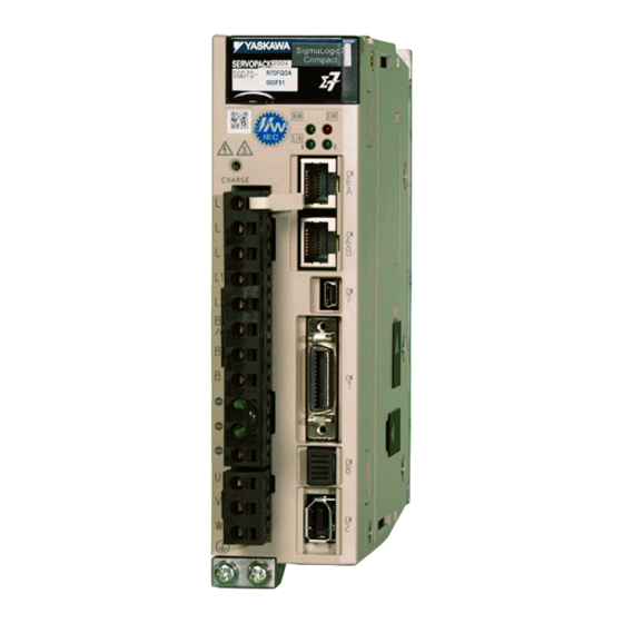
Page 10: Sigmalogic7 Compact Appearance
1 Introduction 1.2 SigmaLogic7 Compact Appearance The following figure shows the external appearance of the SigmaLogic7 Compact servo interface. Switches (under cover) LED Indicators Main Circuit Power Supply CN6A/B: Ethernet Control Circuit CN7: USB Power Supply Regenerative Resistor CN1: SERVOPACK I/O... - Page 11 1 Introduction CN101: CN6A/B: Ethernet Main Circuit Power Supply CN1: SERVOPACK I/O CN103: DC Bus Terminals CN8: HWBB CN2: Encoder CN201: Control CN7: USB Circuit Power Supply 400V Top View CN102: Servo Motor Power CN115: Dynamic Brake 400V Bottom View...
-
Page 12: Model Number Designation
B: 2.0 m C: 3.0 m Use high quality shielded industrial Ethernet cables Communication Ethernet Cable Customer Supplied (Yaskawa model JZSP-CM3RRM0-xx-E is recommended) Accessory CN1 Connector JUSP-7CN001 30 Pin I/O Connector (400 VAC) Module cover and Option Case Kit... -
Page 13: Specifications And Settings
2 Specifications and Settings 2.1.1 200 V Specifications 2 Specifications and Settings 2.1 Specifications 2.1.1 200 V Specifications Item Specification Control Method IGBT-based PWM control, sine wave current drive Serial encoder: 20 bits or 24 bits (incremental encoder/ With Rotary absolute encoder) Servomotor 22 bits (absolute encoder) - Page 14 2 Specifications and Settings 2.1.1 200 V Specifications (cont?d) Item Specification 1:5000 (At the rated torque, the lower limit of the speed control Speed Control Range range must not cause the Servomotor to stop.) ±0.01% of rated speed max. (for a load fluctuation of 0% to 100%) Coefficient of 0% of rated speed max.
- Page 15 2 Specifications and Settings 2.1.1 200 V Specifications (cont?d) Item Specification Inter- A JUSP-JC001 Communications Unit is required to connect to a faces Digital Operator (JUSP-OP05A-1-E). RS-422A Com- Commu- Up to N = 15 stations possible for RS-422A port muni- nica- cations tions...
- Page 16 2 Specifications and Settings 2.1.2 400 V Specifications 2.1.2 400 V Specifications Item Specification Control Method IGBT-based PWM control, sine wave current drive Serial encoder: 24 bits With Rotary (incremental encoder/absolute Servomotor encoder) Feedback • Absolute linear encoder (The signal resolution depends on the absolute linear encoder.) With Linear Servomotor...
- Page 17 2 Specifications and Settings 2.1.2 400 V Specifications Item Specification Phase A, phase B, phase C: Line-driver output Encoder Divided Pulse Output Number of divided output pulses: Any setting is allowed. Linear Servomotor Over- Number of input points: 1 heat Protection Signal Input voltage range: 0 V to +5 V Input Allowable voltage range: 24 VDC ±20%...
- Page 18 2 Specifications and Settings 2.1.2 400 V Specifications Item Specification CHARGE, PWR, RUN, ERR, and L/A (A and B) indicators, and Displays/Indicators one-digit seven-segment display Ethernet IP Address Setting Switches Used to configure IP address Number of points: 2 Output voltage range: ±10 VDC (effective linearity range: ±8 V) Resolution: 16 bits Analog Monitor (CN5) Accuracy: ±20 mV (Typ)
-
Page 19: Dip Switch Settings
2 Specifications and Settings 2.1.2 400 V Specifications 2.2 DIP Switch Settings DIP Switches Rotary Switches (used to set IP address) Rotary Switch 1 Rotary Switch 0 Setting for Switch Name Setting Operating Mode Normal Details Operation User program execution inhibited STOP Inhibits user program execution... -
Page 20: Rotary Switches
2 Specifications and Settings 2.1.2 400 V Specifications 2.3 Rotary Switches When DIP switch 4 (E-INIT) is OFF, the rotary switches are ignored. The IP address is set from configuration settings stored on the servo controller. Rotary switches are normally used to set the IP address. This is the case when DIP switch 4 (E-INIT) is ON ... -
Page 21: Installation Standards
3 Installation Standards 3 Installation Standards 3.1 Mechanical Installation/Dimensions The SigmaLogic7 Modbus servo interface is based on the Sigma-7S EtherCAT servo amplifier. As such, it has the same envelope and mechanical installation directions. For 200V models, please refer to section 2.3 of the Sigma-7S EtherCAT (CoE) Communications Reference Product Manual (document number SIEPS80000155). -
Page 22: Installing Multiple Servopacks In A Control Panel - -16
3 Installation Standards 3.2.1 200 V SERVOPACKS 3.2 Installing Multiple SERVOPACKS in a Con- trol Panel 3.2.1 200 V SERVOPACKS Provide the following intervals between the SERVOPACKs and spaces around the SERVOPACKs. Install cooling fans above the SERVOPACKs so that hot spots do not occur around the SERVOPACKs. - Page 23 3 Installation Standards 3.2.2 400 V SERVOPACKS 3.2.2 400 V SERVOPACKS 400 V SERVOPACKS can be mounted side-by-side as shown. Install cooling fans above the SERVOPACKs so that hot spots do not occur around the SERVOPACKs. Important 120 mm min. 30 mm min.
- Page 24 3 Installation Standards 3.2.2 400 V SERVOPACKS...
-
Page 25: Inputs And Outputs
4 Inputs and Outputs 4.1.1 200 V SERVOPACKS 4 Inputs and Outputs 4.1 Input Signals 4.1.1 200 V SERVOPACKS Default settings are provided in parentheses Signal Name Function /SI1 You can allocate the input signal to use with General-purpose Digital Input 1 a parameter. - Page 26 Inputs the Digital input signal power supply. Digital Input Signal +24VIN Allowable voltage range: 24 VDC ±20% The 24- Power Supply Input VDC power supply is not provided by Yaskawa. Battery for Absolute These are the pins to connect the absolute BAT+ Encoder (+) encoder backup battery.
-
Page 27: Output Signals
4 Inputs and Outputs 4.2.1 200 V SERVOPACKS 4.2 Output Signals 4.2.1 200 V SERVOPACKS Default settings are provided in parentheses Signal Name Function ALM+ Servo Alarm Output Turns OFF (opens) when an error is detected. ALM- /SO1+ General-purpose Digi- You can allocate the output signal to use with a parameter. - Page 28 4 Inputs and Outputs 4.2.2 400 V SERVOPACKS 4.2.2 400 V SERVOPACKS Default settings are provided in parentheses Signal Name Function ALM+ Servo Alarm Output Turns OFF (opens) when an error is detected. ALM- /SO1+ You can allocate the output signal to use with a parame- General-purpose (/BK+) ter.
-
Page 29: I/O Signal Connector (Cn1) Pin Arrangement
4 Inputs and Outputs 4.3.1 200 V SERVOPACKS 4.3 I/O Signal Connector (CN1) Pin Arrange- ment 4.3.1 200 V SERVOPACKS The following figure gives the pin arrangement of the of the I/O signal connector (CN1) for the default settings. General- Battery for /SO1+ purpose... - Page 30 4 Inputs and Outputs 4.3.2 400 V SERVOPACKS 4.3.2 400 V SERVOPACKS The following figure gives the pin arrangement of the of the I/O signal connector (CN1) for the default settings. Signal Specification Signal Specification Battery for absolute General-purpose PG BAT- /SO5- encoder (-) Digital Output 5...
-
Page 31: I/O Signal Wiring Examples
* 2. Connect these when using an absolute encoder. If the Encoder Cable with a Battery Case is connected, do not connect a backup battery. * 3. The 24-VDC power supply is not provided by Yaskawa. Use a 24-VDC power supply with double insulation or reinforced insulation. - Page 32 * 2. Connect these when using an absolute encoder. If the Encoder Cable with a Battery Case is connected, do not connect a backup battery. * 3. The 24-VDC power supply is not provided by Yaskawa. Use a 24-VDC power supply with double insulation or reinforced insulation.
- Page 33 Frame ground * 1. represents twisted-pair wires. * 2. The 24-VDC power supply is not provided by Yaskawa. Use a 24-VDC power supply with double insulation or reinforced insulation. * 3. Always use line receivers to receive the output signals.
- Page 34 Phase C * 1. represents twisted-pair wires. * 2. The 24-VDC power supply is not provided by Yaskawa. Use a 24-VDC power supply with double insulation or reinforced insulation. * 3. Always use line receivers to receive the output signals.
-
Page 35: I/O Circuits
4 Inputs and Outputs 4.5.1 Digital Input Circuits 4.5 I/O Circuits 4.5.1 Digital Input Circuits Photocoupler Input Circuits This section describes CN1 connector terminals 6 to 13. Examples for Open-Collector Examples for Relay Circuits Circuits SERVOPACK SERVOPACK Ω 4.7 k Ω... - Page 36 4 Inputs and Outputs 4.5.2 Digital Output Circuits 4.5.2 Digital Output Circuits Incorrect wiring or incorrect voltage application to the output circuits may cause short-circuit failures. If a short-circuit failure occurs as a result of any of these causes, the holding brake will not work.
-
Page 37: Led Outputs
5 LED Outputs 5 LED Outputs The following indicators show the operating status of the servo controller and error information. ERR: Solid at power up Off when there is no error Solid when there is an alarm ... - Page 38 5 LED Outputs...
-
Page 39: Ethernet Connectivity
6 Ethernet Connectivity 6 Ethernet Connectivity The SigmaLogic7 Compact supports both 100 Mbps/100Base-TX and 10 Mbps/10Base-T connections. One single network is accessed using both CN6A and CN6B. The same IP address is set for both ports. The Ethernet address (MAC address) can be found on the nameplate. -
Page 40: Ethernet Cable
6 Ethernet Connectivity 6.2 Ethernet Cable For the Ethernet cable, use a twisted pair cable with RJ-45 connector. Yaskawa strongly recommends the use of shielded ethernet cables (Yaskawa model JZSP-CM3RRM0-xx-E). Ethernet ports are capable of auto-crossover, so crossover cables are not necessary. - Page 41 6 Ethernet Connectivity Connection Example 2 SigmaLogic7 Compact SigmaLogic7 Compact 100 Base-TX (up to 100m) Station Connection Example 3 SigmaLogic7 Compact SigmaLogic7 Compact Station Core 100Base-TX Core 100Base-TX Ethernet Switch Servo motor LogicWorks...
- Page 42 1. Locate Ethernet cables so that they are well-separated from power cables or other sources of EMI 2. Yaskawa strongly recommends the use of high-quality shielded Ethernet cables such as JZSP-CM3RRM0-xx-E 3. Attach ferrite cores to Ethernet cables that are subjected to EMI...
-
Page 43: Cable Diagrams
7 Cable Diagrams 7 Cable Diagrams 7.1 SBK-U-VBA-xx (200 V Only) Terminal Block - CN1 I/O. SBK-U-VBA-xx Function Chart for Sigma-5 or Sigma-7 Servo Amplifier Mechatrolink-II type Servo Amplifier / Option type Pin No. Signal Function /BK+ (/SO1+) Brake interlock output (+) (General purpose output 1 (+)) /BK- (/SO1-) Brake interlock output (-) (General purpose output 1 (-)) ALM+... -
Page 44: Jzsp-Csi02-X-E (200 V Only)
7 Cable Diagrams 7.2 JZSP-CSI02-x-E (200 V Only) Flying Lead - CN1 I/O. SERVOPACK End Connector 10126 - 6000 EL ( by Sumitomo 3 M Ltd. ) Shell 10326 - 52 A 0 - 008 Cable ( Ivory ) SSRFPVV-SB AWG# 28 13 P ×... -
Page 45: Emc Installation Conditions
The EMC installation conditions that are given here are the conditions that were used to pass testing criteria at Yaskawa. The EMC level may change under other conditions, such as the actual installation structure and wiring conditions. These Yaskawa products are designed to be built into equipment. - Page 46 8 EMC Installation Conditions • Single-Phase, 200 VAC Shield box Brake power supply SERVOPACK Brake U, V, and W Power supply: Noise L1 and L2 Single-phase, 200 VAC filter Servomotor L1C and L2C Surge absorber Encoder Clamp Host controller CN6A and CN6B Clamp Clamp Safety...
- Page 47 8 EMC Installation Conditions • Single-Phase, 100 VAC Shield box Brake power supply SERVOPACK Brake U, V, and W Power supply: Noise L1 and L2 Single-phase, 100 VAC filter Servomotor L1C and L2C Surge absorber Encoder Clamp Host controller CN6A and CN6B Clamp Clamp Safety...
- Page 48 8 EMC Installation Conditions • Three-Phase, 400 VAC Shield box Brake power supply SERVOPACK Brake U, V, and W Power supply: Noise L1, L2, and L3 Three-phase, 400 VAC Filter Servomotor Surge Absorber Encoder Clamp Power supply: 24 VDC 24 V, 0 V Host controller CN6A and CN6B Clamp...
-
Page 49: Safety
Specification Installation Guide (document number TOBPC72082909) 9.3 Supported Safety Functions The SigmaLogic7 Compact on its own supports Hard Wire Base Block (HWBB) Safety function. For more information on HWBB, please see section 11 in Σ-7S SERVOPACK with EtherCAT (CoE) Communications Reference Product Manual (document number SIEPS80000155). - Page 50 [For customers using 3rd party controller other than Allen-Bradley] If the SigmaLogic7 Compact changes to HWBB state during operation due to motion command bits of output registers, a “4400h: Hard Wire Base Block” error will occur.
- Page 51 9 Safety COMMAND: Instance 112 – 256byte Master Output to SigmaLogic Input, E/IP Instance 112: 256 bytes Ethernet/IP Scanner SigmaLogic (E/IP Adapter) Output DWord Block use Description Type (DINT) ServoOn BOOL BOOL Home BOOL Start Move 1 BOOL BOOL BOOL SuperImpose BOOL ServoAlarmReset BOOL ControllerAlarmReset BOOL...
-
Page 52: Risk Assessment
9 Safety 9.5 Risk Assessment When using the Safety Module, be sure to perform risk assessment of the servo system in advance. Make sure that the safety level of the standards is met. For details about the standards, refer to front of this manual. - Page 54 Phone: 81-3-5402-4511 Fax: 81-3-5402-4580 http://www.yaskawa.co.jp YASKAWA AMERICA, INC. 2121 Norman Drive South, Waukegan, IL 60085, U.S.A. Phone: (800) YASKAWA (800-927-5292) or 1-847-887-7000 Fax: 1-847-887-7310 http://www.yaskawa.com YASKAWA ELÉTRICO DO BRASIL, LTDA. Avenida Piraporinha 777, Diadema, São Paulo, 09950-000, Brasil Phone: 55-11-3585-1100 Fax: 55-11-3585-1187 http://www.yaskawa.com.br...