Table of Contents
Advertisement
Quick Links
Advertisement
Table of Contents

Related Manuals for Fluke RUSKA 7750i


Summary of Contents for Fluke RUSKA 7750i
- Page 1 RUSKA 7750i Air Data Test Set Users Manual PN 3963351 November 2010 © 2010 Fluke Corporation. All rights reserved. Printed in USA. Specifications are subject to change without notice. All product names are trademarks of their respective companies.
- Page 2 Fluke authorized resellers shall extend this warranty on new and unused products to end-user customers only but have no authority to extend a greater or different warranty on behalf of Fluke. Warranty support is available only if product is purchased through a Fluke authorized sales outlet or Buyer has paid the applicable international price.
- Page 3 7750i – Change Language mode Hold key for 5 seconds enter...
-
Page 5: Table Of Contents
Table of Contents Chapter Title Page General Information ................1-1 Introduction......................1-1 How to Contact Fluke ..................1-1 Safety Information ..................... 1-1 Safety Summary .................... 1-1 Keep Away From Live Circuits..............1-1 Do Not Service or Adjust Alone..............1-2 Resuscitation....................1-2 Electro Static Discharge Sensitive Parts............ - Page 6 RUSKA 7750i Users Manual Introduction......................2-1 Power Supply..................... 2-2 Electronics Module .................... 2-2 Back-Plane Board..................2-2 Microprocessor Board ................... 2-2 Digital Control Board ..................2-3 IEEE-488 Interface..................2-3 Front Panel..................... 2-3 Pneumatics Module.................... 2-3 Measure Mode Pneumatics................2-4 Qc Reference..................... 2-4 Test Port ....................
- Page 7 — Zero Sequence ..................5-12 Sample Program 3 — RUSKA 7750i Serial (RS-232) — Controls Pressure to 20.000 %FS ............. 5-14 Sample Program 4 — QBASIC Example for RUSKA 7750i ....... 5-17 Maintenance..................6-1 Introduction......................6-1 Observing the Software Version Number............6-1...
- Page 8 Sensor Photocell Zeroing................... 6-9 Optimizing Control .................... 6-12 Fan Operation ....................6-13 System Software Update Procedure..............6-14 RUSKA 7750i Controller Software Upgrade ..........6-14 Replacement Parts....................6-15 Preparation for Storage and Shipment..........7-1 Preparation for Storage & Shipment..............7-1 Disconnecting the ADTS ................... 7-1 Packing Instructions...................
- Page 9 RUSKA 7750i ADTS - Options List..............1-5 2-1. Conversion Factors....................2-3 2-2. Solenoid Valves States ................... 2-4 3-1. General Specifications and Parameters ..............3-2 6-1. Electronics Self Test ....................6-2 6-3. RUSKA 7750i ADTS - Replacement Parts List ............ 6-15...
- Page 10 RUSKA 7750i Users Manual...
- Page 11 Page 2-1. ADTS Block Diagram.................... 2-1 2-2. RUSKA 7750i ADTS - Pneumatics Model............2-5 2-3. RUSKA 7750i ADTS - Pneumatics Schematic Diagram ........2-6 2-4. Photocell/Light Spot....................2-8 2-5. Menu | Display - Menu................... 2-10 3-1. RUSKA 7750i Back Panel ..................3-3 4-1.
- Page 12 RUSKA 7750i Users Manual 6-10. Auto-Tune Screen ....................6-13 7-1. Packing the ADTS....................7-3 viii...
-
Page 13: General Information
General Information Introduction This manual contains operation, routine and preventive maintenance instructions for the RUSKA 7750i Air Data Test Set (ADTS) manufactured by Fluke. This section of the manual provides general information about the ADTS and presents its features and options. -
Page 14: Do Not Service Or Adjust Alone
In this manual, a Warning identifies conditions and actions that pose a hazard to the user. A Caution identifies conditions and actions that may damage the ADTS or the equipment under test. Symbols used on the RUSKA 7750i Air Data Test Set (ADTS) and in this manual are explained in Table 1-1. -
Page 15: General Information
In measure mode, the ADTS measures pressure. It can be used to monitor barometric pressures, vacuum systems, and differential pressure devices. The RUSKA 7750i has two full-scale pressure ranges and two pressure controllers integrated into one instrument. Features The following features are available on all RUSKA 7750i ADTSs. -
Page 16: Measure While Control
RUSKA 7750i Users Manual Measure While Control The ADTS simultaneously digitally displays the commanded pressure, the actual pressure, and the difference between the two. A bar graph indicates how close the actual pressure is to the commanded pressure, as well as how close the commanded pressure is to the ADTS’s full-scale pressure. -
Page 17: Choice Of Display Units
Lines and Fittings Kit: This kit contains the pressure and vacuum lines and fittings to connect the RUSKA 7750i to the optional Fluke vacuum pump and to a gas bottle regulated with 1/4 NPT fittings. Additionally, this kit contains two flexible hose assemblies, one for the Ps terminating to a female AN6 fitting and one for the Qc pressure port terminating to a female AN4 fitting. - Page 18 RUSKA 7750i Users Manual...
-
Page 19: Theory Of Operation
This Chapter of the manual describes the ADTS’s component modules (Figure 2-1) and provides a general discussion of each. The RUSKA 7750i has two pneumatic control and two primary transducer modules. P rim a ry T ra n sd u ce r P s M o d u le... -
Page 20: Power Supply
RUSKA 7750i Users Manual Power Supply The ADTS’s universal power supply accepts AC voltages from 100 – 120 VAC and 220 – 240 VAC at 50 / 60Hz. This quad-output supply produces +5 VDC, +/-12 VDC, and 24 VDC, which are distributed to the Control and Backplane Boards. -
Page 21: Digital Control Board
A digital controller on the board drives two solenoids in the pneumatics section to form a high-speed, closed loop controller. There are two digital control boards in the RUSKA 7750i ADTS. IEEE-488 Interface The ADTS’s IEEE-488 (GPIB) interface card, which plugs directly into the Back-plane Board, provides the ADTS with an IEEE-488 interface. -
Page 22: Measure Mode Pneumatics
Ps test port allowing the instrument to zero at a low vacuum level. Test Port The Test Port connects the DUT to the Pneumatics Module. The RUSKA 7750i has two test ports, one for the Ps and for the Pt channel. The Test Port is isolated from the DUT by a normally closed solenoid valve that is open during the ADTS’s Measure, Control... - Page 23 Theory of Operation Pneumatics Module gme03.eps Figure 2-2. RUSKA 7750i ADTS - Pneumatics Model...
-
Page 24: Go To Ground Or Vent Procedure
POR T S UPPLY gme04.eps Figure 2-3. RUSKA 7750i ADTS - Pneumatics Schematic Diagram Go to Ground or Vent Procedure The Go-To-Ground is implemented as a multi-step procedure: a. Control Ps to close to Atmosphere and Qc to zero at the current rate. -
Page 25: Control Mode Pneumatics
Theory of Operation Control Strategy Control Mode Pneumatics Pressure Supply Port The Pressure Supply Port connects the user’s regulated gas supply to the Pneumatics Module. Please refer to Appendix A for gas specifications and supply pressure limits. The supply pressure is connected to the right-hand port of the rear chassis. This regulated pressure should be set to the full-scale Pt range + 10 psi (0.7 bar). - Page 26 RUSKA 7750i Users Manual As pressure is applied in the helical tube, the entire apparatus attempts to rotate. This causes the mirror to move the reflected light spot to shine more on one photodiode than the other. The Sensor Board (see Chapter 2, Sensor Board section) then responds by changing the current to the electromagnetic coils that, through interaction with the permanent magnets, force the helical tube to return to its zero position.
-
Page 27: Sensor Board
On the RUSKA 7750i, multiple quartz sensor ranges are used in order to provide the percent of reading specification. In these instruments, a total of three points per range with one point shared between two ranges is required. -
Page 28: Oven Control
RUSKA 7750i Users Manual Oven Control The oven temperature is controlled via a pulse-width modulated signal. The time the heater is on can be varied from 0% to 100%. The pulse-width at startup is initialized to the previous value that was stored in battery-backed CMOS RAM. - Page 29 Theory of Operation Software Zero Coefficients Zero correction for High FSR (Full-Scale Resistors) Value is in counts (7,381,975 = full scale of current sensor). Zero correction for Low FSR. Value is in counts (7,381,975 = full scale of low FSR) Hardware zero correction.
- Page 30 RUSKA 7750i Users Manual 2-12...
-
Page 31: Installation
Chapter 3 Installation Introduction This section of the manual discusses initial installation for the RUSKA 7750i ADTS. Installing the ADTS involves connecting the supply and test pressure tubing, powering up the unit, and configuring the system through the front panel. -
Page 32: Cautions
RUSKA 7750i Users Manual Table 3-1. General Specifications and Parameters Parameter Value Operating Humidity 5% – 95%RH, non-condensing Storage Humidity None Operating Temperature 18 °C – 36 °C Storage Temperature -20 °C to 70 °C Electrical Power 100 – 120/220 – 240 VAC... -
Page 33: Observing The Adts's Full Scale Rating
1/8 inch (3 mm). gme07.bmp Figure 3-1. RUSKA 7750i Back Panel Vacuum Sensor The ADTS has a vacuum sensor connected to the Ps sensor. This sensor is used to zero... - Page 34 RUSKA 7750i Users Manual...
-
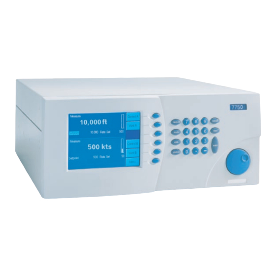
Page 35: Local Operation
This section of the manual describes operation of the ADTS using the front panel (local interface). gme08.eps Figure 4-1. RUSKA 7750i Front Panel 1. Color TFT display shows the system status and menu options. 2. Function keys — the label shown in the display identifies their function, which will change based on the screen of operation. - Page 36 RUSKA 7750i Users Manual 4. Rotary Knob — selects a field for editing, and is used for small pressure changes (pressure jog) at the main menu of the single display mode. Dual Channel Dis play Mode Places Ps and Qc in Control mode, press again to place Ps back to Measure...
-
Page 37: Dual Channel Display Screen
Local Operation Local Operation Dual Channel Display Screen The ADTS displays a screen similar to the one shown below at power up. This is the top of the menu tree. The rotary knob may be used to highlight a set point to edit. Then enter the new value using the keypad. -
Page 38: Single Channel Display Screen
Below the pressure reading is the current unit of measure and mode (Gauge, Differential or Absolute). The RUSKA 7750i is designed such that all of the commonly used functions are accessible by a direct key on the key pad or from a top level function keys. Less commonly used set-up type functions are accessible through the menu function keys. -
Page 39: Changing Units Of Measure
Local Operation Tutorial Changing Units of Measure 1. Change the pressure units. The units are changed by selecting the UNITS key on the keypad. gme12.bmp Figure 4-5. Units - Menu 2. Use the rotary knob located to the right of the display to move the highlight bar to the desired unit. -
Page 40: Selecting Language
No confirmation is necessary to leave Control mode. Selecting Language The RUSKA 7750i ADTS operates in a variety of different languages. To select a different language, press and hold the MODE key for 5 seconds. The current language will be highlighted. -
Page 41: Controlling Pressure
Local Operation Controlling Pressure Controlling Pressure Pressing either the Control Ps or Control Qc function key places both channels of the ADTS into the Control Mode. If it is desired to have only one channel in the control mode, press either the Control Ps or Control Qc function key a second time and that channel will be switched back into the measure mode. -
Page 42: Step/Jog
RUSKA 7750i Users Manual Step/Jog This feature is only available when operating in the single display mode. To place the ADTS in the single display mode from the dual display screen press the MENU key. In addition to entering the pressure set point through the keypad, the pressure set point can be changed using either the step or the jog functions. -
Page 43: Menu | Setup
Setup is used to configure the system. It includes setting all of the limits, user parameters, user-defined units of measure, remote interface and system setup. On the RUSKA 7750i, the User and Limits screens are separate for each channel and must be set up independently. The Units, Remote, and System screens are identical in each channel. - Page 44 Control Band There are two common pressure control approaches that are available with the RUSKA 7750i ADTS. One of the most common control styles is an Active controller where the controller remains operative and holds the pressure at a commanded set point. This allows the system to hold the pressure at a set point within the control stability specification (See Appendix A).
- Page 45 Local Operation Menu ARINC 565 Operating Limits The ADTS can be set to the ARINC 565 operating limits. When this is selected as YES, the ADTS ignores the user defined minimum and maximum airspeed and altitude limits, and enables the ARINC limits. These limits are defined in the Limits Screen, shown in Figure 4-9. Supply Correction If the supply pressure is set at a value less than the value recommended in A-2 of Appendix A, then the control performance may be affected.
-
Page 46: Menu | Setup - User
RUSKA 7750i Users Manual Access The test access password allows the user to protect access to ADTS configuration and programs. If the test access password is set to any number other than zero (factory default), it is required before the user is allowed to change the limits, control parameters or programs. The access key is only shown on the Ps channel. - Page 47 5. Press Position [F4] to select if the position of the Device Under Test is either “Above” or “Below” the RUSKA 7750i. The selected units will be highlighted and appear in the Gas Head description. 6. Use the rotary knob to highlight the label “Gas Head.”...
-
Page 48: Menu | Setup - Units
RUSKA 7750i Users Manual Changing the Number of Decimals Each unit has a default number of decimal places used for pressure display. This may be adjusted up or down by one decimal place. 1. The decimal digits are set from the Menu | Menu |Setup | User. From the Main Menu (press PREVIOUS until the Main Menu appears), press Menu [F6], Menu [F6], then Setup [F2], and then User [F2]. -
Page 49: Menu | Setup - Remote
Local Operation Menu 1. The pressure units are defined from the Menu | Menu| Setup | Units. From the Main Menu (press PREVIOUS until the Main Menu appears), press Menu [F6], Menu [F6], then Setup [F2], then Units [F3]. 2. Use the rotary knob to highlight the desired user-defined unit, and then select the Edit Name [F1] function key. -
Page 50: Menu | Setup - System
RUSKA 7750i Users Manual GPIB Address Sets the IEEE-488 interface address. Protocol The Protocol defines which protocol should be used by the remote interface. The options are Standard Communication for Programmable Instruments (SCPI) and RUSKA 6610 emulation. Serial Interface Set-Up The operator can set-up the Baud Rate, Data Bits, Parity, and Stop Bits for the Serial Interface. -
Page 51: Menu | Calibrate
100 mtorr in order to obtain a proper zero. Note, for the highest measurement performance, it is recommended to zero the RUSKA 7750i at a vacuum level of 60 mtorr or less. This is typically achievable within 30 minutes; however, in high humidity situations the drying time can extend to 45 minutes. -
Page 52: Menu | Test
The Menu | Test section of the system is used to perform a number of the diagnostic and tuning functions that are available with the RUSKA 7750i. The Sweep and Control test operate on the current selected channel. The other screens are independent of the selected channel. -
Page 53: Menu | Test - Shop1
Local Operation Menu gme24.bmp Figure 4-17. Menu | Menu | Test | Remote - GPIB Menu | Test — Shop1 The Menu | Menu | Test | Shop1 menu of the system is used to display the current status of the various valve positions in the system. -
Page 54: Menu | Test - Control
RUSKA 7750i Users Manual Menu | Test — Control The Menu | Menu | Test | Control menu of the system is used to tune the controller. On new instruments, the controller is tuned at the factory and therefore, the user should not need to access or make any adjustments to the controller using this menu. -
Page 55: Menu | Display - Temperature
When railed to a high value, it indicates 350 mtorr. When the vacuum level present in the Ps sensor is less than 350 mtorr, this sensor indicates the actual vacuum level. Menu | Display — Blank This is used as a screen saver in the RUSKA 7750i. 4-21... - Page 56 RUSKA 7750i Users Manual 4-22...
-
Page 57: Remote Operation
Chapter 5 Remote Operation Capabilities The ADTS can be operated remotely by a computer. Two interfaces are supported: IEEE-488 and RS-232. Both interfaces support SCPI (Standard Commands for Programmable Instruments). The IEEE-488 interface additionally supports emulation of a RUSKA 6610 ADTS. The IEEE-488 interface conforms to the following standards: ANSI/IEEE Std 488.1-1987 IEEE Standard Digital Interface for Programmable Instrumentation... -
Page 58: Remote/Local Operation
RUSKA 7750i Users Manual RS-232 The RS-232 interface supports standard serial operation from a computer to a single ADTS. RS-232 supports the IEEE-488.2 and SCPI commands. The ADTS allows the following port setups: Baud Rate: 1200, 2400, 9600, or 19200... -
Page 59: Configuration
Remote Operation Configuration Configuration The remote interface must be configured before it is connected. The remote interface is configured using the local interface. The parameters needed vary with the interface used. IEEE-488 Address, Protocol RS-232 Baud Rate, Data Bits, Parity, Stop Bits To configure the remote interface: 1. -
Page 60: Ansi/Ieee 488.2-1987 Command Summary
RUSKA 7750i Users Manual ANSI/IEEE 488.2-1987 Command Summary *CLS Clear Status *ESE? Event Status Enable Query *ESE <number> Event Status Enable *ESR? Event Status Register *IDN? Identification *OPC? Operation Complete Query (Returns 1) *OPC Operation Complete *RST Reset *SRE? Service Request Enable Query *SRE <number>... - Page 61 Remote Operation Device Messages :LIMit :MAXimum :PRESsure ALT,<number> Maximum Altitude limit** :PRESsure CAS,<number> Maximum Airspeed limit** :PRESsure MACH,<number> Maximum Mach limit :PRESsure PS,<number> Maximum Ps pressure limit :PRESsure QC,<number> Maximum Qc pressure limit :PRESsure PT,<number> Maximum Pt pressure limit :RATE ALT,<number> Maximum Altitude rate limit** :RATE CAS,<number>...
- Page 62 RUSKA 7750i Users Manual :TIME? Qc last calibration time :ZERO :DATE? Qc last zero date :TIME? Qc last zero time :INITiate Qc enter zero mode :INITiate? Qc status for cal, press, temp, ref :RUN Qc start zero calibration :STOP abort zero calibration PRESsure4 Ps Control Sensor :VALue<n>...
- Page 63 Remote Operation Device Messages [SOURce] :GTGRound Go to ground :GTGRound? Returns 1 if safe at ground :LIMit :ARINc ON|OFF|1|0 ARINC limit checking :AIRCraft STANDARD|MAX|ARINC :MACH ON|OFF|1|0 Mach limit disable :PRESsure ALT,<number> Altitude Setpoint** :PRESsure CAS,<number> Airspeed setpoint** :PRESsure MACH,<number> Mach Setpoint :PRESsure PS,<number>...
-
Page 64: Example Scpi Commands
RUSKA 7750i Users Manual :LENGth MM|IN set length units (head height) [:PRESsure] <name> set pressure units :TEMPerature C|CEL|F|FAR|K set temperature units :VACuum MICRON|MTORR|PA|<name> set vacuum units Units for this command are set by UNIT:AER. Example SCPI Commands To request the current pressure reading, all of the following commands are equivalent:... - Page 65 Remote Operation Device Messages *SRE Status Byte (*STB) Bit 7 Operation Summary Bit 6 Service Request Bit 5 Event Summary Bit 4 Message Available Bit 3 Questionable Summary Bit 2 Error Available Bit 1 reserved Bit 0 reserved Event Status Register (*ESR) Bit 7 Power lost Bit 6...
-
Page 66: Serial Operation
When addressing is disabled, the unit will respond to commands without being addressed. Sample Programs Sample Program 1 — RUSKA 7750i GPIB (IEEE-488) — Controls Pressure to 20.000 %FS /*--------------------------------------------------------------------*/ Sample Program 1 - 7750 GPIB (IEEE-488) Controls pressure to 20.000 %FS... - Page 67 Remote Operation Sample Programs /*-------------------------------------------------*/ /* Read pressure status until setpoint is reached. */ MEAS? Read pressure STAT:OPER:COND? Read status setpoint /*-------------------------------------------------*/ while (!kbhit ( )) { request_7000 ("MEAS?;:STAT:OPER:COND?\n"); pressure = strtod (buffer, &p); status = atoi (++p); if (check_errors ( )) continue;...
-
Page 68: Sample Program 2 - Ruska 7750I Gpib (Ieee-488) - Zero Sequence
/*--------------------------------------------------------------------*/ void request_7000 (char *s) ibwrt (device, s, strlen (s)); ibrd (device, buffer, sizeof (buffer)); /*--------------------------------------------------------------------*/ Sample Program 2 — RUSKA 7750i GPIB (IEEE-488) — Zero Sequence /*--------------------------------------------------------------------*/ Sample Program 2 - 7750 GPIB (IEEE-488) Zero Sequence /*--------------------------------------------------------------------*/ #include <stdio.h>... - Page 69 Remote Operation Sample Programs clrscr ( ); cprintf ("Zeroing"); gotoxy (1, 5); cprintf ("Pressure Reading"); gotoxy (1, 6); cprintf ("Sensor Temperature"); gotoxy (1, 7); cprintf ("Reference Pressure"); /*-------------------*/ /* Enter Zero Mode CAL:ZERO:INIT */ /*-------------------*/ write_7000 ("CAL:ZERO:ALL:INIT\n"); /*---------------------------*/ /* Wait for zero to complete */ STAT:OPER:COND? /*---------------------------*/ { request_7000 ("STAT:OPER:COND?\n");...
-
Page 70: Controls Pressure To 20.000 %Fs
(char *s) ibwrt (device, s, strlen (s)); ibrd (device, buffer, sizeof (buffer)); /*------------------------------------------------------------------ --*/ Sample Program 3 — RUSKA 7750i Serial (RS-232) — Controls Pressure to 20.000 /*--------------------------------------------------------------------*/ Sample Program 3 - 7750 Serial (RS-232) Controls pressure to 20.000 %FS /*--------------------------------------------------------------------*/ #include <stdio.h>... - Page 71 Remote Operation Sample Programs if (check_errors ( )) { serial_close ( ); return; /*-------------------------------------------------*/ /* Read pressure status until setpoint is reached. */ MEAS? Read pressure STAT:OPER:COND? Read status setpoint /*-------------------------------------------------*/ while (!kbhit ( )) { if (!request_7000_serial ("MEAS?;:STAT:OPER:COND?\n")) { printf ("Timeout\n"); continue;...
- Page 72 RUSKA 7750i Users Manual void interrupt serial_int ( ) char ch; if ((inportb (portbase + 2) & 0x07) == 0x04) { ch = inportb (portbase); if (ch == XON) transmit_enabled = TRUE; else if (ch == XOFF) transmit_enabled = FALSE;...
-
Page 73: Sample Program 4 - Qbasic Example For Ruska 7750I
= ch; buffer[QUEUE_SIZE - 1] = 0; /* Buffer full */ return FALSE; /*--------------------------------------------------------------------*/ Sample Program 4 — QBASIC Example for RUSKA 7750i REM $INCLUDE: 'C:\GPIB-PC\QBDECL.BAS' DIM READING AS STRING*30 CALL IBDEV(0,4,0,12,1,&H40A,R7010%) CALL IBCLR(R7010%) CALL IBWRT(R7010%,"MEAS?" + chr$(&H0A)) - Page 74 RUSKA 7750i Users Manual 5-18...
-
Page 75: Maintenance
Chapter 6 Maintenance Introduction Very little maintenance is required for the ADTS. This section of the manual discusses suggested maintenance procedures. Observing the Software Version Number Follow the steps below to observe the ADTS’s software version number. 1. If necessary, press PREVIOUS several times to return the display to the Main Dual Display Menu. -
Page 76: Removing The Adts's Cover
RUSKA 7750i Users Manual 3. Press ELECTRICAL [F1]. The electronics self test will run and display the results. The electronics test runs eight sets of tests on various parts of the electronic modules. Table 6-1 describes these tests and the possible actions needed if a test fails. -
Page 77: Processor Battery
Maintenance Calibration Processor Battery The processor board uses a lithium battery to maintain time and date information. This battery has a varying life. If the instrument is left on 24 hours a day, it may last 5 to 10 years. If the instrument is stored, it may only last one year. Annual replacement is recommended. - Page 78 The sensors coefficients are then shown below the sensor label. On the RUSKA 7750i, there are two primary sensors. The first sensor that is shown is the Ps sensor. To switch to the Qc sensor, press the Sensor [F6] function key.
- Page 79 Calibration Step 2 1. To begin step 2, use the calibration standard to apply the various pressures that will be requested by the RUSKA 7750i. The screen will display a table noting the following information. Step The pressure step in the calibration sequence Apply The pressure that the standard is to generate to the ADTS.
-
Page 80: Storing The Coefficients
If there are variances beyond the stated precision, then an error was probably made in generating one of the calibration pressures, and the calibration procedure should be repeated. 9. Remove the vacuum standard from the instrument. 10. Reinstall the cover onto the RUSKA 7750i. -
Page 81: Editing The Calibration Coefficients
Maintenance Calibration Editing the Calibration Coefficients If the ADTS’s memory is erased but the calibration coefficients are known, the user can restore the coefficients to the ADTS by following the directions below. W Caution Never randomly adjust the calibration coefficients. Only qualified personnel with valid backup data should be allowed to edit the coefficients. -
Page 82: Qc Channel
RUSKA 7750i Users Manual The screen will display the current status of the pressure sensor Stability and Temperature. If any of the above are unstable, then the system will delay until stability is achieved. Pressing OK [F6] will bypass this wait period. -
Page 83: Ps Absolute Sensor - Vac Level
A high capacity vacuum pump must be connected to the rear vacuum port. The RUSKA 7750i has a Vacuum Sensor mounted internal to the primary sensor housing that monitors the vacuum level of the Ps sensor when the sensor is being zeroed. This sensor reading will display a value of 350 mtorr when the vacuum level is at or greater than 350 mtorr. - Page 84 RUSKA 7750i Users Manual 4. Select the Primary sensor by pressing the Sensor [F6] key until the words Ps Primary or Qc Primary depending on the desired sensor is displayed, above the calibration coefficients. 5. Select Zero [F1]. Do NOT press the Calibrate button.
- Page 85 Maintenance Sensor Photocell Zeroing 8. Adjusting the photocell will cause the yellow bar to reduce in width. It should be adjusted until the yellow line is as thin as possible over the green bar. gme34.bmp Figure 6-7. Adjusting the Photocell 9.
-
Page 86: Optimizing Control
Ps or the Qc channel. There are two options available to the operator. Full — This fully characterizes the control function of the RUSKA 7750i. It automatically adjust the control valve biases and aligns the inner loop high control pressure sensor to the high accuracy quartz sensor. -
Page 87: Fan Operation
System Software Update Procedure Note Calibration and other stored constants are not affected by program updates. The update procedure requires a PC connected to the RS-232 port on the RUSKA 7750i. 6-13... -
Page 88: Ruska 7750I Controller Software Upgrade
0R99 is older code than 1R01 which is older than 1R08, etc.) 1. Connect a PC to the RS-232 port on the RUSKA 7750i using a null modem cable. 2. The zip file labeled RUSKA 7750iControl|XRXX contains files UPDATE7.EXE and <version>.IMG. -
Page 89: Replacement Parts
3961365 3915780 Pt Equalize Valve 3961365 3915780 Pt Apply Valve 3961352 3915780 Pt Release Valve 3961352 3915780 Table 6-3. RUSKA 7750i ADTS - Replacement Parts List Description Part Number Power Supply 3865784 Fan Assembly 3962098 Rotary Encoder 3878927 Battery 2135249... - Page 90 RUSKA 7750i Users Manual 6-16...
-
Page 91: Preparation For Storage And Shipment
ADTS. Fluke has found that corrugated cardboard boxes provide the best packaging exterior. The box must have an impact rating of 275 lb and be of double-walled construction. This type of box will sustain most types of damage incurred during the shipping and handling process, but ensures that the contents remain intact and damage-free. - Page 92 The ADTS must be prepared for shipment in the following manner: 1. Fluke has an RMA procedure in place. Please contact the Customer Service Center to obtain an RMA number prior to returning any equipment. Have the following information available when contacting Fluke: a.
-
Page 93: Shipping Instructions
Figure 7-1. Packing the ADTS Shipping Instructions Fluke recommends using air freight for transportation. Surface transportation subjects the shipment to more frequent handling and much more intense shock. In most cases, if surface transportation is the mode of transport employed, handling damage is likely. - Page 94 RUSKA 7750i Users Manual...
-
Page 95: A Summary Of Specifications
Appendix A Summary of Specifications Uncertainty Analysis To perform an Uncertainty Analysis on a measurement device, you must be able to identify all of the parameters that influence the measurement. You must be able to quantify the magnitude of the potential error source and combine these into an overall uncertainty statement. - Page 96 RUSKA 7750i Users Manual Long Term Stability Long Term Stability defines how the instrument drifts with time. This specification can be utilized to define the calibration interval for the standard. Some manufacturers will provide more than one stability specification for their instrument based on different calibration time intervals.
- Page 97 In this approach, it is important to define the level of confidence that all of the uncertainty components are defined. For instance, all of the uncertainty specifications that Fluke publishes are at the 2 sigma level which would be at a 95% confidence level. Some manufacturers may state their uncertainty at different confidence level and therefore, you would need to be able to convert from one to the other in order to compare the two devices.
- Page 98 RUSKA 7750i Users Manual Table A-2. Uncertainty Analysis for a RUSKA 7750i — 3 month and Yearly Calibration 90 Day Uncertainty 1 year Uncertainty Uncertainty Analysis — 40 inHg Ps Sensor 40 inHg Ps Sensor RUSKA 7750i (2 sigma) (2 sigma) A.1 Performance —...
- Page 99 Summary of Specifications Uncertainty Analysis Table A-4. Uncertainty Analysis for a RUSKA 7750i — 3 month and Yearly Calibration 90 Day Uncertainty 1 year Uncertainty — Uncertainty Analysis 68 inHg Qc Sensor 68 inHg Qc Sensor RUSKA 7750i (2 sigma) (2 sigma) A.1 Performance —...
- Page 100 RUSKA 7750i Users Manual Specifications General Specifications Pressure Range: Standard available ranges; Ps: 32 inHg Abs. (0 to 1085 mbar Abs.) or, 40 inHg Abs. (0 to 1355 mbar Abs.) Qc: 32 inHg Diff. (0 to 1085 mbar Diff.) or, 68 inHg Diff.
- Page 101 Zero drift typically improves with sensor age. Total Uncertainty is defined as the two sigma combined uncertainty of linearity, hysteresis, repeatability, thermal effects one year drift stability and the uncertainty in the Fluke primary standard, which include the uncertainty from NIST.
- Page 102 Zero drift typically improves with sensor age. Total Uncertainty is defined as the two sigma combined uncertainty of linearity, hysteresis, repeatability, thermal effects one year drift stability and the uncertainty in the Fluke primary standard, which include the uncertainty from NIST.
-
Page 103: B Summary Of Error Messages
Appendix B Summary of Error Messages Summary of Error Messages Negative error numbers are from the Standard Commands for Programmable Instruments (Version 1991.0). Table B-1. Summary of Error Messages Value Description and Corrective Action No Error. -103 Invalid Separator. Check punctuation in the SCPI command. -104 Data Type. - Page 104 Sensor Calibration Lost. The sensor has lost its calibration, and must be recalibrated. Zero Aborted. Zeroing has been aborted by local or remote. Factory Data Lost. Internal factory constants have been lost. Contact Fluke for more information. Calibration Mode. The calibrate button must be pressed before SCPI calibration commands can be executed.
- Page 105 Summary of Error Messages Summary of Error Messages Table B-3. Summary of Error Messages, continued Value Description and Corrective Action Error Reading Barometric RPT Pressure Sensor. Control Sensor Out of Range. Controller Communication Error. Auto-Tune Failed.
- Page 106 RUSKA 7750i Users Manual...