Avaya G650 Installing
Hide thumbs
Also See for G650:
- Installing (258 pages) ,
- Getting started (21 pages) ,
- Specifications (2 pages)

Related Manuals for Avaya G650


Summary of Contents for Avaya G650
- Page 1 Installing the Avaya G650 Media Gateway Release 4.0 03-300685 Issue 2 February 2007...
- Page 2 Avaya support Avaya provides a telephone number for you to use to report problems or to ask questions about your product. The support telephone number is 1-800-242-2121 in the United States. For additional support telephone...
-
Page 3: Table Of Contents
Approved grounds ......Installing the G650 Media Gateway ...... - Page 4 G650 Media Gateway power switch ..... . . Cabling the G650 Media Gateways ......
- Page 5 Contents Testing external ringing ....... Testing the queue warning indicator .
- Page 6 Contents 6 Installing the Avaya G650 Media Gateway...
-
Page 7: Chapter 1: Introduction
Chapter 1: Introduction Use the procedures in this document to install a new Avaya G650 Media Gateway, connect it to the customer’s network, and test the complete configuration. The G650 Media Gateway provides card slots for up to 14 TN-type circuit packs, redundant, hot-swappable power supplies, and AC or DC power. -
Page 8: How To Use This Documentation
(http://support.avaya.com). You must have access to the Internet and a copy of Adobe Reader installed on your personal computer. Avaya makes every effort to ensure that the information in this book is complete and accurate. However, information can change after we publish this documentation. Therefore, the Avaya Support Web site might also contain new product information and updates to the information in this book. -
Page 9: Sending Us Comments
These documents are included on the CD-ROM Documentation for Avaya Communication Manager, Media Gateways and Servers, (03-300151). You can download the contents of this CD-ROM from the Avaya Support Web site, http://support.avaya.com. -
Page 10: Preinstallation Requirements
Manager (03-601508). Provides procedures on how to install and use a 120A Channel Service Unit, which may be used in some G650 configurations. The following job aids are also available on the CD-ROM Documentation for Avaya ● Communication Manager, Media Gateways and Servers: - Approved Grounds. -
Page 11: High-Level Overview Of The Installation Process
For more information, see Approved Grounds, (555-245-772). You have the required, customer-provided network information in the form of a completed ● Electronic Preinstallation Worksheet (EPW). For a blank form, see the Avaya Installation Wizard Web site, http://support.avaya.com/avayaiw All the equipment is on site. Compare the list of items that were ordered to the contents of ●... -
Page 12: Connecting The Media Gateways
In this stage, you connect the media gateways to the server complex through Ethernet cables. You also program the IP Server Interface (IPSI) circuit packs during this stage. Before you can complete this stage, the G650 Media Gateway must be installed and the server complex must be operational. -
Page 13: Chapter 2: Installing And Cabling The G650 Media Gateway
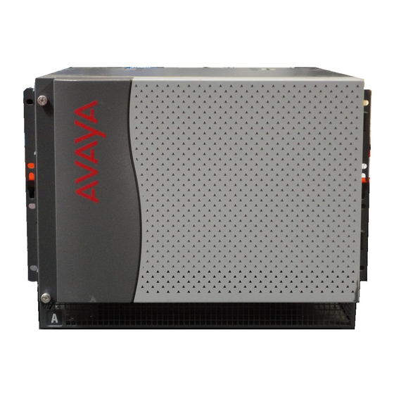
A port network (PN) consists of up to four G650 media gateways in a rack. The media gateway in the A location, at the bottom of the rack, contains the TN2312AP IP Server Interface (IPSI) circuit pack. -
Page 14: Specifications
1. Check the customer order list and the shipping packing list to confirm that all equipment is included. 2. Check the system adjuncts for damage and report all damage according to local shipping instructions. 3. If any equipment is missing, report the information to your Avaya representative. 14 Installing the Avaya G650 Media Gateway... -
Page 15: Unpacking And Inspecting The G650 Media Gateway
Preinstallation tasks Unpacking and inspecting the G650 media gateway DANGER : Use lifting precautions. An empty G650 Media Gateway weighs 35 to 39 pounds DANGER: (16 to 18 kilograms). Use caution to avoid injury. To unpack and inspect the G650 Media Gateway: 1. -
Page 16: Correcting Shipping Errors
Installing and cabling the G650 Media Gateway Figure 1: Equipment that is shipped with a single G650 Media Gateway Power Power FAN OR POWER FAIL FAN OR POWER FAIL FAN AND POWER OK FAN AND POWER OK AC INPUT AC INPUT... -
Page 17: Precautions For Ac Power And Ground
For more information, see Approved Grounds, 555-245-772. DANGER: The latch on the power supply does not turn off the power to the G650 Media DANGER: Gateway. To turn off the AC power from the G650, pull the AC power cord from the back of the G650 Media Gateway. -
Page 18: Installing The G650 Media Gateway
G650 Media Gateway power switch on page 39 ● Figure 2: G650 Media Gateway stack (A through E) that is installed next to the media server rack on page 19 shows a typical Communication Manager installation. 18 Installing the Avaya G650 Media Gateway... - Page 19 Installing the G650 Media Gateway Figure 2: G650 Media Gateway stack (A through E) that is installed next to the media server rack Power Power FAN OR POWER FAIL FAN OR POWER FAIL FAN AND POWER OK FAN AND POWER OK...
-
Page 20: Checking The Ventilation And The G650 Media Gateway Rack
Mounting Template that is shipped with each carrier, to help you align the holes. Each G650 Media Gateway is 8U high. A typical data rack is 42U high. When you create a five-carrier G650 Media Gateway stack, all but 3.5 inches (8.9 centimeters) of a typical rack is used. -
Page 21: Setting The Carrier Address Id
The slots are marked as A, B, C, D, and E. Avaya ships all carriers with the address paddleboard in connector slot A. If you are working on a B, C, D, or E carrier, you must remove the address paddleboard. -
Page 22: Mounting One G650 Media Gateway
LAO 072403 Mounting one G650 Media Gateway Note: In a multiple G650 Media Gateway configuration, put the G650s in the rack with Note: no vertical space between them. If the G650 Media Gateways are not mounted adjacent to one another with the fronts in the same vertical plane, you cannot use the TDM/LAN cables to cannot connect them. - Page 23 Tighten the knurled screws securely so that you cannot loosen them without a screwdriver. 3. Use the mounting template to locate a set of rack holes to use to mount the G650 Media Gateway. Note the position of the upper keyhole-shaped slots on each rail.
- Page 24 Installing and cabling the G650 Media Gateway Figure 5: Placement of the holes on the rack and the first mounting screws w er w er indprac4 LAO 071503 Figure notes: 1. Rack mounting hole spacing 2. Mounting screw 4. Insert two mounting screws into the left rail and right rail of the rack in the holes that you noted in step 3.
- Page 25 Use lifting precautions! An empty G650 Media Gateway weighs 35 pounds (16 DANGER: kilograms). 5. Lift the empty G650 Media Gateway and slide the keyhole-shaped slots on the mounting brackets onto the two mounting screws. 6. Install and tighten the two top mounting screws.
- Page 26 (Figure 5: Placement of the holes on the rack and the first mounting screws on page 24). Note: Follow the same steps to install the G650 Media Gateway with mounting bracket Note: in the middle position (Figure 6: Mounting the media gateway on page 25).
-
Page 27: Power Supply Fuse
The fuse protects the DC input from reverse voltage on the -48 VDC input. If you apply reverse voltage to the G650 Media Gateway and the 655A power supply, the 655A fuse blows open to protect the 655A power supply from damage. The fuse is located on each end of the rear... -
Page 28: Installing The Tn2312Bp Ipsi Adapter
2. If you use duplicated IPSIs, connect another IPSI adapter in position 1 for carrier B. 3. To connect the G650 to the Ethernet, connect the CAT 5 Ethernet cable to the adapter. 4. If you want to use the external alarm function, attach a 9-pin external alarm cable to the TN2312BP IPSI adapter. -
Page 29: Approved Ground
In these cases, you can gain access to the G650 Media Gateway by the use of a lock and key or other means of security. If you have any questions about the safety conditions, contact your project manager. When you verify that the site is ready for installation, proceed with the installation. -
Page 30: Connecting The G650 Media Gateway Grounds And Other Grounds
G650 Media Gateway. Figure 10: Grounding for multiple G650 Media Gateways on page 31 shows the connection for two or more G650 Media Gateways. Figure 9: Grounding for a single G650 Media Gateway -48 VDC... -
Page 31: Connecting To Ac Power
Figure notes: 1. 10 AWG (6 mm ) wire to an approved ground Connecting to AC power Chassis power source information for the G650 Media Gateway Chassis style and power distribution unit: AC or DC power supply (Apparatus Code 655A) ●... -
Page 32: Connecting The Power Cords
To connect the power cords: 1. Ensure that the circuit breakers at the AC load center are OFF. 2. Connect the G650 Media Gateway to a UPS or to an electrical outlet that is “nonswitched” or “always on” (Figure 9: Grounding for a single G650 Media Gateway... -
Page 33: Required Input Current
15.9 13.9 12.4 11.1 The AC power source for each power supply installed in the G650 Media Gateway can be either: 1 phase of 120 VAC with neutral (100 VAC for Japan) with 15-amp circuit breaker ● 1 phase of 220 or 240 VAC (200 VAC for Japan) with 10-amp circuit breaker. -
Page 34: Using An Ideal 61-035 Circuit Tester (Or Equivalent) To Verify Ground
Installing and cabling the G650 Media Gateway Using an ideal 61-035 Circuit Tester (or equivalent) to verify ground To use an ideal 61-035 Circuit Tester to verify ground: 1. Plug the circuit tester into the outlet that you want to test. -
Page 35: Plugging In Ac Power
0, and a redundant unit can be provided in slot 15. DC power is supplied by a DC feed cable to one connector on the backplane of the G650 Media Gateway. The power is then bussed to each power supply slot. AC current and DC current can be supplied to the 655A power supplies at the same time. - Page 36 667.1328 Maximum plant voltage Before you connect the DC feed cable to the DC power source of the G650 Media Gateway, check the DC power source. Use a KS-20599 digital voltmeter or an equivalent meter. To check DC power: 1. Verify that the meter reads between -42.5 VDC and -54.2 VDC across the -48 VDC and -48-V return distribution leads from the DC source.
- Page 37 Installing the G650 Media Gateway Figure 11: Typical DC power layout for a G650 10 AWG 10 AWG -48 V RTN BLACK -48 V 10 AWG circuit -48 V RTN breaker BLACK -48 V 10 AWG -48 V RTN DC power...
-
Page 38: Using An Uninterruptible Power Supply
Table 1: G650 Media Gateway worst-case current levels page 33. 2. Ensure that the G650 Media Gateway is connected to an electrical outlet on the UPS that is “nonswitched” or “always on." 3. Connect and administer the Avaya UPS. Note that customers must connect and administer any non-Avaya UPS. -
Page 39: G650 Media Gateway Power Switch
Installing the G650 Media Gateway G650 Media Gateway power switch DANGER : The latch on the power supply does not remove power from the G650 Media DANGER: Gateway. For more information, see Figure 12: Power supply for the G650 Media Gateway. -
Page 40: Cabling The G650 Media Gateways
49 ● When you cable the media gateways together, refer to the G650 TDM/LAN Cable Installation diagram included with the shipment or the diagrams at the end of these procedures: Figure 13: G650 TDM/LAN cable installation (part 1) on page 44 ●... -
Page 41: Cabling Two Media Gateways
Cabling the G650 Media Gateways Cabling two media gateways To cable two media gateways: 1. If the fan assemblies are not already removed, remove the fan assemblies from media gateways A and B. 2. Remove the right TDM/LAN bus terminator from media gateway A, and install the bus terminator at the left end of the TDM/LAN bus on media gateway B. -
Page 42: Cabling The Third Media Gateway
Installing and cabling the G650 Media Gateway Cabling the third media gateway To cable the third media gateway: 1. If the fan assemblies are not already removed, remove the fan assemblies from media gateways B and C. 2. Remove the left TDM/LAN bus terminator from media gateway B, and install the bus terminator at the right end of the TDM/LAN bus in media gateway C. -
Page 43: Cabling The Fifth Media Gateway
Cabling the G650 Media Gateways 3. Remove the nuts on the posts of the plates covering the bottom right TDM/LAN cable routing slot of media gateway D and the top right TDM/LAN cable routing slot of media gateway C. 4. Remove the left slot cover on top of media gateway C and the lower-left slot cover of media gateway D to open the slots. - Page 44 9. Reinstall the fan assemblies and tighten the seven screws on each media gateway. Tighten all knurled screws securely so that the screws cannot be loosened without the use of a tool. Figure 13: G650 TDM/LAN cable installation (part 1) h3dptdm1 LAO 111505...
- Page 45 Cabling the G650 Media Gateways Figure 14: G650 TDM/LAN cable installation (part 2) h3dptdm2 LAO 111505 Issue 2 February 2007...
- Page 46 Installing and cabling the G650 Media Gateway Figure 15: G650 TDM/LAN cable installation (part 3) h3dptdm3 LAO 111505 46 Installing the Avaya G650 Media Gateway...
- Page 47 Cabling the G650 Media Gateways Figure 16: G650 TDM/LAN cable installation (part 4) h3dptdm4 LAO 111505 Issue 2 February 2007...
- Page 48 Installing and cabling the G650 Media Gateway Figure 17: G650 TDM/LAN cable installation (part 5) up to E h3dptdm5 LAO 111505 48 Installing the Avaya G650 Media Gateway...
-
Page 49: Installing Circuit Packs In The G650 Media Gateway
Table 3: Circuit pack placement in the G650 Media Gateway for the recommended circuit pack layouts. Slots in the G650 Media Gateway are numbered from left to right beginning with slot 0 (Figure 18: Front view of a G650 Media Gateway on page 50). - Page 50 IPSI adapter in position 1 for carrier B. Connect the CAT 5 Ethernet cable to the adapter to connect the G650 Media Gateway to the Ethernet. If you want to use the external alarm function, attach an external alarm cable to the IPSI adapter.
- Page 51 1. D9 connector 2. RJ45 3. If a circuit pack was installed in the G650 Media Gateway, install a circuit pack amphenol connector onto the backplane that corresponds to the location of the circuit pack. a. At the corresponding location on the backplane, slide the cable connector into the retainer.
- Page 52 Installing and cabling the G650 Media Gateway 52 Installing the Avaya G650 Media Gateway...
-
Page 53: Chapter 3: Connecting To The Customer's Network
The TN2302AP IP Media Processor circuit pack provides an interface between a customer’s IP network and Avaya media gateways. This interface transports voice and FAX between the media gateways and IP devices, such as H.323 V2 compliant endpoints, and other Avaya telephone systems. Each TN2302AP can support between 32 and 64 voice channels, depending on the codecs used. -
Page 54: Tn2602Ap Ip Media Resource 320
PN in which the circuit packs reside. For information on installing a TN2602 IP Media Resource circuit pack, see "TN2602 IP Media Resource 320" in Adding New Hardware for Avaya Media Servers and Gateways (03-300684). 54 Installing the Avaya G650 Media Gateway... -
Page 55: Tn801B Map-D Lan Gateway
TN801B MAP-D LAN Gateway TN801B MAP-D LAN Gateway The TN801 LAN gateway circuit pack is part of the Multi-Application Platform DEFINITY (MAPD). It allows direct integration of a PC-based application into the configuration. The TN801 LAN gateway circuit pack works as the interface for solutions such as CTI, CallVisor and PC/ LAN. -
Page 56: Important File Specifications
For more information, see the Hardware Description and Reference for Avaya Communication Manager (555-245-207). For information on installing a TN2501AP VAL circuit pack, see "TN2501AP Voice announcement over LAN (VAL)" in Adding New Hardware for Avaya Media Servers and Gateways (03-300684). 56 Installing the Avaya G650 Media Gateway... -
Page 57: Chapter 4: Testing The Complete Configuration
● buses in the port networks (PNs) Test the telephones and other equipment ● For information about the LED status indicators for the Avaya Ethernet switches, uninterruptible power supplies (UPSs), and circuit packs, see LED indicators on page 66. Note: Cabinet and slot usually indicate circuit pack positions. -
Page 58: Testing Port Network Equipment
1. Type list configuration all and press Enter. 2. Ensure that the software is communicating with each circuit pack, except the power supply circuit packs. Do not attempt to correct any problems until later, after you run the diagnostic tests. 58 Installing the Avaya G650 Media Gateway... -
Page 59: Testing The Tn2312Bp Ipsl Circuit Pack
The letter u indicates unassigned ports, and a number indicates that the port was translated. Testing the TN2312BP IPSl circuit pack To test the TN2312BP Internet Protocol Server Interface (IPSI) circuit pack with Avaya Site Administration: Type test ipserver-interface UUC and press Enter to test all clock and packet ●... -
Page 60: Testing The Tdm Bus For Each Pn
2. If the result is FAIL for any test, check the connectors of the TDM bus cables in PN 2. 3. Repeat these steps to check the TDM bus cables for each PN. Saving translations, if required To save translations to the hard drive: Type save translations and press Enter. ● 60 Installing the Avaya G650 Media Gateway... -
Page 61: Testing Telephones And Other Equipment
Testing telephones and other equipment Testing telephones and other equipment This section describes how to test the telephones and other equipment. Perform these tests after the equipment is wired to the media gateway and after you administer the customer data for that equipment. -
Page 62: Testing The 302C Attendant Console
Verify that each row of lamps on the selector console lights and goes dark in sequence from top to bottom. 2. Press the hundreds group select button. Verify that the hundreds group select lamp and any lamps that are associated with a busy telephone light. 62 Installing the Avaya G650 Media Gateway... -
Page 63: Testing External Ringing
Testing external ringing 3. Press Direct Extension Selection (DXS) for the extension that you want to test. Verify that you hear an audible ringing tone in the ear piece on the attendant console. 4. On the attendant console, press Release. The audible ringing tone is silenced. -
Page 64: Recording An Announcement
Put the configuration in emergency transfer mode and make a call with an emergency transfer telephone. There can be up to four Emergency Transfer panels on a wall in the telephone closet, depending on the configuration. 64 Installing the Avaya G650 Media Gateway... -
Page 65: Testing Terminating Trunk Transmission
Testing terminating trunk transmission Testing terminating trunk transmission The terminating trunk transmission test provides extension number access to three tone sequences. These tone sequences can be used for trunk transmission testing from the distant end of the trunks. To test terminating trunk transmission: 1. -
Page 66: Testing Connectivity To The Lan
LEDs. The LEDs are located on the attendant console, on all circuit packs, and, optionally, on customer-designated telephones. Telephone console LEDs Telephones and attendant consoles have some alarm LEDs that must be checked. 66 Installing the Avaya G650 Media Gateway... -
Page 67: Attendant Console Leds
LED indicators Attendant console LEDs The console has two red LEDs. These LEDs are labeled “ALM” and “ACK.” The ALM LED lights steadily when a major or minor alarm exists at the media server. The ACK LED lights steadily if the alarm was successfully reported to INADS. - Page 68 Testing the complete configuration 68 Installing the Avaya G650 Media Gateway...
-
Page 69: Index
Index circuit packs ....allowable for G650 ....configuration, testing .... - Page 70 ....power supply fuse ....high-level overview 70 Installing the Avaya G650 Media Gateway...
- Page 71 ....single-point grounds ... unpacking G650 media gateway ....specifications .
- Page 72 Index 72 Installing the Avaya G650 Media Gateway...