Table of Contents
Advertisement
Quick Links
Safety, Operation & Maintenance Manual
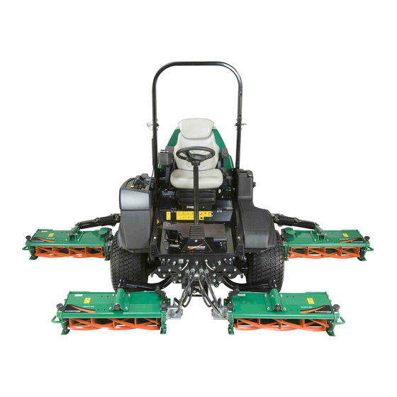
Ransomes MP655, Kubota
Series: LB
Product code: RMP655
WARNING: If incorrectly used this machine can cause severe injury. Those who use and maintain this machine
must be trained in its proper use, warned of its dangers and must read the entire manual before attempting to set
up, operate, adjust or service the machine.
®
V2403-CR-TE4, 4WD with ROPS
WARNING
GB
RJL 100 September 2015
United
Kingdom
25090G-GB (Rev.0)
Advertisement
Table of Contents

Related Manuals for Ransomes RMP655


Summary of Contents for Ransomes RMP655
- Page 1 Ransomes MP655, Kubota V2403-CR-TE4, 4WD with ROPS Series: LB Product code: RMP655 WARNING WARNING: If incorrectly used this machine can cause severe injury. Those who use and maintain this machine must be trained in its proper use, warned of its dangers and must read the entire manual before attempting to set up, operate, adjust or service the machine.
-
Page 2: Table Of Contents
................. 39 RACTION EDAL ..............39 TEERING ONTROL ....................39 ................... 40 OWER UTLET ..........40 IGHT SIDE RMREST ............41 ARKING RAKE ELEASE ALVE ..................41 ALVE ) ..............41 IGHTING PTIONAL © 2015, Ransomes Jacobsen Limited. All Rights Reserved... -
Page 3: Introduction 2
When the machine is at its end of life, there are guidelines in this manual for the removal of the machine from use. Use only Ransomes Jacobsen Genuine spare parts to meet the machine type approval regulations specified by the European Union. -
Page 4: Product Identification
2 INTRODUCTION PRODUCT IDENTIFICATION ___________________________________________ Maximum front axle load in Kg (for all machines being driven on the highway) West Road Ransomes Europark Ipswich IP3 9TT Weight-Mass in Kg England Maximum rear axle load in Kg (for all machines being driven... - Page 5 The engine serial number is also found on the engine block. 1 9 4 2 6 - 8 7 9 0 3 ROPS Serial number plate Weight of ROPS West Road Ransomes Europark Date Code Ipswich IP3 9TT England Standard Used...
-
Page 6: Guidelines For The Disposal O F Scrap
“General discarded materials” area. • Do not burn discarded materials. Change the machinery records to show that the machine is not in operation and is discarded. Supply this serial number to The Ransomes Jacobsen Warranty Department to close their records. en-6... -
Page 7: Parts Manual
INTRODUCTION 2 PARTS MANUAL ______________________________________________________ To meet the standard ISO14001, Ransomes Jacobsen Limited does not send a paper parts manual with every product. To refer to the parts list for this mower you have four options: Website – www.ransomesjacobsen.com. Select the “ONLINE PARTS LOOK-UP” tab. These pages will show the parts list and the line drawings you need to help with the identification of spare parts. - Page 8 2 INTRODUCTION NOTES en-8...
-
Page 9: How To Operate Safely
Manuals in additional languages may be available on the Jacobsen or Ransomes Jacobsen website. Read all of the instructions for this mower carefully. Know the controls and the correct operation of the equipment. -
Page 10: Operation
3 SAFETY 3.1.3 Operation Never operate the engine without enough ventilation or in an enclosed area. The carbon monoxide in the exhaust fumes can increase to dangerous levels. Never carry passengers. Keep other persons or animals away from the mower. Disengage all drives and engage the parking brake before you start the engine. -
Page 11: Rops
Do not weld, drill, change or bend the ROPS. Replace a damaged ROPS. Do not try to correct a damaged ROPS. Do not remove the ROPS from the mower. Ransomes Jacobsen must approve any changes to the ROPS. 3.1.5 Safe Handling of Fuels The fuel and the fuel vapors are flammable. -
Page 12: When You Put The Mower O N A T
Replace worn or damaged parts for safety. Replace damaged or worn decals. Only use parts, accessories and attachments approved by Ransomes Jacobsen. To decrease the fire hazard, remove materials that burn from the engine, muffler, battery tray and fuel tank area. -
Page 13: Important Safety Notes
By following all instructions in this manual, you increase the life of your machine and keep its maximum performance. Adjustments and maintenance must always be done by an approved technician. If additional information or service is needed. Contact your Authorized Ransomes Jacobsen Dealer, who knows the latest methods to service this equipment and can give that service. - Page 14 2006/42/EC sections 3.2.2, seating & 3.4.3, rollover. (ANSI b71.4-2012 section 20.7) Ransomes Jacobsen limited recommends that the owner/user of the machine completes a local risk assessment of the machine to find any conditions that do not follow this rule. e.g. when you drive the machine next to water or on the highway.
- Page 15 SAFETY 3 WARNING Vibration exposure limits Exposure limits are calculated as a combination of the vibration level (magnitude) of the tool and the daily exposure time (trigger time). e.g. a product with 5m/s² vibration can be used up to 2 hours/day to reach the EAV and up to 8 hours/day to reach the ELV.
-
Page 16: Decals
4 DECALS 4.1 SAFETY DECALS _____________________________________________________ 4324674 4153197 19°+ 4321506 en-16... - Page 17 DECALS 4 009034920 Caution, Stay Away From Hot Surfaces. 009034880 Caution, Fan Blade, Do Not Open Or Remove The Safety Shields While The Engine Is In Operation. 009034900 Caution, Drive Belt, Do Not Remove The Safety Shields While The Engine Is In Operation.
-
Page 18: Instruction Decals
4 DECALS INSTRUCTION DECALS ______________________________________________ TOTAL EQUIVIS ZS 46 x 0 ≈ 100 rpm CLASSIFICATION x 2 ≈ 700 rpm CJ-4 x 3 ≈ 1135 rpm 4345686 en-18... - Page 19 DECALS 4 Description 009034770 Guaranteed Sound Power Level 4316826 Mow Selector 4316827 Transport Selector 4164861 Forward / Reverse Traction Pedal 4286422 Hydraulic Fluid 009039870 Jack & Hook Point 4164580 Lubrication Point 4316686 Engine Oil Classification 4345686 Cutting Cylinder Speed Adjust en-19...
-
Page 20: Controls
5 CONTROLS OPERATOR WORKSTATION __________________________________________ 9.11 en-20... -
Page 21: Control Panel
5 CONTROLS CONTROL PANEL ___________________________________________________ Starter Key Switch. Hazard Switch (Optional) Throttle Control Lever. Right hand Unit Lift/Lower Switch. Parking Brake Switch. Centre Unit Lift/Lower Switch. Backlap Switch. Left hand Unit Lift/Lower Switch. Cutter Switch. Cutting Unit engaged LCD. Beacon Switch (Optional). Right hand cutting unit in cutting position 4 WD in reverse direction Switch. -
Page 22: Starter Key Switch
5 CONTROLS 5.2.A STARTER KEY SWITCH _______________________________________________ Turn the starter key to the right to the 'start' position to start the engine. When the engine starts, release the key and allow to return automatically to the 'on' position to run. NOTE. -
Page 23: Cutter Switch
5 CONTROLS 5.2.E CUTTER SWITCH ____________________________________________________ This switch engages cutter rotation. To cut grass, push the switch and move the joysticks forward to lower the cutting units. When engaged the yellow LED on the pod is illuminated. To stop rotation, push the rear of the rocker switch. When lifted out of work or the operator leaves the seat, cylinder rotation is stopped. -
Page 24: Dpf Switch
5 CONTROLS 5.2.J DPF SWITCH ______________________________________________________ With the switch in the center position (default) it allows automatic Active Regen. Operation of the mower is not changed during Active Regen. See 8.15 When the Regen Request light flashes, press and release the front part of the switch to start the Parked Regen cycle. -
Page 25: Lift / Lower Switch ' S
5 CONTROLS 5.2.N, P, RLIFT/LOWER SWITCH’S ____________________________________________ Right Hand Wing cutting unit Front and centre cutting units Left Hand Wing cutting unit To lower the cutting unit move the switch lever forward. To raise the cutting unit move the switch lever rearwards NOTE: If the cutter is engaged when the unit is lowered the green led will illuminate when the unit is below 400mm from the ground. -
Page 26: Visual Display
5 CONTROLS 5.2.Z.1 VISUAL DISPLAY ________________________________________________ The visual display is activated when the ignition is turned on. 5.2.Z.2 STARTUP SCREEN ______________________________________________ When the ignition key is turned to the start position, this screen is shown. The hour meter will show total hours of engine operation. 5.2.Z.3 WARNING/SERVICE SCREEN _____________________________________ After the startup screen the warning screen is shown, the screen is visible for... -
Page 27: The Engine Will Not Start
5 CONTROLS 5.2.Z.6 THE ENGINE WILL NOT START ____________________________________ When the ignition key is turned to the start position this screen is shown. If any of the following flash. • The parking brake is not applied. • The cutter switch is not in the OFF position. •... -
Page 28: Main Menu Select
5 CONTROLS 5.2.Z.10 MAIN MENU SELECT_____________________________________________ Use the button below the to access the main menu. MODE 5.2.Z.11 CLOCK SELECT_________________________________________________ button accepts the option that has the is moved with the up and down to select, date, service, settings or language. -
Page 29: Date Format
5 CONTROLS 5.2.Z.14 DATE FORMAT__________________________________________________ Press the Down button to select the date format (underlined). Press to change the option. Press the button up and down to move between US and EU. Press accepts the option. C l o c k S e t t i n g s Dat e 0 1 / 0 1 / 201 0 Press the button to return to main menu. -
Page 30: Fault Log Detail
5 CONTROLS 5.2.Z.18 FAULT LOG DETAIL _____________________________________________ Select the fault log to be accessed and accept to show the details. These details show the date and time of the fault. F a u l t l o g Press the button to return to previous menu. -
Page 31: Diagnostics
5 CONTROLS 5.2.Z.21 DIAGNOSTICS __________________________________________________ Water Temp [deg C] = 80.5 Fuel Level [pct] = 100 S e r v i c e M e n u D i a g n o s t i c s Sys Voltage [V] = 11.8 F a ul t L o g Wa t e r Te m p [ d e g C ] = 8 0 . -
Page 32: Connector J3
5 CONTROLS 5.2.Z.25 CONNECTOR J3_________________________________________________ This screen shows the status of the J3 connectors Press the left side button to return to I/O diagnostics menu. For pin designations see section 11. Connector J3 J3-1 Traction Pedal 2 [mV] J3-2 Spare Analog 1 [mV] J3-3 Right Joystick [mV] J3-4 Center Joystick [mV] J3-5 Left Joystick [mV]... -
Page 33: Language Menu
5 CONTROLS 5.2.Z.29 LANGUAGE MENU ______________________________________________ Select the language and accept M a i n M e n u C l o c k Se r v i c e Se tti n g s L a n g u a g e 5.2.Z.30 LANGUAGE OPTION_____________________________________________ On the page for the language options, Press the button... -
Page 34: Settings Menu - Measure Units
5 CONTROLS 5.2.Z.1 SETTINGS MENU - MEASURE UNITS _______________________________ Select the measure units and accept S et t ing s Me nu M o d e M e a s u r e U n i t s PI N 5.2.Z.2 MEASURE UNITS________________________________________________ ... -
Page 35: Warning Slope Angle 16
5 CONTROLS 5.2.Z.33 WARNING SLOPE ANGLE 16° _____________________________________ During work if the machine is driven on a slope of 16º the screen will display this warning. This over rides all other information, and will continue until the machine has been driven to an area with a slope of less than 16º ... -
Page 36: Warning Oil-Pressure Fault
5 CONTROLS NOTICE The number in the top right of the screen indicates the total number of current faults recorded. If more than one fault, it will cycle all current faults. 5.2.Z.36 WARNING OIL-PRESSURE FAULT __________________________________ When this screen is shown, the engine oil pressure has decreased below the normal level. -
Page 37: Warning Battery Fault
5 CONTROLS 5.2.Z.40 WARNING BATTERY FAULT _______________________________________ When this screen is shown, the battery is not charging or there is a charge circuit fault. Press the button below the to confirm the fault. 5.2.Z.41 WARNING CHARGE FILTER BLOCKED _____________________________ When this screen is shown, the hydraulic-charge filter is blocked and needs replacing. -
Page 38: Warning Solenoid Fault
5 CONTROLS 5.2.Z.44 WARNING SOLENOID FAULT _____________________________________ When this screen is shown, there is a hydraulic circuit solenoid fault. Go to i/o diagnostics for solenoid identification. Press the button below the to confirm the fault. FAULT SOLENOID 5.2.Z.45 WARNING (TST) TILT SENSOR TECHNOLOGY FAULT ________________ When this screen is shown, there is a fault with the TST. -
Page 39: Cutting Cylinder Variable Speedc
Rotate the hand wheel counter clockwise to increase cylinder speed, x 3 ≈ 1135 rpm clockwise to decrease cylinder speed. All adjusters should be adjusted the West Road Ransomes Europark Ipswich IP3 9TT England same amount. Cylinders should be operated at approximately 1150 rpm in normal conditions. -
Page 40: Power Outlet
5 CONTROLS 5 7. POWER OUTLET ____________________________________________________ The Auxiliary Power Outlet is on the control panel next to the ignition switch. It is for use with mobile phone chargers and accessories. Automotive 12 Volt, 10-Amp Power Outlet 5 8. SEAT RIGHT-SIDE ARMREST AND POD _________________________________ The right-side armrest of the seat has an extension which carries the control pod. -
Page 41: Parking Brake Release Valve
5 CONTROLS 5 9. PARKING BRAKE RELEASE VALVE ____________________________________ The Parking Brake Release Valve is situated under the foot plate, on the right hand side of chassis plate. The Parking Brake Release Valve is used to release the parking brake when the engine is not in operation The Parking brake is released with the handwheel (A) turn completely to the right side, after you release lock wheel (B). - Page 42 5 CONTROLS NOTES en-42...
-
Page 43: Operation Daily Inspection
OPERATION 6 6.1 DAILY INSPECTION ____________________________________________________ CAUTION The inspection must be done each day when the engine is turned off and all fluids are cold. lower the cutter equipment to the ground, engage the parking brake, stop the engine and remove the ignition key. -
Page 44: Operator Presence And Safety Interlock
6 OPERATION OPERATOR PRESENCE AND SAFETY INTERLOCK SYSTEM _________________ The Operator Presence And Safety Interlock System will not allow the engine to start unless the operator is sitting in the seat, the parking brake is engaged, the cutter switch is disengaged and the traction pedal is in neutral. -
Page 45: Procedure For Operation
OPERATION 6 PROCEDURE FOR OPERATION__________________________________________ You must not start the engine without the operator in the seat on the tractor. CAUTION To prevent injury, always wear the safety glasses, leather work shoes or boots, a hard hat and ear protection. Do not operate the tractor and attachments with loose or damaged components. -
Page 46: To Fit The Cutting Units To The Machine
6 OPERATION TO FIT THE CUTTING UNITS TO THE MACHINE ____________________________ NOTE For height of cut adjustments see section 7.2 and 7.3 Cutting Unit Mounting Magna 250 and Meteor Front and wing units With the lift arms (A) in the lower position align cutting unit mounting bracket (B) with shaft fitted with spacer (C). -
Page 47: Operation Of The Machine
OPERATION 6 OPERATION OF THE MACHINE __________________________________________ Check the machine, look for worn, damaged or loose parts. Check the machine for fuel and oil leaks. Make sure that all connections are tight. Make sure that all hoses and tubes are in good condition. Check the fuel level, radiator coolant level, crankcase oil level and air cleaner is clean. -
Page 48: How To Drive
6 OPERATION HOW TO DRIVE _______________________________________________________ • Set the throttle to maximum engine speed. • Release the parking brake before you move in a forward or reverse direction. • Forward - Carefully press the top of the Traction pedal to engage forward drive. •... -
Page 49: T O Removea Blockage From Cutting Units
NOTE Make sure correctly selected PPE is worn before you clear the obstruction. Use the Ransomes Jacobsen “Cutting Unit Tool” part number 4184540, see below or stout stick, put into the cutting cylinder between the blades. Rotate the cylinder with either the “Cutting Unit Tool” or “Stout Stick” until the obstruction has been removed. -
Page 50: Backlapping
• Backlapping must only be done by approved personnel. • Ransomes Jacobsen recommend that grinding paste is only applied to the cylinder when it is stationery, the engine is off and the parking brake applied. • When applying grinding paste the cylinder must only be rotated by appropriately sized piece of wood and not by hand. -
Page 51: Transporting On A Trailer
OPERATION 6 6.12 TRANSPORTING ON A TRAILER _________________________________________ The machine is fitted with tie-down loops front and rear. Always tie down the machine securely to the trailer. Always follow any recommendations for maximum trailer weights given in your towing vehicles handbook. IMPORTANT Use the chart in the specification section 12.2 to calculate the total weight of your machine configuration. -
Page 52: Mowing On Slopes
6 OPERATION 6.14 MOWING ON SLOPES __________________________________________________ The mower is designed for good traction and stability in normal conditions for operation. On wet grass slopes use caution, as wet grass decreases traction and steering control. WARNING 15° Maximum To decrease the possible cause of overturning. The safest method for operation on slopes and A = Maximum Allowed Slope terraces is. - Page 53 Comply With The Machinery Directive 2006/ 42/EC Sections 3.2.2, Seating & 3.4.3, Rollover ####### Ransomes Jacobsen Limited Recommends That A Local Risk Assessment Is Completed By The Owner/user Of The Machine To Determine The Risks Associated With Working On Slopes.
- Page 54 6 OPERATION SLOPE CALCULATION CHART Use Either of these columns but not both The result of what you are measuring Height ‘C’ in inches Height ‘C’ in millime- Slope Angle ‘D’ Slope Angle ‘D’ measured with a 1 yard ters measured with a 1 measured in measured in horizontal edge ‘A’...
- Page 55 OPERATION 6 NOTES en-55...
-
Page 56: Adjustments
Always use the jack stands. A qualified technician must always do adjustments and maintenance. If the correct adjustments can not be made, contact your Ransomes Jacobsen Dealer. Inspect the equipment according to the maintenance schedule and keep complete records. -
Page 57: Cutting Unit Height Of Cut Adjustment
ADJUSTMENTS 7 CUTTING UNIT HEIGHT OF CUT ADJUSTMENT ____________________________ TO ADJUST SPANNER TYPE: Turn adjuster (A) at the rear of the unit clockwise to reduce the height of cut, or anticlockwise to increase the height of cut. The grooves (B) are used as an rough indicator for setting the roll parallel. -
Page 58: Cutting Cylinder To Bottom Blade Adjustment
7 ADJUSTMENTS CUTTING CYLINDER TO BOTTOM BLADE ADJUSTMENT ____________________ To check that the cutting cylinder is set to the bottom blade correctly, hold a piece of thin paper between the edge of the blade and the spiral cutters and turn the cylinder manually. The rubber cap on the non drive end bearing housing can be removed and the hexagon end of the shaft turned using a spanner. -
Page 59: Cutting Cylinder Bearings
ADJUSTMENTS 7 CUTTING CYLINDER BEARINGS ________________________________________ The cutting cylinder bearings are self adjusting taper roller bearings and require no adjustments. FRONT AND REAR ROLL BEARINGS _____________________________________ The roll bearings are self adjusting taper roller bearings and require no adjustment GRASS DEFLECTOR __________________________________________________ The grass deflector can be positioned by hand as it is ‘friction clamped’... -
Page 60: General Instructions For Grammer Seats
7 ADJUSTMENTS GENERAL INSTRUCTIONS FOR GRAMMER SEATS ________________________ • After removal of the backrest cover, hold the backrest frame in position with a support before the backrest adjuster is operated. If you do not lock the frame in position safely, the backrest frame can move forward suddenly and can cause injury. -
Page 61: Seat (Grammer Msg85)
ADJUSTMENTS 7 SEAT (GRAMMER MSG85) ____________________________________________ To get a good seat position to operate the machine you need to adjust the leg reach, the backrest angle and the operator weight. A. FRONT AND REAR ADJUSTMENT To Adjust: The adjusting lever (A) is on the right side of the seat. Lift the lever and the seat can move backward and forward. When the seat is in the correct position, release the lever to put the seat into one of the preset positions. -
Page 62: Air Suspension Seat (Grammer Msg75 -521)
7 ADJUSTMENTS 7.10 AIR SUSPENSION SEAT (GRAMMER MSG75 -521) ________________________ 7.10.1 WEIGHT ADJUSTMENT _______________________________________________ To adjust the seat for the driver weight, pull or press the lever for the seat weight adjustment with the driver on the seat. When the arrow is in the center clear area of the view window, the driver weight is adjusted correctly. -
Page 63: Lumbar Support (Option)
ADJUSTMENTS 7 7.10.4 LUMBAR SUPPORT (OPTION) _________________________________________ The lumbar support improves the quality of the seat and increases the performance of the driver. To adjust the curve in the upper part of the backrest cushion, rotate the adjustment knob to the top. To adjust the curve in the lower part of the backrest cushion, rotate the adjustment knob to the bottom. -
Page 64: Maintenance
7 ADJUSTMENTS 7.10.8 MAINTENANCE ______________________________________________________ If there is dirt in the seat, the seat can operate incorrectly. Make sure that the seat is kept clean. Do not remove the seat for cleaning. CAUTION: Be careful with the backrest - it can move forward and cause injury. Lock the backrest in position when you clean the backrest cushion. - Page 65 ADJUSTMENTS 7 NOTES en-65...
-
Page 66: Maintenance And Lubrication
8 MAINTENANCE AND LUBRICATION MAINTENANCE AND LUBRICATION CHARTS ______________________________ MACHINE SERVICE INTERVAL CHART Interval Item Section First 50 hours Change the Hydraulic Charge Filter Element Each day Check Safety Interlock System 10 hours Check the Hydraulic Fluid Level ... - Page 67 MAINTENANCE AND LUBRICATION 8 en-67...
- Page 68 8 MAINTENANCE AND LUBRICATION ENGINE SERVICE INTERVAL CHART Interval Item Section Daily Check Engine Oil Level. 10 hours Check Fuel Level. Check Coolant Level. Check Fan Belt Tension. Check Fuel Pipes and Clamps. Every 50 hours ...
- Page 69 MAINTENANCE AND LUBRICATION 8 Interval Item Section Replace Oil Separator Related Rubber Piping. Replace DPF Related Rubber Piping. Replace Intake Air Line and Suction Air Pressure takeout Rubber Piping. Replace Boost Sensor Pressure Rubber Piping. Replace EGR Cooler Rubber Piping.
-
Page 70: General Precautions
• Refer to the Engine manual for specified maintenance intervals. If the injection pump, injectors or the fuel system need service, contact your Ransomes Jacobsen Dealer. NOTICE The mower operates and cuts correctly at the preset governor setting. Do not change the engine governor setting or over speed the engine. -
Page 71: Engine Lubrication
MAINTENANCE AND LUBRICATION 8 ENGINE LUBRICATION _________________________________________________ Check Engine Oil Level Check the engine oil level before you start or at least five minutes after you stop the engine. Park the machine on level ground, remove the dipstick (A), clean with a cloth and replace in position. -
Page 72: Engine Coolant
Replace the clamps and hoses (see maintenance chart). Have your Ransomes Jacobsen Dealer check the cooling system if you need to add coolant more than one time a month or you add more than a litre of coolant at a time. - Page 73 MAINTENANCE AND LUBRICATION 8 Check The Engine Coolant Level The level of coolant in a cold expansion tank must be between the indicators. If you need to fill the tank, remove the plastic cap and fill with the correct anti-freeze mixture (see section 8.1). Replace the plastic cap.
-
Page 74: Hydraulic System
8 MAINTENANCE AND LUBRICATION HYDRAULIC SYSTEM __________________________________________________ To fill the hydraulic tank with hydraulic oil. Remove the filler cap (A) Using a 25 micron filter fill the tank with the correct hydraulic oil to the correct level. Replace the hydraulic tank cap (A) CAUTION The Hydraulic Oil Can Damage Your Skin. -
Page 75: Fuel System
MAINTENANCE AND LUBRICATION 8 FUEL SYSTEM ________________________________________________________ Use Diesel to B.S. EN590 or ASTM D975 (Ultra Low Sulfur) Water Separator If the water is not removed from the fuel, damage to the fuel-injection system can occur. When the fuel filter light on the filter light module is illuminated or at service interval, drain the water from the water separator. -
Page 76: Air Cleaner
8 MAINTENANCE AND LUBRICATION AIR CLEANER ________________________________________________________ Check the service indicator each day. If the red band become visible in the window, replace the filter elements. Do not remove the elements to inspect or clean. Removal of the filter that is not necessary increases the risk of dust and other particles to enter the engine. -
Page 77: Battery
MAINTENANCE AND LUBRICATION 8 8.10 BATTERY ____________________________________________________________ Before you service the battery, make sure the ignition switch is in the OFF position and the key is removed. CAUTION When you service the battery, always use the tools with insulation, wear protective glasses and protective clothing. -
Page 78: Charge The Battery
8 MAINTENANCE AND LUBRICATION 8.11 CHARGE THE BATTERY _____________________________________________________ WARNING Charge the battery in an area with good airflow. The battery can release hydrogen gas that is explosive. To prevent an explosion, keep any device that can cause sparks or flames away from the battery. -
Page 79: Diesel Particulate Filter
MAINTENANCE AND LUBRICATION 8 8.13 DIESEL PARTICULATE FILTER __________________________________________ During the operation of the mower, the level of particle material will increase in the Diesel Particulate Filter (DPF) system. The periodic Regen of the DPF system is needed to remove particle material. During an Active or Parked Regen, the engine will use more fuel. -
Page 80: Hydraulic Hoses
8 MAINTENANCE AND LUBRICATION 8.14 HYDRAULIC HOSES _________________________________________________________ WARNING To prevent injury from the hot, high pressure oil, never use your hands to check for oil leaks. Use the paper or cardboard to find leaks. The hydraulic fluid pressure can have enough force to enter your skin. If hydraulic fluid has entered your skin, a doctor must remove the hydraulic fluid surgically within a few hours or gangrene can occur. -
Page 81: Tyres
MAINTENANCE AND LUBRICATION 8 8.15 TYRES ______________________________________________________________ Keep the tyres correctly inflated to increase tyre life. Inspect the tread wear. Check the tyre pressure each day, while the tyres are cool. Use an accurate low-pressure tyre gauge. Keep tyres inflated at the correct pressure (see section 8.1) CAUTION DO NOT try to put a tyre on a rim unless you have the correct training, tools and experience. -
Page 82: Folding Rops
This instruction is given to meet: The machinery directive, 2006/42/EC sections 3.2.2, seating & 3.4.3, rollover. Ransomes Jacobsen Limited. recommend that the owner operator of the machine complete a local risk assessment on the machine to find any conditions that do not follow this rule. -
Page 83: Care And Cleaning
Clean all plastic or rubber parts with a weak soap solution or use commercially available rubber cleaners. To keep the original high polish of the plastic parts, wax with a good grade of one-step cleaner wax. Repair damaged metal surfaces and use Ransomes Jacobsen touch-up paint. Apply wax to the equipment for maximum paint protection. -
Page 84: Mower Storage
8 MAINTENANCE AND LUBRICATION 8.19 MOWER STORAGE ____________________________________________________ General • Clean the mower and lubricate. Repair and paint damaged or open metal. • Inspect the mower, tighten all hardware, replace worn or damaged components. • Drain and fill the radiator. •... -
Page 85: Lubrication Of Cutting Units And Lift Arms
MAINTENANCE AND LUBRICATION 8 8.20 LUBRICATION OF CUTTING UNITS AND LIFT ARMS ________________________ Wing Pivot Arm (A) Front Pivot Arm (B) Centre Pivot Arm (C) en-85... - Page 86 8 MAINTENANCE AND LUBRICATION Cutting Unit Mounting (D) Bearing Housings (E) Rolls (F) en-86...
- Page 87 MAINTENANCE AND LUBRICATION 8 NOTES en-87...
-
Page 88: Problem Solving
PROBLEM SOLVING ENGINE PROBLEM DIAGNOSTICS ___________________________________ The Engine is difficult to start The Engine stops Cause Action Cause Action Check the fuel tank and fuel filter. Check the fuel tank and fill with fuel. There is no Fuel The fuel is thick and does Remove any contamination from the Check the fuel system for air leaks. - Page 89 PROBLEM SOLVING 9 Engine Temperature above Safe Maximum. Cause Action Engine oil low. Check oil level. Fill to specified level. The fan belt is broken or Change the belt or adjust the belt has defects. tension. Coolant low. Fill to the specified level. The Anti-freeze solution Add clean water only or change to is too strong.
-
Page 90: Quality Of Cut
10 QUALITY OF CUT 10.1 QUALITY OF CUT TROUBLESHOOTING ___________________________________ It is recommended that a “test cut” be performed to Before performing a “test cut” to diagnose cut appear- evaluate the mower’s performance before beginning ance and mower performance, the following items repairs. -
Page 91: Step Cutting
QUALITY OF CUT 10 10.3 STEP CUTTING ________________________________________________________ Step cutting occurs when grass is cut taller on one side of a cutting unit than the other or on one side of mower to the other. This is usually caused by mechanical wear or an incorrect roller adjustment. -
Page 92: Scalping
10 QUALITY OF CUT 10.4 SCALPING ___________________________________________________________ Scalping is a condition in which areas of grass are cut noticeably shorter than the surrounding areas, resulting in a light green or even brown patch. This is usually caused by an excessively low height-of- cut (HOC) setting and/or uneven turf. -
Page 93: Stragglers
QUALITY OF CUT 10 10.5 STRAGGLERS ________________________________________________________ Stragglers are scattered blades of uncut or poorly cut grass. TN0223 NOTE: Arrow indicates direction of travel. Probable Cause Remedy Dull cutting blades). Sharpen or replace blade. Mowing (ground) speed is too fast. Reduce mowing (ground) speed. -
Page 94: Streaks
10 QUALITY OF CUT 10.6 STREAKS ____________________________________________________________ A streak is a line of uncut grass. This is usually caused by a damaged blade. TN0224 NOTE: Arrow indicates direction of travel. Probable Cause Remedy Damaged blade(s). Replace blade(s). Turning too aggressively. Cutting units don’t overlap Turn less aggressively to allow cutting units to over- during turns or on side hills. -
Page 95: Windrowing
QUALITY OF CUT 10 10.7 WINDROWING ________________________________________________________ Windrowing is the deposit of clippings concentrated at one end of cutting unit(s) or between two cutting units, forming a line in the direction of travel. TN0225 NOTE: Arrow indicates direction of travel. Probable Cause Remedy Grass is too tall. -
Page 96: Mismatched Cutting Units
10 QUALITY OF CUT 10.8 MISMATCHED CUTTING UNITS __________________________________________ Mismatched cutting units is a pattern of varying cut- ting heights, resulting in a stepped cut appearance, usually due to mismatched HOC (height-of-cut) ad- justment from one cutting unit to another. TN1278 NOTE: Arrow indicates direction of travel. - Page 97 QUALITY OF CUT 10 NOTES en-97...
-
Page 98: Fuses And Relays
11 FUSES, RELAYS AND CONTROLLER 11.1 FUSE AND RELAY/COMPONENT IDENTIFICATION _________________________ en-98... - Page 99 FUSES, RELAYS AND CONTROLLER 11 FUSES FUSE HOLDER 1 Fuse Rating Protected Circuits 7.5A EM Positive to Fuel Pump Key Switch to Beacon And Horn 7.5A Key Switch to Proximity Switches and Pressure Switches Key Switch to Accessory Sockets FUSE HOLDER 2 Fuse Rating Protected Circuits...
- Page 100 11 FUSES, RELAYS AND CONTROLLER en-100...
- Page 101 FUSES, RELAYS AND CONTROLLER 11 FUSE HOLDER 4 Fuse Rating Protected Circuits Battery Positive Distribution Box to Machine Control Unit Positive Splice A Battery Positive Distribution Box to Machine Control Unit Positive Splice B Battery Positive Distribution Box to Engine Master Relay Splice to Start Circuit Signal I/P from M Positive Splice to O/P to Engine Control Unit 7.5A...
- Page 102 11 FUSES, RELAYS AND CONTROLLER NOTES en-102...
-
Page 103: Specifications 12
SPECIFICATIONS 12 12.1 ENGINE SPECIFICATION _______________________________________________ Model: V2403-CR-TE4 Type: Vertical, water-cooled, 4-cycle diesel engine Number of Cylinders Bore and Stroke 87mm x 102.4mm (3.43 in. x 4.04 in.) Total Displacement 2.434 litres (148.53 cu.in.) Combustion Type Direct Injection SAE Net Intermittent kW / rpm 48.6 kW @ 2700 rpm H.P. -
Page 104: Dimensions & Weights
12 SPECIFICATIONS 12.2 DIMENSIONS & WEIGHTS _______________________________________________ A Width Of Cut: 348 cm 137 In. B Overall Width: 373 cm 146.8 In. Maximum Width Transport With Floating Head Sport 200 At 25 mm Height 199.8 cm 78.7 In. Of Cut: D Maximum Height With ROPS Frame Up: 210cm 82.7 In. - Page 105 SPECIFICATIONS 12 en-105...
-
Page 106: Machine Specification
12 SPECIFICATIONS 12.3 MACHINE SPECIFICATION _____________________________________________ Frame construction: Heavy duty steel chassis with box section frame rails. Cutting Unit Drive: Five individual hydraulic motors with self lubricating integral bearings. Transmission: Hydrostatic closed loop parallel cross series SureTrac system. Variable displacement piston pump. -
Page 107: Vibration
SPECIFICATIONS 12 12.4 VIBRATION__________________________________________________________ The machine was tested for hand and arm vibration levels. The operator was in the normal position to drive the vehicle, with two hands on the steering mechanism. The engine was in operation and the cutting device was in rotation. -
Page 108: Noise
12 SPECIFICATIONS 12.5 NOISE ______________________________________________________________ When the machine was tested for sound pressure (Operator Ear). The Machinery Safety Directive 2006/42/EC Exposure Of Workers To The Risks Arising From Physical Agents (Noise) Directive 2003/10/EC By compliance to: The Lawnmower Standard BS EN ISO 5395:2013 Sound Pressure Standard EN ISO 3746: 2010 Measured Sound Pressure 87.4 dB(A) ±... -
Page 109: Cutting Unit Specification
SPECIFICATIONS 12 12.7 CUTTING UNIT SPECIFICATION_________________________________________ Magna 250 Sport 200 Fixed Sport 200 Floating Verticut Construction Heavy duty welded pressed steel construction Reel Length 762mm 762mm 762mm 762mm Number of Knives 4 / 6 / 8 4 / 6 / 8 4 / 6 / 8 / 11 Reel Diameter 254mm... -
Page 110: Recommended Lubricants
12 SPECIFICATIONS 12.9 RECOMMENDED LUBRICANTS _________________________________________ Grease: Shell Darina R2 lithium grease or equivalent. 12.10 ACCESSORIES_______________________________________________________ Air Suspension Seat (MSG75) Kit Kit number LMAC560 Lights and mirror Kit Kit number LMAC556 Beacon Kit Kit number LMAC531 Armaturf Tyre Kit Kit number WL065 Bat (for clearing blockages) 4184540 en-110... -
Page 111: Certificates Of Conformity
SPECIFICATIONS 12 12.11 CERTIFICATES OF CONFORMITY _______________________________________ Ransomes Jacobsen Limited West Road, Ransomes Europark, Ipswich, England, IP3 9TT RMP655 RMP655C Ransomes MP655 Ride on Reel Mower LB000301 - LB999999 TA000301 - TA999999 V2403-CR-TE4 48.6 kW @ 2700 RPM 350 cm... - Page 112 Flail Mowers) ANSI B71.4-2012 Ransomes Jacobsen Limited West Road, Ransomes Europark, Ipswich, England, IP3 9TT 1st May 2015 Signature of the person empowered to draw up the declaration on behalf of the manufacturer, holds the technical documentation and is authorised to compile the technical file, and who is established in the Community.
- Page 113 SPECIFICATIONS 12 ERKLÆRING Ransomes Jacobsen Limited West Road, Ransomes Europark, Ipswich, England, IP3 9TT Product Code Serial Number Description LMAC403-L HJ100301 - HJ199999 MAGNA 250 x 4K FX-RHD (HAND-SPANNER) - FRONT LH UNIT HK200301 - HK299999 LMAC403-R MAGNA 250 x 4K FX-LHD (HAND-SPANNER) - FRONT RH UNIT...
- Page 114 La quasi-macchina non deve essere messa in servizio finché la macchina finale in cui deve essere incorporata non è stata dichiarata conforme, nel caso, alle disposizioni della Direttiva RMP653 / RMP653C 2006/42/CE. Excluding Meteor Units Ransomes RMP493 / RMP493C LGNN344 / LGNN345 Dalinai užbaigto mechanizmo negalima paleisti kol kiti mechanizmai, kurie dar bus prijungti, nebus patvirtinti kaip atitinkantys 2006/42/EC Direktyvos reikalavimus. 2006/42/KE.
- Page 115 SPECIFICATIONS 12 NOTES en-115...
-
Page 116: Warranty
13 GUARANTEE 13.1 GUARANTEE _________________________________________________________ WARRANTY Warranty is subject to specific terms and conditions, e.g. wearing parts, unapproved modifications, etc. are not included. For a full set of warranty conditions, contact your local dealer or distributor. SERVICE A network of authorised Sales and Service dealers has been established and these details are available from your supplier. - Page 118 Europe & Rest of The World Except North & South America Ransomes Jacobsen Limited West Road, Ransomes Europark, Ipswich, IP3 9TT English Company Registration No. 1070731 www.ransomesjacobsen.com North & South America Jacobsen, A Textron Company 11108 Quality Drive, Charlotte, NC 28273, USA...