Table of Contents
Advertisement
Advertisement
Table of Contents

Related Manuals for Videonics MXPro


Summary of Contents for Videonics MXPro
- Page 1 MXPro User Guide...
- Page 2 STATEMENT OF WARRANTY Videonics, Inc. warrants this product against defects in materials or workmanship as follows: For a period of TWO years from the date of purchase, Vide- onics Inc. will repair or replace the unit, at our option, with- out charge for parts or labor.
-
Page 3: Declaration Of Conformity
Campbell, CA 95008, USA Videonics GmbH Industriestrasse 2 90765 Furth/Bay, Germany MX-3000 PAL I, the undersinged, hereby declare that the equipment specified above conforms to the above directive(s) and standard(s). (Signature) Parminder Gillon (Full Name) Test Engineer (Position) Videonics Video Mixer MXPro 1998... - Page 4 Notes ®...
-
Page 5: Table Of Contents
• 19 Number of Monitors Understanding MXPro Connectors • • 22 Power Connector Cables and Adapters • Installation Examples • Correlating Input Sources to MXPro Jacks • 25 Using Headphones • 25 VCR Selector Switches • 25 General Notes Live Broadcast Configuration Post Production Configuration Using a Microphone with MXPro •... - Page 6 Videonics MXPro User Guide Input Effects Input Effects Menu • Special Key Combinations Using Input Effects • B&W • B&W Neg • Posterize • Flip Horizontal • Mosaic • Color Correct • Color Neg • Chroma Key • Flip Vertical •...
- Page 7 Security Monitoring • Using a GPI Device • Instructions for Building a GPI Trigger Using a GPI Trigger Device Calibrating the T-BAR • Resetting MXPro Factory Defaults • APPENDIXES & BACK MATTER • 123 • 125 • 125 • 127 •...
- Page 8 Videonics MXPro User Guide LIST of TABLES Table 1 User Guide Contents Table 2 Videonics Contacts Table 3 Default Colors and Numbers Table 4 Border Styles (Defaults) Table 5 Keys for Changing Border Attributes Table 6 MX-1 Compatibility Hot Keys...
-
Page 9: Introduction
W elcome to MXPro , and thank you for buying Videonics products. This chapter contains: • Brief descriptions of major MXPro features • Typical uses for the MXPro • How to contact Videonics • An inventory of package contents •... -
Page 10: Major Features
Chapter 1 AJOR EATURES MXPro contains features found on most video mixers. In addition, it contains the spe- cial features described in this section. Superb Video Quality — To ensure highest video quality, MXPro uses 10-bit (4:2:2) video technology for Y/C applications, and 8-bit 4:2:2 for Composite applications. -
Page 11: Common Uses For Mxpro
Its digital effects (such as picture freeze, posterization, and zooms) give added life to productions. You can use MXPro with a titler to mix and superimpose titles. Time Base Correction improves the picture (especially when making multiple-generation copies) by removing the jitter common to most VCR’s. -
Page 12: Mxpro Package Contents
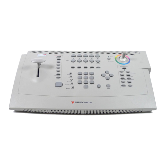
Chapter 1 Videonics MX-Pro User Guide ACKAGE ONTENTS The MXPro package contains the items shown below. Check your package against the illustration. If anything is missing, contact the dealer where you purchased MXPro for the necessary replacements. MXPro Unit Power Adapter and Cord... -
Page 13: About This User Guide
Description Basic overview of MXPro features, description of package contents, description of manual, and so forth. Brief steps to setting up MXPro with your equipment. Provided for people quite familiar with connecting video equipment. Instructions for setting up MXPro to work with your video equipment. - Page 14 Videonics MX-Pro User Guide Description Complete list of transitions available with MXPro, along with their assigned code numbers and descriptions. Explains the time-base corrector feature built into MXPro. Discusses issues concerning the level of quality in videos —...
- Page 15 Introduction About this User Guide MXPro Buttons When referencing the various buttons (or, keys) and other controls on the MXPro key- board, they appear in uppercase, boldface characters. For example, the keyboard con- tains the PLAY button and T-BAR .
-
Page 16: Contacting Videonics
Chapter 1 ONTACTING IDEONICS Videonics provides technical and general support for all of its products. The following table provides information for contacting us with your suggestions, questions, and problems. Table 2: Videonics Contacts Department Corporate Headquarters Main Phone Number Main Fax Number Product Information Information via E-Mail Technical Support... -
Page 17: Quick Start
Users , for helpful information in setting up your MXPro. Skim the instructions in this chapter. If you have any questions about any of the steps, turn to Chapter 3, Installing MXPro , and follow the detailed instructions for setting up your equipment. -
Page 18: Quick Start Steps
MXPro this fact. See “Using the Route Function” below after completing the following steps. ¨ Connect a VCR’s VIDEO IN and AUDIO IN jacks to the OUT jacks on the MXPro rear panel. This is the device where you record the program. -
Page 19: The Preview Screen
Transitions Menu Note MXPro displays small previews of the sources you have attached. The images are scaled down both in size and frame rate and, therefore, don’t play as smoothly as they would in a single-source video monitor image. This does not affect the quality of the video going to the output —... -
Page 20: Running The Demo
If you connect S-Video (Y/C) devices to the IN 1, IN 2, IN3, and/or IN 4 jacks, re-routing is not necessary. Go on to the next section, “Running the Demo”. Otherwise: ¨ After starting MXPro with all devices connected and turned on, press ROUTE to dis- play the Route screen. This display... -
Page 21: Cutting Between Sources
Borders and Solid Color Backgrounds ¨ Press CUT/COLOR. MXPro highlights the speaker, headphone, or color block above the channel indica- tor, but does not show the channel letter. The Output monitor shows a solid color screen. -
Page 22: Setting Up A Transition
Here’s how to transition from source A to source B using a horizontal wipe. ¨ Press CUT/A to set A as the CURRENT source. MXPro shows a steadily glowing light below the CUT button you press. -
Page 23: Using Cut Transitions
¨ Select Transitions in the following ways: ARROW keys – Simply use the arrow keys to highlight the desired transition. NUMBER keys – MXPro assigns a unique number to every transition. The number appears below the transition icon on the PREVIEW screen (in the following exam- ple, the checkerboard transition is number 29). -
Page 24: Using Transition Categories
“tailor” the content of the USER category to your specific needs and preferences. You’ll learn more about this in later chapters. Other Features Refer to the rest of this User Guide to learn about the many additional MXPro features, including: ¨ Using the DISPLAY button to change the content of the Preview screen. -
Page 25: Installing Mxpro
T his chapter explains how to install (or, set up) MXPro to use with other equipment. Major topics include: • Understanding Sources and Output • Understanding Preview and Program monitors • Understanding the MXPro connectors • Identifying Cables and Adapters you might need •... -
Page 26: Sources And Output
This signal is often a mix of signals coming into MXPro from one or more of the sources. The output device might be a VCR with an optional monitor attached, or it might be a live broadcast. -
Page 27: Preview And Program Monitors
CAUTION The Preview monitor must be a Composite device. Do not attempt to connect any other type of monitor to the PREVIEW OUT jack on the MXPro rear panel. Program Monitor The Program monitor shows the production exactly as recorded on the output device or displayed in a live video environment. -
Page 28: Understanding Mxpro Connectors
MXPro’s rear panel. See “Cables and Adapters” on page 23. Remove MXPro from its package and set it so you can see the rear panel. Refer to the panel and the illustration on page 21 while reading this section. - Page 29 MXPro Rear Panel POWER POWER VIDEO IN (Y/C) VIDEO VIDEO IN (Y/C) VIDEO IN S-Video Composite AUDIO DIGITAL VIDEO IN (FUTURE UPGRADE) AUDIO IN Left and Right OUT Y/C AUDIO OUT S-Video Left and Right PREVIEW OUT AUDIO OUT (Y/C)
-
Page 30: Power Connector
Connect the Power Adapter Plug on the Transformer cord into the Power connec- tor on the MXPro rear panel. Turn the MXPro Power Switch (located on the right side of the unit) to the ON position. Videonics MX-Pro User Guide... -
Page 31: Cables And Adapters
To connect video devices to MXPro you need specific types of cables. You might also need one or more adapters, depending on your equipment. Look closely at the jacks on the MXPro rear panel and note that they accept RCA Com- posite or S-Video connectors. -
Page 32: Installation Examples
Chapter 3 Audio Connectors To connect a stereophonic audio device to MXPro, you need two separate audio cables — one for the Left channel and one for the Right. NSTALLATION XAMPLES This section shows examples of two common MXPro configurations, but does not describe every possibility. -
Page 33: Correlating Input Sources To Mxpro Jacks
As stated above, MXPro designates your input sources as A, B, C, and D. However, if IMPORTANT you examine the jacks on the MXPro rear panel you’ll see they are labeled 1, 2, 3, and INFORMATION 4. Initially, there is a direct correlation between the letter and number designations: jack 1 corresponds to source A, jack 2 corresponds to source B, jack 3 to source C, and jack 4 to source D. -
Page 34: Live Broadcast Configuration
Use the Route function (see page 77) to make sure your devices are directed to the cor- rect MXPro channels. Connect the VIDEO OUT from Camera 1 to VIDEO IN 1 on the MXPro rear panel. Connect the AUDIO OUTs from Camera 1 to AUDIO IN 1 on the rear panel. - Page 35 Live Broadcast Configuration POWER VIDEO IN (Y/C) VIDEO AUDIO DIGITAL VIDEO IN (FUTURE UPGRADE) Program Monitor Preview Monitor PREVIEW OUT AUDIO OUT CONTROL (Y/C) (GPI)
-
Page 36: Post Production Configuration
Use the Route function (see page 77) to make sure your devices are directed to the cor- rect MXPro channels. Connect the VIDEO OUT from VTR 1 to VIDEO IN 1 on the MXPro rear panel. Connect the AUDIO OUTs from VTR 1 to AUDIO IN 1 on the rear panel. - Page 37 Post Production Configuration POWER VIDEO IN (Y/C) VIDEO DIGITAL VIDEO IN AUDIO (FUTURE UPGRADE) Program Monitor Preview Monitor PREVIEW OUT AUDIO OUT CONTROL (Y/C) (GPI)
-
Page 38: Using A Microphone With Mxpro
Chapter 3 SING A ICROPHONE WITH This section explains how to connect a microphone to MXPro. You need the following equipment: • • • • • Procedure To connect a microphone: To control the volume of the microphone, use the Background Music slider on the Audio Mixer screen (see “Using the Audio Mixer”... -
Page 39: Basic Operations
T his chapter describes several basic MXPro operations, including: • Starting and stopping MXPro • Using the MXPro keyboard • Using the Preview screen • Using CURRENT and NEXT sources • Selecting Sources • Using the VIDEO/AUDIO selector • Cutting Between Sources •... -
Page 40: Starting And Stopping Mxpro
Chapter 4 TARTING AND TOPPING Press the Power switch to start or stop MXPro. The switch, located on the right-end of the unit, is a rocker-type switch. Also power on or off all sources and output devices. NDERSTANDING THE Use the MXPro keyboard to control how the unit operates. The better you understand all of the functions available from the keyboard the better your results. - Page 41 Basic Operations Understanding the Keyboard...
- Page 42 11 OK Button — Generally used to indicate to MXPro that you have completed some operation and want the unit to prepare for or perform it accordingly.
-
Page 43: Using The Preview Screen
fit the smaller window. Playback of the images is also of reduced quality because MXPro must do a lot of additional work to play them. This becomes more evi- dent when you display multiple moving images because MXPro must do even more work to handle all of the images simultaneously. -
Page 44: Input Source Previews
Effects ). Active Source Highlights You can have up to four input sources. MXPro labels the sources A, B, C, and D. (There is also a fifth, built-in source — the mixer’s own background color generator.) All tran- sitions start with one source, called the CURRENT source, and end with another, called the NEXT source. -
Page 45: Color Selector
ARROW Keys to select (or, highlight) it. Selected Transition When you select a transition in the menu, MXPro highlights it in blue. It also shows the current speed and direction for the transition. In this example, speed is 5 and the direction is forward (as indicated by the arrow). -
Page 46: Using Current And Next Sources
Chapter 4 CURRENT SING The concept of CURRENT and NEXT sources is fundamental to MXPro operations. As you go about creating productions, you always have a CURRENT and NEXT source. Example… Suppose you want to create a sequence of transitions from Kong’s thoughtful gaze to footage of a fighter plane contemplating take off and, finally, a shot of Stonehenge for a mystic... -
Page 47: Selecting Sources
D correspond directly to the Input Source Previews on the Preview Screen (see page 36) and to MXPro’s four channels. Use the COLOR button to select a solid color background rather than an image coming from a source device (see “Using Color Backgrounds”... -
Page 48: Using The Video/Audio Selector
See Chapter 3, Installing MXPro, and also see “Route” beginning on page 77. UDIO ELECTOR Connect the VCR to one of the MXPro inputs on the rear panel – such as set num- ber one. Connect the audio tape deck to a different set of inputs – such as set number two. -
Page 49: Swapping Sources
— use the Cut transition (zero). Roll the input sources. To run the transition, press PLAY. At this point, MXPro switches the sources — source A becomes the NEXT source, and source B becomes the CURRENT source. -
Page 50: Working With Colors
Table 3: Default Colors and Numbers Code a. You cannot modify Black (color code 0). The maximum number of colors in the MXPro palette is ten. You can change nine of the ten colors. You cannot change Black. Identifying Colors... -
Page 51: Using Color Backgrounds
Basic Operations Using Color Backgrounds Colored backgrounds have many uses. For example, to dissolve to a solid black back- ground when transitioning out of the CURRENT source, hold the black for a moment or two, then dissolve from the black background into the NEXT source. Use the solid color background to lay down ten seconds of Black at the beginning of your video. -
Page 52: Creating Custom Colors
You can change any color other than Black (see Table 3 on page 42) to create custom colors. You cannot add more colors, but you can change the existing ones. Once you create a custom color, it stays permanently in the MXPro unit until and unless you change it again. -
Page 53: Using Borders
Basic Operations SING ORDERS Borders have many uses, such as providing a distinct separation between two sources while running a transition. Wipe Transition No Border You can also use borders to frame images in a picture-in-picture (PIP) image, and so forth. -
Page 54: Changing Border Styles
Chapter 4 Changing Border Styles This section explains how to specify different edges, color borders, and drop shadows to use in conjunction with border styles. Procedure To change a border style setting Try using transitions 300-305 for edges and 554-562 for shapes. Make note of the border style number you are changing for future reference. -
Page 55: Table 5 Keys For Changing Border Attributes
Basic Operations MXPro automatically stores the border style so that it is available until and unless you change it again. Table 5: Keys for Changing Border Attributes Function Toggle through Soft Edges, Color Border, and Drop Shadow Soft Edges Increase Softness... - Page 56 Notes ®...
-
Page 57: Transitions
Transitions artistically switch from one scene to the next in a production. MXPro transitions range from simple cuts, dissolves, and wipes to sophisticated zooms, fly-ins, and flips. -
Page 58: Basic Transition Concepts
These letter indicators have no relationship to the A, B, C, and D letters used to differentiate between MXPro channels. The following basic steps explain how to run a transition with MXPro. Each step is described in more detail later in this chapter. Procedure... - Page 59 Transitions As you can see, you first set up the transition, then execute it. Nothing happens until you use the T-BAR or PLAY button to run the transition. So, you set everything up, then run the transition at the precise moment you want it to occur. As soon as one transition finishes, immediately set up the next one so that all you have to do is press PLAY or use the T-BAR to proceed.
-
Page 60: Transition Categories And Menus
Chapter 5 RANSITION ATEGORIES AND To help manage the 500+ transitions, MXPro separates them into five logical categories — User, Basic, Edges, Trailing, and Shapes. Use the Transition Category buttons to access the different categories. Transition Category Buttons USER When you press a Transition Category button, MXPro displays the transitions avail- able in that category in the Transitions Menu*. -
Page 61: Basic Transitions Category
It’s unlikely you’ll use all of the available transitions — but it is likely that you’ll have a limited set you use most of the time. With this in mind, MXPro makes it easy for you to access your favorite transitions by creating your own personal menu — the User menu. -
Page 62: Changing User Transitions Menu
HANGING The first time you power up MXPro and press the USER Transitions Category button, the default transitions appear in the menu. The default set contains a variety of transi- tions from the other four categories, as defined by Videonics at the factory. If you are satisfied with the default set, there is no need to change them. -
Page 63: Selecting Sources To Use During Transitions
OURCES TO An important step in setting up a transition is to identify the CURRENT and NEXT sources. Use CUT and NEXT to choose the two sources. MXPro provides feedback in a couple of different ways to confirm your choices. -
Page 64: Selecting Transitions
73 for more information about Preview modes). Use the ARROW keys to select from the Transitions Menu on the Preview screen; Enter the transition’s assigned number on the MXPro numeric keypad, then press Use ARROW keys to select... -
Page 65: Using Transition Numbers
Transitions Procedure To select a transition from the Transitions Menu: Using Transition Numbers Every transition has a number assigned for reference and identification. The number appears in the Transitions Menu just below each transition icon. Procedure To select a transition using transition numbers: Refer to Appendix A, Transitions List, for a complete listing of transitions and their assigned numbers. -
Page 66: Adjusting Transitions
¨ Press SPEED. Each press increases the speed by one unit. Press SHIFT+SPEED to MXPro changes the Transition Speed indicator below the transition icon to the cur- rently selected value. You can change the speed any time either prior to running the transition, or while it runs (which allows you to make adjustments “on the fly.”) -
Page 67: Changing Transition Direction
Note You cannot run Trailing-type transitions in a reverse direction. If you select a Trailing-type transition, then move the T-BAR from its up or down position, MXPro per- forms a simple dissolve (transition 160). Remember, all transitions run in reverse until you press REVERSE again. Reverse has no effect on a simple Cut or Dissolve transition because reversing those tran- sitions produces no visible result. - Page 68 REVERSE at the conclusion of each transition to alternate between left-to-right and right-to-left wipes. When you use Auto-Reverse, MXPro handles switching automatically. For example, if the transition is set to run from left-to-right, it automatically alternates between left-to-right and right- to-left each time it runs.
-
Page 69: Running Transitions
• • Note If you apply the strobe effect to a source, MXPro automatically turns it off while the transition runs (see “Strobe” on page 69). Note Running a Trailing-type transition to either the Color channel or a channel with no video source executes a simple dissolve (transition 160). - Page 70 Notes ®...
-
Page 71: Input Effects
MXPro from a source device. You can create many different effects by combining Input Effects. T his chapter describes MXPro Input Effects, which are available in the following but- ton group on the MXPro keyboard. INPUT EFFECTS B&W COLOR CORRECT B&W NEG... -
Page 72: Input Effects Menu
COLOR CORRECT When you press one of the input effects buttons (such as POSTERIZE ), MXPro auto- matically selects that effect in the menu. When you press the INPUT EFFECTS button, MXPro selects the first item in the menu — B&W . -
Page 73: Special Key Combinations
SHIFT+EFFECTS button SHIFT+INPUT EFFECTS When the Input Effects LED light is lit, Input Effects are enabled . MXPro applies the effects according to the parameter values for each effect. When you use the SHIFT+INPUT EFFECTS key combination to disable Input Effects, MXPro turns off the LED light. -
Page 74: Using Input Effects
Procedure To apply a parameter value: MXPro stores the most recent set of input effects. Therefore, when you turn the unit off, then turn it back on again, the most recent selection of input effects is still active. Make the channel to which the input effects are applied the NEXT source. That is, press NEXT/A , B , C , or D . -
Page 75: B&W
Input Effects B&W B&W N Note To create a black and white negative effect, also turn on the B&W effect. OSTERIZE ORIZONTAL Changes the input picture to black and white. Removes all color from the image. Parameter Values — Zero or one. 0 = Off: 1 = On Reverses all black and white values in the image. -
Page 76: Mosaic
OSAIC OLOR ORRECT CAUTION Apply Color Correction BEFORE going live or rolling tape. Because of the way MXPro implements Color Correction, the Program Output might be affected temporarily. Procedure To use Color Correct: When you apply Color Correction to only one channel, it remains On during all transitions. -
Page 77: Color Neg
Input Effects OLOR HROMA ERTICAL TROBE Inverts all colors in the image. Parameter Values — Zero or one. 0 = Off: 1 = On Flips picture top-to-bottom. Parameter Values — Zero or one. 0 = Off: 1 = On Slows down the picture’s video frame rate. Motion appears halting, or jerky —... - Page 78 Notes ®...
-
Page 79: Functions
Functions Route Menu Setup Menu MUTE T his chapter describes the Function buttons, which give you access to MXPro’s built-in functions. The function button group contains eight buttons, but gives you access to more than eight functions. SHIFT-DEMO DISPLAY SETUP... -
Page 80: Demo
Chapter 7 Press SHIFT+DEMO to run a demonstration of several MXPro transitions and other effects. Demo works in conjunction with the CURRENT and NEXT sources. (If you have one source selected as CURRENT and NEXT, the Demo works with that source only.) The Demo shows many of the effects you can produce with MXPro. -
Page 81: Display
Functions ISPLAY To control what appears on the Preview monitor, use the DISPLAY function. Press DIS- PLAY to cycle through the different display configurations. See samples of these config- urations on the next page. The illustrations show the key combination you can use to directly access any display configuration. - Page 82 Chapter 7 STANDARD – SHIFT+1 TWO CHANNEL – SHIFT+2 NEXT – SHIFT+4 Videonics MX-Pro User Guide Note For all examples on this page, assume source A is CURRENT and source B is NEXT. Input sources C and D show up only when using STANDARD or FULL options.
-
Page 83: Setup
Each channel’s setting can be different. Use the NEXT buttons to select the channel you want to affect. For example, to set options for channel C, press NEXT/C (MXPro high- lights that channel on the Setup screen), then set the options as you want. -
Page 84: Force Field Freeze
MXPro. Set the value to 0 (zero) to use MXPro with an edit con- troller, such as the Videonics Edit Suite or Video ToolKit. Set the value to 1 to enable GPI output to trigger a Character Generator, such as the Videonics TitleMaker. -
Page 85: Route
• • • Unless you tell MXPro otherwise, it assumes your sources are connected exactly as described above and shown in the following diagram. Configure MXPro to match your equipment. Re-direct signals coming from an input device to different or multiple MXPro channels. - Page 86 You don’t need to change anything for the first input because it matches the default settings. However, because the second source is a Composite device (rather than S- Video) you need to notify MXPro of this fact. Procedure To reconfigure Route settings:...
-
Page 87: Configuring Mxpro
C, press NEXT/C. MXPro then high- lights that channel in the menu. MXPro highlights the appropriate R, L, V, and/or S connectors in the corresponding diagram showing the current configuration for the current channel. Channel A Selected Channel A Settings Note above that channel B is currently selected. -
Page 88: Re-Directing Input Signals
MXPro channels. This gives you the ability to create interesting special effects. Example… After routing a single input device (such as a VCR) into both the A and B channels on MXPro, you can change the image to black and white at various times to add drama to the production by assigning the B&W Input Effect to channel B. -
Page 89: Routing Audio Through Color Channel
Use the UP and DOWN ARROW keys to move the Audio selector between the input diagrams. After cycling through all of the inputs, MXPro highlights the Mute option. With this option selected, MXPro mutes the audio for the selected channel. -
Page 90: Learn
The Learn feature consists of one or more Learned Environments. Within each Learned Environment you can create a Learned Script. MXPro In a Learned Script you teach MXPro about a series of transitions and edits you want to Learned Script include in a production. -
Page 91: Freeze
This section describes the types of freeze effects you can produce with MXPro and how to use Freeze with transitions. You can also use the Freeze effect with the MXPro PIP and Compose features. Refer to Chapter 8, PIPs, and Chapter 9, Compose, for further information. -
Page 92: Freeze Examples
Chapter 7 Freeze Examples This section discusses some common uses for the Freeze function. As you use MXPro over time, you’ll probably create many others ways to use this function. Single Source (A/A) When working with a single source, use the Freeze function to transition to or from the Editing second image. - Page 93 Functions Creating Still Montages You can use the Freeze function to transition between a series of still images to create a “still montage.” You can use anywhere from one to four sources. Procedure To create a still montage: 10 Enter 1+PLAY to dissolve to the Next image. To transition to other still images, repeat steps 8 through 10.
-
Page 94: Freeze And Transitions
Chapter 7 Freeze and Transitions The preceding examples used the dissolve transition to move between frozen images. You can use any MXPro transition to move between freezes, with the following excep- tions: • • • • MXPro cannot perform a Trailing-type transition TO a frozen image. It releases the Next source prior to running the transition. -
Page 95: Pips
PIPs Single PIP Multi-PIP PIPs ( P icture- I n- P icture) provides a way to combine images on the same screen. For example, one image appears inside a small rectangle, and the other image fills the remainder of the screen, as shown by Single PIP , above. You can freeze the background or foreground, or make either one a solid color. -
Page 96: Single Pip
Chapter 8 INGLE In a Single PIP configuration, one tile fills the background while another tile and its mask float atop the background. The CURRENT source always serves as the back- ground tile; the NEXT source always serves as the PIP image. Background Tile The background tile always fills the entire screen. -
Page 97: Table 10 Manipulating Pips Tiles
PIPs Manipulating the This section explains how to change the position, size, shape, and so forth of the fore- Foreground Tile ground tile. In each case, do the steps after pressing PIPS , as described in the preceding steps. You can do any of these steps while the PIP plays on the Output. Table 10: Manipulating PIPs Tiles To change tile…... -
Page 98: Using Other Effects With Single Pips
Press SHIFT+FREEZE while in PIPs mode to freeze the foreground tile. Press SHIFT+FREEZE again to release the freeze effect. When you exit PIPs mode, MXPro removes the freeze effect from the foreground source. Use or press… SHIFT+JOYSTICK (Press keys repeatedly to cycle through available colors and styles.) -
Page 99: Multi-Pip
PIPs -PIP ULTI In a Multi-PIP configuration, as many as 16 separate images can share the screen at the same time, with each image inside a separate tile . You can use any of the four input sources to provide the images that appear in the tiles. -
Page 100: Using Freeze Effect With Multi-Pips
(See Table 12, Multi-PIP Screen Configurations, at the begin- ning of this section.) MXPro displays the configuration on the Preview screen. Use the ARROW keys to move the flashing border to a tile where you want to dis- play the secondary input source: or, press SHIFT+ARROW KEY to move to the beginning or end of a row or column. -
Page 101: Compose
If INFORMATION you move on to other functions without recording or displaying the composed screen, it is lost and cannot be recovered. MXPro provides a limited set of “drawing tools” in Compose mode to help you create backgrounds and tiles. -
Page 102: Basic Composition Steps
Chapter 9 ASIC OMPOSITION This section explains the steps involved in creating the composition screen shown at the beginning of this chapter. Further details for each of the steps then follow. ACKGROUNDS The background for a composition can be any of the following: •... -
Page 103: Foreground Tiles
Creating Moving Video Tiles A tile can contain video originating from any of the MXPro input sources. The tile can be a rectangle of any size. MXPro scales the incoming video to fit within the tile, it does not crop the image. -
Page 104: Manipulating Tiles
When you press the COMPOSE button to enter Compose mode, MXPro shows your choice of background on both the Preview and Output monitors. MXPro also displays a flashing rectangle at the center of the Preview screen. This flashing rectangle is called the Compose Cursor . -
Page 105: Composition Rules
Compose OMPOSITION ULES Observe the following rules when creating compositions. • • • • • • • Select and define the image you want to use as the background before entering Compose mode. A composition can contain one background and anywhere from one to 16 fore- ground tiles. -
Page 106: Creating A Composed Image
Chapter 9 REATING A OMPOSED Procedure To create a composition: To use color bars as the background, enter SHIFT+NEXT COLOR now – before creating fore- ground tiles. MAGE Create or choose the background on the Preview screen. Do this before entering Compose mode because the CURRENT source at the time you enter Compose mode automatically becomes the background for the composition. -
Page 107: Playing The Composition
Compose LAYING THE OMPOSITION Procedure To play a composition on the output device: ¨ Press PLAY or use the T-BAR. Pressing PLAY produces a cut from the CURRENT source to the composed screen — using the T-BAR produces a dissolve. Pressing PLAY or using the T-BAR again lets you switch back and forth between the CURRENT source and the composed image. -
Page 108: Exiting From Compose Mode
Chapter 9 Videonics MX-Pro User Guide XITING FROM OMPOSE Remember, if you do not record your composed image to the output device before exit- ing Compose mode, your composed image will be lost and cannot be recovered. To exit from Compose mode, press COMPOSE. -
Page 109: Chroma Key
Using Chroma Key you can combine two completely separate images to create a composite image that might be impossible to create any other way. You’ve probably seen the Chroma Key effect used in television weather reports. The weather person stands in front of a “blue screen” (a solid blue background) and the weather map then keys onto the background from some other source. -
Page 110: Preparing The Background Footage
The color of the background must be evenly distributed. Glare from camera lights and shadows of the subject can alter the background color. MXPro’s chroma key circuitry might not be able to handle the different values, thereby spoiling the illusion. -
Page 111: Preparing The Keyed Footage
Final footage was then shot. HROMA OOTAGE If necessary, turn on MXPro and all sources. Start both sources (A and C) rolling. Select the Background footage as the CURRENT source — that is, press CUT/A . The image appears on the Program monitor. - Page 112 (which you’ll learn to do later in this procedure). To change the selected color or colors for the Chroma Key, press SHIFT+CHROMA KEY . This instructs MXPro to discard the current set of colors so you can specify different ones.
-
Page 113: Performing The Chroma Key
T-BAR , rather than pressing PLAY . KEY or SHIFT+CHROMA KEY . pressing CHROMA KEY . MXPro ignores effects applied to the NEXT source during Chroma Key. To adjust the brightness range, enter SHIFT+UP ARROW to increase the range of brightness values that get keyed, replacing more of the keyed footage with the background footage. - Page 114 Notes ®...
-
Page 115: Learn Mode
MXPro saves Learned Environments in memory, so they are available even when you turn the unit Off then back On again. On the other hand, MXPro DOES NOT save Learned Scripts in memory. Once you turn the unit Off, all Learned Scripts get erased. -
Page 116: Learned Environments
EARNED NVIRONMENTS A Learned Environment can be thought of as a “snapshot” of your current MXPro con- figuration, including input effects, functions, styles, and so forth, that are in effect when you create the Learned Environment. You can subsequently recall a Learned Environment whenever you want to use it. -
Page 117: Learned Scripts
You can replay all steps learned up to that point. MXPro does not retain Learned Scripts when you turn the unit off, but it does retain the Learned Environment. Therefore, if you create a Learned Script within a Learned Envi- ronment then turn off MXPro, the Learned Environment is retained, but the Learned Script is not. - Page 118 Chapter 11 Other buttons count as one step, including SPEED , FREEZE , SETUP , INPUT EFFECTS , ARROW keys, CURRENT and NEXT sources, and so forth. Example… The following Learned Script consists of 7 individual steps: Press NEXT/B to select that device as the NEXT source (step one). Press SPEED to increase the speed of the transition (step two).
-
Page 119: Using Learn Mode
Learn mode involves the following steps: MXPro begins replaying the Learned Script and displays and/or records the results to the output device. (If the MXPro Preview screen is not currently visible on the Preview monitor, press DISPLAY until it appears.) You can also use a GPI trigger device to play the steps in a Learned Script. -
Page 120: Other Useful Information
THER SEFUL NFORMATION When MXPro comes to the end of a Learned Script, it stops. You can re-initiate the same or any other Learned Script by entering the SHIFT+LEARN+<learned script #> for the script you want to run. You can do the following in a Learned Script: ¨... -
Page 121: Working With Audio
Before using audio sources, make sure they are properly connected to the MXPro. See Chapter 3, Installing MXPro , for instructions. You might also have to visit the Route menu to set up the audio devices correctly. See “Route” beginning on page 77 for more information and instructions. -
Page 122: Audio Devices You Can Use
UDIO You control audio transitions somewhat the same as video transitions. However, MXPro gives you the ability to control audio and video separately. The two compo- nents for managing audio transitions are the VIDEO/AUDIO selector (on the key- board) and the top of the Preview screen. -
Page 123: Selecting Audio Sources
The speaker icon inside the highlight indicates that the current audio is on channel A. MXPro highlights the NEXT video source in green (below the window). The speaker icon in this location means after you run the next transition, channel C’s audio plays through. -
Page 124: Ways To Use Audio
Chapter 12 AYS TO UDIO You can manage audio in several different ways during video transitions. This section explains some of the more useful methods. Audio Accompanies Video When you transition from one source to another, you might want the native audio (that is, the sound recorded on the original media) to transition right along with the video. -
Page 125: Continuous Audio
B to make it the NEXT source. Press VIDEO/AUDIO until only the VIDEO light is on. This tells MXPro that when the transition runs, only the video changes. For example, press CUT to jump from the stage to the audience and the video on channel A continues to play during the transition and into the next scene. -
Page 126: Using The Audio Mixer
To access the Audio Mixer, press AUDIO MIX in the Functions button group. -° Channel Sliders – Control the audio on the four standard MXPro channels — A, B, C, and D. You can also control audio coming through the COLOR channel if you first route the audio through that channel on the ROUTE screen. -
Page 127: Audio Mixer Controls
Restore previous slider positions Using Background Audio MXPro’s Input 4 has a special feature — you can use it for background music. To con- trol the level of the music, use the Background Music slider in the Audio Mixer. Use the keyboard controls shown in the preceding table to adjust the audio level. -
Page 128: Using Headphones
This lets you to use the exter- nal mixer when you need flexibility, or use MXPro when you want control of the audio. The latter gives you the ability to do more things, like fading audio auto- matically while video transitions run. -
Page 129: Advanced Operations
They include: • Using Titles with MXPro • Using Color Bars • Performing Roll Edits • Operating in Live Environments • Security Monitoring • Using a GPI Device • Calibrating the T-BAR • Resetting MXPro to Factory Defaults... -
Page 130: Using Titles
SING ITLES In Chapter 3, Installing MXPro , you learned how to install a character generator ( CG ) to use with MXPro (see “Live Broadcast Configuration” on page 26). Using a set up where you connect the CG between the MXPro and the output device (downstream), you can create titles for your productions. -
Page 131: Performing Roll Edits
Slowly he moves toward the camera, then you press FREEZE to freeze the killer’s menacing glare! Next, you pause the recorder and set up MXPro to perform a dissolve. Then you find the next scene and start it playing a bit before the scene starts. There’s the victim — it’s granny, sitting in a rocking chair with her back to the camera. -
Page 132: A/B Roll Edits
While the controller locates the next scene, set up the transition you want. When you see the editor release the recorder from the pause state, press PLAY on the MXPro to run the transition. -
Page 133: Transitions To And From Solid Colors
(somber and cool). Transitions to Modified Sources Use MXPro’s Input Effects to create a modified version of a source. This lets you transi- tion between the modified and unmodified versions. For the following procedure, assume you want to flip a source image to create a mirror image . -
Page 134: Operating In Live Environments
In most live environments you need the ability to quickly and easily switch between the various live feeds. MXPro serves this need well because you can view the four input sources on the Preview screen and easily run transitions from the CURRENT to the NEXT feed simply by pressing PLAY or moving the T-BAR. -
Page 135: Instructions For Building A Gpi Trigger
10 After you’ve tested the unit, you can cement the end caps (A and E) into place, if 11 Solder the wires of the other end of the cord to the poles from the tip and base of 12 Plug your new remote trigger plug into the GPI jack on the MXPro rear panel. Parts Required A “normally open momentary push-button switch”... -
Page 136: Using A Gpi Trigger Device
Procedure To re-calibrate the T-BAR: All LED’s on the unit go out and MXPro automatically re-initializes itself. The T-BAR is now properly calibrated. Connect the GPI device to MXPro using an appropriate cable. Press the GPI trigger button when you want to trigger an event. You can trigger events between scenes or anywhere in the middle of a scene. -
Page 137: Resetting Mxpro Factory Defaults
Advanced Operations ESETTING When you first power up MXPro, it operates using settings defined by Videonics. As you go about using MXPro and changing its various settings, the unit stores your settings in its memory (called NVRAM). You can reset all settings to their factory defaults. - Page 138 Notes ®...
-
Page 139: Transitions List
Transitions List This appendix shows the icons assigned to each MXPro transition, and identifies them by number. Some transition descriptions use special terms and abbreviations to describe how the transitions work. (A) — The CURRENT source: the one on the screen before the transition begins. -
Page 141: Basic Transitions
Transitions List The Basic Transitions category contains transitions numbered from 0 through 239. The category contains a wide assortment of effects. Transitions 0 through 29 serve as the default assortment in the Transitions Menu. When you turn the unit on for the first time, these transitions appear in the menu. They provide a unique assortment of transitions suitable for many purposes. - Page 142 Videonics MXPro User Guide Table 15: Descriptions of Basic Transitions (Continued) Description H Exp. (B) from L Ctr/Comp. (A) to R Ctr H Exp. (B) from L Ctr/Slide (A) to R H Wipe (B) from R Ctr H Exp. (B) from R Ctr H Exp.
- Page 143 Transitions List Table 15: Descriptions of Basic Transitions (Continued) 102* 103* 104* 105* 106* 107* Description V Comp. (A)/Slide (B) V Slide (A)/Slide (B) V Picture Roll V Curtain Wipe (B) from Ctr to full V Curtain Exp. (B) from Ctr to full V Wipe (B) from T Ctr V Exp.
- Page 144 Videonics MXPro User Guide Table 15: Descriptions of Basic Transitions (Continued) 128* 129* Description V Comp. line to B edge; Exp. to full screen Slide in slice (B) from L Ctr; Wipe slice to full Comp. in slice (B) from L Ctr; Exp. to full 216 Slide in slice (B) from R Ctr;...
-
Page 145: Edge Transitions
Transitions List RANSITIONS Edge transitions move a border across the screen between the outgoing and incoming images. Edge transitions group into sets of six. For example, transitions 300 through 305 perform the same type of effect, but using six different edges: transitions 306 through 311 perform the same type of effect, but using the same six edges as the pre- ceding group: and so forth. -
Page 146: Trailing Transitions
Videonics MXPro User Guide RAILING RANSITIONS Trailing transitions leave duplicate versions of the image in their wake as they traverse the screen. Table 17: Trailing Transitions Icon Description Rectangle bounces off bottom of screen B bounces off bottom of screen... -
Page 147: Shape Transitions
Transitions List HAPE RANSITIONS Shape transitions use various geometric and custom shapes (stars, hearts, and so forth) to transition from one image to the next. Table 18: Shape Transitions Slide in slice (B) from R Ctr; Wipe slice to full Slide in Ctr slice (B) from T;... - Page 148 Videonics MXPro User Guide Table 18: Shape Transitions (Continued) Ctr Wipe Ctr Wipe (B) witHorizontal Slide from T Bounce off edges/Wipe Ctr Wipe (A) to 1/16 screen; CCW spiral reveal * Random Sizes Flips (B); fills screen at end Random Wipes (B); Ctr wipe to full screen...
- Page 149 Transitions List Table 18: Shape Transitions (Continued) Horizontal Curtain Expand (B) from Ctr to full Horizontal Compress (A) to Ctr line; Expand (B) from line Horizontal Compress (A) L to 1/2 screen slice; Slide slice R * Horizontal Compress (A) L to 1/2 screen slice; Slide to R; slide under Ctr line * Horizontal Compress (A) R to 1/2 screen slice;...
- Page 150 Videonics MXPro User Guide Table 18: Shape Transitions (Continued) Horizontal Compress (A)/Wipe (B) * Horizontal Wipe (A)/Expand (B) Horizontal Compress (A) to L edge; Expand (B) from edge Appendix A...
-
Page 151: Default User Transitions
Transitions List EFAULT RANSITIONS The User Transitions category contains a default set of transitions compiled from the other categories. You can tailor the User category to your particular needs — see “Changing User Transitions Menu” beginning on page 54. Default User Transitions... - Page 152 Notes ®...
-
Page 153: Time Base Corrector
T he MXPro contains a T ime B ase C orrector (TBC) that ensures top quality results in your productions. The TBC operates automatically at all times. You don’t have to do anything special to use the feature. TBC compensates for image “shifting” and “wavering” that occurs with many VCR’s, camcorders, and other video devices. -
Page 154: Vertical Interval Data
• • NFORMATION MXPro’s TBC has no control options. MXPro always applies TBC to the entire sig- nal, including the horizontal and vertical intervals. MXPro provides a dual-field TBC to correct two sources at the same time. Because all transitions and effects use only two of the four sources at any given time, the dual field TBC can correct the time base of the entire output signal, transitions... -
Page 155: Video Quality
REVIEW MAGE Images appearing on the MXPro Preview screen do not represent MXPro’s true quality because they serve only as a representation of the images. Furthermore, the images do not show input effects or the results of advanced setup options. Depending on the type of devices attached, you might occasionally see lines along the sides of the preview images. -
Page 156: Video Scaling Artifacts
REEZE UALITY You can set MXPro to freeze either a frame or a field (see “Force Field Freeze” on page 76). Freeze Field captures one field (half a video frame) and duplicates it to make the two fields that comprise a frame. -
Page 157: Video Processing Artifacts
Video Quality IDEO ROCESSING Video processing circuits (such as enhancers, sharpness controls, and the playback cir- cuitry in some VCR’s) can over-process the video. This might cause the video signal to interfere with the invisible sync portion of the signal, thus making the signal non-stan- dard. - Page 158 Notes ®...
-
Page 159: Technical Specifications
MXPro is a four-input video production switcher, mixer, frame synchronizer/TBC (Time Base Corrector), Manual Color Corrector, and special effects generator. Table 19: MXPro Technical Specifications GENERAL Power Supply Dimensions Weight Ambient Temperature Ambient Humidity INPUTS Video Audio OUTPUTS Video (PREVIEW & MAIN) - Page 160 Videonics MXPro User Guide Table 19: MXPro Technical Specifications (Continued) EFFECTS Video Input Effects Special Effects Audio COLOR GENERATORS VIDEO PERFORMANCE Digital Conversion Time Base Compatibility Gain S/N Ratio Horizontal Resolution AUDIO PERFORMANCE Frequency Response S/N Ratio 501 Transitions Strobe, Mosaic, Flips, and Posterize...
-
Page 161: Information For Mx-1 Users
Information for MX-1 Users This appendix helps Videonics MX-1 users make an easy transition to MXPro. It high- lights key operational commands from the MX-1 that have changed with MXPro. MXPro offers many new features and expands the capability of some MX-1 operations. - Page 162 120. MXPro Contains NVRAM. MXPro uses NVRAM ( N on- V olatile R andom A ccess M emory) to store many differ- ent settings while the unit is powered down. When you subsequently turn the unit back on, all of the stored settings automatically reactivate.
- Page 163 MXPro provides a set of hot keys that directly correspond to the MX-1 Effect buttons. Using the hot keys (Table 6, MX-1 Compatibility Hot Keys on page 53) causes the MXPro Preview screen cursor to appear at the beginning of each section within the Basic (MX-1) category.
- Page 164 Notes ®...
-
Page 165: Glossary
A/A Roll A term originating in the film world. Normally describes rolling a single source into an effects device, such as the Videonics MXPro, and creating transitions between the individual scenes. A/B Roll Variation of A/A Roll (described above). Normally... - Page 166 South America. (Also see PAL and SECAM .) NVRAM N on- V olatile R andom A ccess M emory. MXPro uses NVRAM to store unit settings so that they are avail- able whenever you power up the unit. Normal (that is, volatile) RAM cannot store information once the power supply is turned off.
-
Page 167: Index
adapters 23 arrow keys 34 audio accompanies video 116 adjust sliders 119 advanced setups 120 background music 118 continuous 117 control 114 devices 114 fade 116 headphones 120 mixer panel 118 monaural 24 monitoring 120 mute 81 source 115 highlight 115 speaker icon 115 stereo 24 transitions 114... - Page 168 INPUT EFFECTS light 111 locked demo 72 maximum steps 109 steps 109 using 111 live broadcast configuration 26 live environment 126 Videonics MXPro User Guide manual transitions 61 mask PIPs 90 microphone 23 connect 30 volume 118 monaural audio 24...
- Page 169 Videonics MXPro User Guide PIPS 32, 82, 87, 88 mask 90 multiple 91 create 92 shapes 90 single 88 create 88 tile 88 PLAY 32, 34, 39, 41, 43 AUDIO MIX 116 CHROMA KEY 105 COMPOSE 99 LEARN 109 PIPS 88...
- Page 170 Notes ®...