Endress+Hauser RID14 Operating Instructions Manual
Field indicator with foundation fieldbus protocol
Hide thumbs
Also See for RID14:
- Operating instructions manual (68 pages) ,
- Brief operating instructions (44 pages) ,
- Operating instructions manual (56 pages)

Related Manuals for Endress+Hauser RID14


Summary of Contents for Endress+Hauser RID14
- Page 1 Operating Instructions RID14 Field Indicator ™ with FOUNDATION Fieldbus - protocol BA282R/09/en/12.09 71092446...
- Page 2 RID14 Brief overview For quick and easy commissioning: → ä 4 Safety instructions Æ → ä 7 Installation instructions Æ → ä 11 Wiring Æ → ä 20 Display and operating elements Information on configuration and operating programs from other manufacturers.
-
Page 3: Table Of Contents
RID14 Table of contents Table of contents Safety instructions ....4 Technical data ....34 Designated use . -
Page 4: Safety Instructions
Safety instructions RID14 Safety instructions Designated use • The device is a configurable field indicator with fieldbus connection. • The device is designed for installation in the field. • The manufacturer does not accept liability for damage caused by improper or non-designated use. -
Page 5: Notes On Safety Conventions And Icons
RID14 Safety instructions Notes on safety conventions and icons The safety instructions in these Operating Instructions are labelled with the following safety icons and symbols: Warning! This symbol indicates an action or procedure which, if not performed correctly, can result in injury, a safety hazard or the destruction of the device. -
Page 6: Identification
Identification RID14 Identification Device designation 2.1.1 Nameplate The right device? Compare the order code on the nameplate of the device to that on the delivery papers. a0012565 Fig. 1: Nameplate of the field indicator (example) Designation, order code and serial number of the device... -
Page 7: Registered Trademarks
RID14 Installation 2.3.1 Certification Foundation Fieldbus™ The field indicator has successfully passed all the tests and is certified and registered by the Fieldbus Foundation. The device meets all the requirements of the following specifications: • Certified in accordance with FOUNDATION Fieldbus™ specification •... -
Page 8: Mounting Instructions
Installation RID14 3.2.1 Dimensions a0011152 Fig. 2: Installation dimensions; dimensions in mm (dimensions in inches in brackets) 3.2.2 Installation location Information on conditions that must be present at the installation location to mount the device correctly can be found in Section 'Technical data'. These include the ambient temperature, degree of protection, climate class etc. - Page 9 RID14 Installation a0011257 Fig. 4: Rotating the display The display can be turned in stages of 90°. First remove the cover clamp (1) and the housing cover (2). Then remove the display (3) from the electronics unit (4). For configuration purposes, the ribbon cable between the display and electronics unit has to be plugged in.
-
Page 10: Post-Installation Check
Installation RID14 a0011258 Fig. 5: Mounting the field indicator on a pipe with mounting bracket for pipe diameter 1.5-2.2" Mounting kit, consisting of: Mounting plate Mounting bracket 2 nuts M6 Post-installation check After installing the device, always run the following final checks:... -
Page 11: Wiring
RID14 Wiring Wiring " Caution! • Switch off power supply before installing or connecting the device. Failure to observe this may result in destruction of parts of the electronics. • When installing Ex-approved devices in a hazardous area please take special note of the instructions and connection schematics in the respective Ex documentation added to these Operating Instructions. - Page 12 Wiring RID14 4.1.1 Quick wiring guide Terminal assignment a0012569 Fig. 7: Terminal assignment ESD - electrostatic discharge Protect the terminals from electrostatic discharge. Failure to observe this may result in destruction or malfunction of parts of the electronics. Terminal Terminal assignment FOUNDATION Fieldbus™...
-
Page 13: Connection To The Foundation Fieldbus
RID14 Wiring Connection to the FOUNDATION Fieldbus™ Devices can be connected to the FOUNDATION Fieldbus™ in two ways: • Connection via conventional cable gland → Chap. 4.2.1 • Connection via fieldbus connector (optional, can be purchased as an accessory) → Chap. 4.2.2 "... - Page 14 Optionally, a fieldbus connector can be installed in field housing instead of a cable gland. Fieldbus connectors can be ordered from Endress+Hauser as an accessory (see Section 8 'Accessories'). The connection technology of FOUNDATION Fieldbus™ allows measuring devices to be connected to the fieldbus via uniform mechanical connections such as T-boxes, junction boxes, etc.
-
Page 15: Foundation Fieldbus™ Cable Specification
RID14 Wiring FOUNDATION Fieldbus™ cable specification 4.3.1 Cable type Twin-core cables are required for connecting the device to the FOUNDATION Fieldbus™ H1. Following IEC 61158-2 (MBP), four different cable types (A, B, C, D) can be used with the FOUNDATION Fieldbus™, only two of which (cable types A and B) are shielded. - Page 16 Wiring RID14 4.3.3 Maximum spur length The line between the distribution box and field device is described as a spur. In the case of non-Ex applications, the max. length of a spur depends on the number of spurs (>1 m/3.28 ft):...
- Page 17 RID14 Wiring a0012570 Fig. 10: Shielding and one-sided grounding of the fieldbus cable shielding Supply unit Distribution box (T-box) Bus terminator Grounding point for fieldbus cable shielding Optional grounding of the field device, isolated from cable shielding. " Caution! If the shielding of the cable is grounded at more than one point in systems without potential matching, power supply frequency equalizing currents can occur that damage the bus cable or shielding or have a serious effect on signal transmission.
-
Page 18: Degree Of Protection
Wiring RID14 Degree of protection The devices fulfill all the requirements for IP 67 degree of protection. Compliance with the following points is mandatory following installation or servicing in order to ensure that IP 67 protection is maintained: • The housing seal must be clean and undamaged when inserted into the seal groove. The seal may have to be cleaned, dried or replaced. -
Page 19: Operating The Field Indicator
RID14 Operating the field indicator Operating the field indicator Quick operation guide You have a number of options for configuring and commissioning the device: 1. Configuration programs The configuration of FF functions and device-specific parameters is done via the fieldbus interface. -
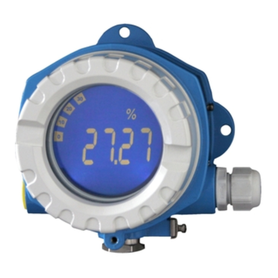
Page 20: Display And Operating Elements
Operating the field indicator RID14 Display and operating elements 5.2.1 Display a0012574 Fig. 12: LC display of the field indicator Item 1: bar graph display in increments of 10% with indicators for underranging (item 1a) and overranging (item 1b) Item 2: measured value display, digit height 26 mm (1.02"), status indication "Bad measured value status"... - Page 21 RID14 Operating the field indicator a0011300-en Fig. 13: System integration via FOUNDATION Fieldbus™ HSE = High Speed Ethernet, H1 = FOUNDATION Fieldbus-H1 The following system connection options are possible: – A linking device can be used to connect to higher ranking fieldbus protocols (e.g. to the High Speed Ethernet - HSE) (Control Net) –...
- Page 22 Operating the field indicator RID14 5.3.2 Link Active Scheduler (LAS) The FOUNDATION Fieldbus™ works according to the 'producer-consumer' relationship. This provides various advantages. Data can be directly exchanged between field devices, e.g. a sensor and an actuating valve. Each bus user ’publishes’ its data on the bus and all the bus users configured accordingly obtain this data.
- Page 23 RID14 Operating the field indicator 5.3.5 Function blocks The FOUNDATION Fieldbus™ uses predefined function blocks to describe the functions of a device and to specify uniform data access. The function blocks implemented in each fieldbus device provide information on the tasks which a device can accept in the whole of the automation strategy.
-
Page 24: Configuration Of The Indicator And Ff Functions
Operating the field indicator RID14 Configuration of the indicator and FF functions The FF communication system will only function properly if correctly configured. You can obtain special configuration and operating programs from various manufacturers for the configuration. Process control systems... -
Page 25: Hardware Settings
RID14 Operating the field indicator Hardware settings DIP switches inside the field indicator housing are used to enable and disable hardware write protection. When write protection is active, parameters cannot be modified. The current write protection status is displayed in the WRITE_LOCK parameter (Resource Block, see Section 11). -
Page 26: Commissioning
ID, device type and device serial number. It is unique and can never be assigned twice. The DEVICE_ID of the device is composed as follows: DEVICE_ID = 452B4810CF-XXXXXXXXXXX 452B48 = Endress+Hauser 10CF = RID1x XXXXXXXXXXX = device serial number (11-digit) - Page 27 (see Section 2 'Identification'). Switch the device on. The first time you establish a connection, the device reacts as follows in the configuration system: – EH_RID14-xxxxxxxxxxx (tag name PD-TAG for RID14) or EH_RID16-xxxxxxxxxxx (tag name PD-TAG for RID16) – 452B4810CF-xxxxxxxxxxx (DEVICE_ID) –...
- Page 28 Using the DEVICE_ID noted, identify the field device and assign the desired tag name (PD_TAG) to the fieldbus device in question. Factory setting: EH_RID14-xxxxxxxxxxx (for RID14, xxx... = serial number) or EH_RID16-xxxxxxxxxxx (for RID16, xxx... = serial number). Configuring the "Resource Block" (base index 400) Open the Resource Block.
-
Page 29: Maintenance
RID14 Maintenance Maintenance No special maintenance work is required on the device. Accessories Various accessories, which can be ordered separately from your supplier, are available for the device. Detailed information on the order code in question can be obtained from your service organization. -
Page 30: Trouble-Shooting
Note! In the event of a serious fault, an indicator might have to be returned to the manufacturer for repair. Follow the instructions in → Chap. 9.4 before returning the indicator to Endress+Hauser. Check local display No display visible - No connection 1. -
Page 31: Status Messages
RID14 Trouble-shooting Transducer Blocks: The device description file (Device Description, DD) has not yet been loaded to the host system or the configuration program? → Download the file to the configuration The manufacturer-specific parameters are not visible. system. For information on where to obtain the DD, → ä 23... - Page 32 Trouble-shooting RID14 Cate Status messages Display symbol Cause of error / remedy gory – CURRENT_STATUS_ NUMBER in the 'Advanced Diagnostics' Transducer Block – Local display Device status message (FF): No bargraph displayed Cause of error: Electronic board defective Error in the electronics.
-
Page 33: Spare Parts
RID14 Trouble-shooting Spare parts When ordering spare parts, please specify the serial number of the device! Type Order number Cable gland 51006845 Pipe / wall mounting kit with plastic mounting plate 51007995 Return For later reuse or to return the device to the service organization of your supplier, the device must be packed in such a way as to protect it from impact and damage. -
Page 34: Technical Data
Technical data RID14 Technical data 10.0.1 Communication • FOUNDATION Fieldbus™ H1, IEC 61158-2 • FDE (Fault Disconnection Electronic) = 0 mA • Data transmission rate: supported baud rate = 31.25 kBit/s • Signal coding = Manchester II • LAS (link active scheduler), LM (link master) function is supported: Thus, the indicator can assume the function of a link active scheduler (LAS) if the current link master (LM) is no longer available. - Page 35 RID14 Technical data Link settings Slot time Min. inter PDU delay Max. response delay Blocks Block description Block index Permanent Block execution time Block class Resource Extended Display Transducer Manufacturer-specific Advanced Diagnostic Manufacturer-specific 100 ms Standard Input Selector 1 35 ms...
- Page 36 Technical data RID14 10.0.2 Power supply Electrical connection a0011303 Abb. 15: Terminal assignment of the field display unit. Supply voltage Voltage is supplied via the fieldbus. U = 9 to 32 V DC, polarity-independent (max. voltage U = 35 V).
- Page 37 RID14 Technical data Shock and vibration resistance 10 to 2000 Hz for 5g as per IEC 60 068-2-6 Electromagnetic compatibility CE EMC conformity (EMC) The device complies with all the requirements of IEC 61326-1:2006 and NAMUR NE21:2007. This recommendation is a consistent determination as to whether the devices used in laboratories and in distributed control systems are immune to interference, thus increasing their functional safety.
- Page 38 10.0.7 Certificates and approvals CE mark The device meets the legal requirements of the EC directives. Endress+Hauser confirms that the device has been successfully tested by applying the CE mark. Ex-approval Information about currently available Ex versions (ATEX, FM, CSA, etc.) can be supplied by your E+H Sales Center on request.
- Page 39 RID14 Technical data Other standards and guideli- • IEC 60529: Degrees of protection provided by enclosures (IP code) • IEC 61010-1: Safety requirements for electrical equipment for measurement, control and laboratory use • IEC 61326 series: Electromagnetic compatibility (EMC requirements) •...
- Page 40 Technical data RID14 Endress+Hauser...
- Page 41 In addition to these blocks, a field device may have other blocks, e.g. several Input Selector function blocks if more than one process variable is available from the field device. RID1x has the following blocks: a0011646 Fig. 1: Block model RID1x Endress+Hauser...
- Page 42 – ONLINE LINKING The configured connections between the function blocks have not yet been established. – ONLINE Normal operating status, the Resource Block is in the AUTO oper- ating mode. The configured connections between the function blocks have been established. Endress+Hauser...
-
Page 43: Index
The alarm priority specifies the behavior in the event of an active write protection alarm WRITE_ALM. Note! If the option of a process alarm was not activated in the ACK_OPTION parameter, this process alarm must only be acknowledged in the BLOCK_ALM parameter. Endress+Hauser... - Page 44 Factory default: 640000 Cycle Selection AUTO - OOS Displays the block execution method used by the fieldbus host system. (CYCLE_SEL) Note! The block execution method is selected by the fieldbus host system. Endress+Hauser...
- Page 45 0. Free Space Read only Displays the free system memory (in percent) available for execution of further (FREE_SPACE) function blocks. Note! Since the function blocks of the device are preconfigured, this parameter always displays the value 0. Endress+Hauser...
- Page 46 Manufacturer ID Read only Displays the manufacturer's ID number. (MANUFAC_ID) Display: 0 x 452B48 = Endress+Hauser Max Notify Read only Displays the maximum number of event reports supported by the device that can (MAX_NOTIFY) exist unconfirmed at the same time.
- Page 47 Serial Number Read only Displays the device serial number. (SERIAL_NUMBER) Service Locking AUTO_OOS Only for service reasons. (SERVICE_LOCKING) Set Fault State AUTO - OOS This parameter can be used to manually enable the security behavior of the device. (SET_FSTATE) Endress+Hauser...
- Page 48 Displays the status of the write protected alarm. (WRITE_ALM) Note! The alarm is triggered if the write protection is disabled. Write Lock Read only Display status of write protection (WRITE_LOCK) Display: LOCKED Device data cannot be modified NOT LOCKED Device data can be modified UNINITIALIZED Endress+Hauser...
- Page 49 7 = high priority) to the fieldbus host system as a user notice. 8-15 = The write protection alarm is output with the appropriate priority (8 = low priority, 15 = high priority) to the fieldbus host system as a critical alarm. Factory default: Endress+Hauser...
- Page 50 Alert key AUTO - OOS Use this function to enter the identification number of the plant unit. (ALERT_KEY) This information can be used by the fieldbus host system for sorting alarms and events. User input: 1 to 255 Factory setting: Endress+Hauser...
- Page 51 BLOCK_ALM parameter of the Analog Input function block. Transducer Type Read only The Transducer Block type appears on the display. (TRANSDUCER_TYPE) Display: • Display Transducer Block: Custom Display Transducer • Advanced Diagnostic Block: Custom Adv. Diag. Transducer Endress+Hauser...
- Page 52 This can be read via the Transducer Block “Advanced Diagnostic” in the “CURRENT_STATUS_CATEGORY” and "CURRENT_STATUS_NUMBER" parameters. • An exact error description as well as information on rectifying faults can be found in Section 9.2. Endress+Hauser...
- Page 53 DIGITAL DISP_VALUE_4_ DISP_VALUE_1[...8]_VALUE: The current discrete value. This value is selected DIGITAL through the parameter "Source digital" or with activated "Listener mode" through DISP_VALUE_5_ the parameters "Listener device" and "Listener value select". DIGITAL DISP_VALUE_6_ DIGITAL DISP_VALUE_7_ DIGITAL DISP_VALUE_8_ DIGITAL Endress+Hauser...
- Page 54 • ISEL1.IN_2 • ISEL1.IN_3 • ISEL1.IN_4 • ISEL1.OUT • ISEL2.IN_1 • ISEL2.IN_2 • ISEL2.IN_3 • ISEL2.IN_4 • ISEL2.OUT • PID.IN • PID.OUT • PID.SP • INTG.IN_1 • INTG.IN_2 • INTG.OUT • AR.IN • AR.IN_1 • AR.IN_2 • AR.IN_3 • AR.OUT Endress+Hauser...
- Page 55 This setting is valid once a digital source is selected. Availabel parameters are: • 1 = On; 0 = Off • 0 = On; 1 = Off • 1 = Open; 0 = Close • 0 = Open; 1 = Close • display as decimal value Endress+Hauser...
- Page 56 AUTO - OOS Shows the last diagnostic number and its category. NUMBER LAST_STATUS_DESC AUTO - OOS Shows a discription to the last diagnostic message. LAST_STATUS_CHANNEL AUTO - OOS This parameter displays in which display channel the 'Last diagnostics' appeared. Endress+Hauser...
- Page 57 Indicates the maximum appeared value on display channel 1[...8] (value 1 to 8). CH2_MAX_INDICATOR This value is saved to non- volatile memory in a cycle of 10 minutes. CH3_MAX_INDICATOR CH4_MAX_INDICATOR CH5_MAX_INDICATOR CH6_MAX_INDICATOR CH7_MAX_INDICATOR CH8_MAX_INDICATOR RESET_ALL_INDICATORS AUTO - OOS Resets all min- and max- values to "0". Endress+Hauser...
- Page 58 There are no standard alarms in this function block. Custom alarms are supported. A detailed description of the Integrator function block can be found in the FOUNDATION Field- bus™ Function Blocks manual on the supplied CD-ROM (BA062S/04). Endress+Hauser...
- Page 59 RID14 Index Index Configuration Wall mounting ........9 Resource Block .
- Page 60 www.endress.com/worldwide BA282R/09/en/12.09 71092446 FM+SGML 6.0 / ProMoDo...