Endress+Hauser RID14 Operating Instructions Manual
Fieldbus indicator with profibus® pa protocol
Hide thumbs
Also See for RID14:
- Operating instructions manual (68 pages) ,
- Brief operating instructions (44 pages) ,
- Brief operating instructions (24 pages)

Related Manuals for Endress+Hauser RID14


Summary of Contents for Endress+Hauser RID14
- Page 1 Products Solutions Services BA01267K/09/EN/02.15 71288590 Operating Instructions RID14 Fieldbus indicator with PROFIBUS® PA protocol...
-
Page 3: Table Of Contents
RID14 Table of contents Table of contents 10.2 Status messages ..... . Document information ....4 10.3 Spare parts . -
Page 4: Document Information
Document information RID14 Document information Document function These Operating Instructions contain all the information that is required in various phases of the life cycle of the device: from product identification, incoming acceptance and storage, to mounting, connection, operation and commissioning through to troubleshooting, maintenance and disposal. - Page 5 RID14 Document information 1.2.3 Symbols for certain types of information Symbol Meaning Permitted Procedures, processes or actions that are permitted. Preferred Procedures, processes or actions that are preferred. Forbidden Procedures, processes or actions that are forbidden. Indicates additional information. Reference to documentation...
-
Page 6: Safety Instructions
Conversions to the device Unauthorized modifications to the device are not permitted and can lead to unforeseeable dangers. ‣ If, despite this, modifications are required, consult with Endress+Hauser. Repair To ensure continued operational safety and reliability, ‣ Carry out repairs on the device only if they are expressly permitted. -
Page 7: Product Safety
If a plastic transmitter housing is permanently exposed to certain steam and air mixtures, this can damage the housing. ‣ If you are unsure, please contact your Endress+Hauser Sales Center for clarification. ‣ If used in an approval-related area, observe the information on the nameplate. -
Page 8: Identification
The right device? Compare the order code on the nameplate of the device to that on the delivery papers. Made in Germany 2013 RID14 D-87484 Nesselwang Order code: RID14-xxxxxxx Ser. no.: xxxxxxxxxxx Ext. ord. cd.: xxxxxxxxxxxxxxxxxx IP67 NEMA4X 9 - 32 V Ta = -40 ...+80°C... - Page 9 RID14 Identification The field indicator has successfully passed the PROFIBUS PA physical layer test. As a "nonactive" bus user it does interfere with Profibus data transfer. Recognized component as per UL 3111-1. CSA General Purpose. Endress+Hauser...
-
Page 10: Installation
Installation RID14 Installation Incoming acceptance, transport, storage The permitted ambient and storage conditions must be observed. The precise specifications can be found in Section "Technical data". 4.1.1 Incoming acceptance On receipt of the goods, check the following points: • Are the packaging or contents damaged? •... -
Page 11: Installation Instructions
RID14 Installation 4.2.2 Installation location Information on conditions that must be present at the installation location to mount the device correctly can be found in Section ' T echnical data' . These include the ambient temperature, degree of protection, climate class etc. -
Page 12: Post-Installation Check
Installation RID14 A0011258 4 Mounting the field indicator on a pipe with the mounting bracket for pipe diameters 1.5 to 2.2" Mounting plate Mounting bracket 2 M6 nuts Post-installation check After installing the device, always run the following final checks:... -
Page 13: Wiring
RID14 Wiring Wiring WARNING Danger of explosion if unit is connected incorrectly in hazardous area ‣ When connecting Ex-approved devices please take special note of the instructions and connection schematics in the Ex-specific supplement to these Operating Instructions. If you have any questions, please do not hesitate to contact your E+H representative. -
Page 14: Connection To Profibus® Pa
Wiring RID14 5.1.1 Quick wiring guide ESD - electrostatic discharge Protect the terminals from electrostatic discharge. Failure to observe this may result in destruction or malfunction of parts of the electronics. A0012751 ® PROFIBUS PA A0021496 6 Terminal assignment... - Page 15 Fieldbus connector Optionally, a fieldbus connector can be installed in the field housing instead of a cable gland. Fieldbus connectors can be ordered as an accessory from Endress+Hauser (see Section "Accessories"). The PROFIBUS® PA connection technology allows measuring devices to be connected to the fieldbus via standardized mechanical connections such as T-boxes, junction box modules etc.
-
Page 16: Profibus® Pa Cable Specifications
Wiring RID14 where the cable shielding is connected to the connector housing (e.g. pre-terminated cables). M20x1.5 / NPT 1/2” SW/AF 26 A0021497 8 Connectors for connection to the PROFIBUS® PA fieldbus Pin assignment / color codes Fieldbus connector 7/8" connector... - Page 17 RID14 Wiring The electrical data of the fieldbus cable have not been specified but determine important characteristics of the design of the fieldbus, such as distances bridged, number of users, electromagnetic compatibility, etc. Type A Type B Cable structure Twisted pair of cores, shielded Individual or multiple pairs of...
- Page 18 Wiring RID14 5.3.5 Shielding and grounding NOTICE Equalizing current can damage the bus cable or bus shield ‣ If the shielding of the cable is grounded at more than one point in systems without potential matching, mains frequency equalizing currents can occur that damage the bus cable or the bus shield or have a serious effect on signal transmission.
-
Page 19: Degree Of Protection
RID14 Wiring a switch. If this is not the case, a separate bus terminator must be installed. Please also note the following: • In the case of a branched bus segment, the measuring device furthest from the segment coupler represents the end of the bus. - Page 20 Wiring RID14 Electrical connection Notes Has the max. length of the spurs, as defined in the fieldbus specifications, been observed? Is the fieldbus cable completely shielded (90%) and correctly grounded? Endress+Hauser...
-
Page 21: Operating The Field Indicator
RID14 Operating the field indicator Operating the field indicator Quick operation guide Operators have two options for configuring and commissioning the device: 1. Configuration programs Device-specific parameters are configured via the E+H Service interface (CDI). A special device driver (DTM) for an FDT operating program (e.g. DeviceCare, FieldCare) is available for this purpose →... -
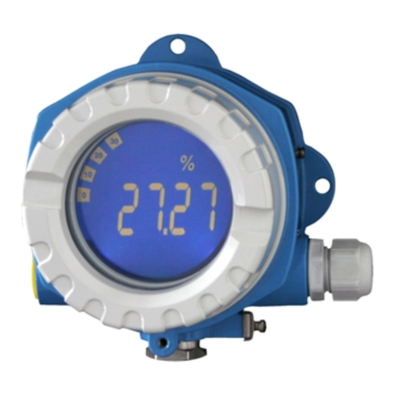
Page 22: Display And Operating Elements
Operating the field indicator RID14 Display and operating elements 6.2.1 Display A0012574 11 LC display of the field indicator Bar graph display in increments of 10% with indicators for underranging (item 1a) and overranging (item 1b) Measured value display, status indication "Bad measured value status"... - Page 23 RID14 Operating the field indicator available at: www.endress.com/download → Advanced → "Documentation code" BA00034S. 6.3.1 System architecture The following figure shows an example of a PROFIBUS® network with the associated components. Visualization and monitoring e. g. P View, FieldCare and diagnostic software...
-
Page 24: Configuration Of The Field Indicator
Operating the field indicator RID14 field devices are configured via a Class 2 PROFIBUS DP master, such as FieldCare. The field devices on the PROFIBUS PA segment are the slaves. Segment coupler From the point of view of the PROFIBUS DP master, segment couplers are transparent and are therefore not configured in the PLC, i.e. -
Page 25: Hardware Settings
2. In the settings for the Comm DTM, set the baud rate to 2400 baud and set the COM port used. 3. Add the device DTM "RID14/16 / Vx.xx.xx" to the project via the "Add device.." function. 4. Continue the device configuration as described in these Operating Instructions for the device. - Page 26 Operating the field indicator RID14 To set the DIP switches, proceed as follows: 1. Remove the housing cover and remove the display → 5, 13 2. Configure the DIP switches. Switch to ON = function enabled, switch to OFF = function disabled.
- Page 27 RID14 Operating the field indicator 2. Set the DIP switch "Adress/Offset" to "ON", the bus address of the measuring device whose values are to be displayed can be set using DIP switches 1 to 64. Valid address range: 0 to 125 3.
-
Page 28: Commissioning
Commissioning RID14 Commissioning Post-installation check Make sure that all post-connection checks have been carried out before putting your devices into operation: • Checklist for "post-installation check" → 12 • Checklist for "post-connection check" → 19 The functional data of the PROFIBUS® PA interface according to IEC 61158-2 (MBP) must be observed. -
Page 29: Maintenance
RID14 Maintenance Maintenance No special maintenance work is required on the device. Endress+Hauser... -
Page 30: Accessories
Various accessories, which can be ordered with the device or subsequently from Endress +Hauser, are available for the device. Detailed information on the order code in question is available from your local Endress+Hauser sales center or on the product page of the Endress+Hauser website: www.endress.com. -
Page 31: Troubleshooting
RID14 Troubleshooting Troubleshooting 10.1 Troubleshooting instructions In the event of a serious fault, an indicator might have to be returned to the manufacturer for repair. Follow the instructions in → 35 before returning the indicator. Always start troubleshooting with the checklists below if faults occur after start up or during operation. -
Page 32: Status Messages
Troubleshooting RID14 10.2 Status messages The device displays warnings or alarms as status messages. If errors occur during commissioning, these errors are displayed immediately. A distinction is made here between the following 4 status categories: Status category Description Error category... - Page 33 3x thread NPT1/2, without terminal block 3x M20x1.5, without terminal block 3x thread G1/2, without terminal block Version: Standard RIA141G- ← Order code cpl. housing RID14 Item No. Type Order number Housing cover cpl. display aluminum Ex d + RIA141X-HK seal Housing cover cpl.
-
Page 34: Software History And Overview Of Compatibility
Troubleshooting RID14 Item No. Type Order number Plug (dummy) NPT1/2" ALU 51004490 Plug (dummy) G1/2" EEx-d/XP 51004916 Plug (dummy) NPT1/2"V4A 51006888 Mounting bracket, pipe 1.5-3", stainless steel 51007995 316L 10.4 Software history and overview of compatibility Release The release number on the nameplate and in the Operating Instructions indicates the device release: XX.YY.ZZ (example 01.02.01). -
Page 35: Return
The measuring device must be returned if it is need of repair or a factory calibration, or if the wrong measuring device has been delivered or ordered. Legal specifications require Endress+Hauser, as an ISO-certified company, to follow certain procedures when handling products that are in contact with the medium. -
Page 36: Disposal
Disposal RID14 Disposal The device contains electronic components and must therefore be disposed of as electronic waste. Comply with local disposal regulations. Endress+Hauser... -
Page 37: Technical Data
Indicator for PROFIBUS PA, can be used in conjunction with PROFILE 2 and PROFILE 3 (3.0, 3.01 and 3.02) devices Device master files (GSD) How to acquire device master files (GSD) and device drivers: FieldCare/DTM: www.endress.com/download → Product Code RID14 or RID16 → Media Type "Software" → "Device Drivers" Write protection Write protection enabled by hardware setting (DIP switch) 13.2... -
Page 38: Installation
Technical Data RID14 13.2.2 Supply voltage Voltage is supplied via the fieldbus. U = 9 to 32 V , polarity-independent (max. voltage U = 35 V). 13.2.3 Mains voltage filter 50/60 Hz 13.2.4 Current consumption ≤ 11 mA 13.2.5 Cable entry The following cable entries are available: •... - Page 39 RID14 Technical Data 13.4.5 Humidity • Condensation permitted as per IEC 60 068-2-33 • Max. rel. humidity: 95% as per IEC 60068-2-30 13.4.6 Degree of protection IP67. NEMA 4X. 13.4.7 Shock and vibration resistance 10 to 2 000 Hz for 5g as per IEC 60 068-2-6 13.4.8...
-
Page 40: Mechanical Construction
Technical Data RID14 13.5 Mechanical construction 13.5.1 Design, dimensions 132 (5.2) 112 (4.4) 106 (4.2) 121 (4.8) 166 (6.5) A0011152 18 Dimensions of the field indicator; dimensions in mm (in) • Aluminum housing for general applications or optional stainless steel housing •... -
Page 41: Operability
RID14 Technical Data 13.6 Operability 13.6.1 Local operation Display elements A0011307 19 LC display of the field indicator (backlit, pluggable in 90° stages) bar graph display in increments of 10% with indicators for underranging (item 1a) and overranging (item 1b) measured value display, digit height 20.5 mm (0.8 in), status indication "Bad measured value status"... -
Page 42: Documentation
• System Components and Data Managers - Solutions for the loop: FA00016K/09 • Competence Brochure PROFIBUS - Process automation with digital fieldbus technology: CP00005S/04 • Technical Information RID14, 8-channel field indicator with FOUNDATION Fieldbus™ or PROFIBUS® PA protocol: TI00145R/09 Technical Information RID16, 8-channel field indicator with FOUNDATION Fieldbus™ or PROFIBUS®... -
Page 43: Appendix
RID14 Appendix Appendix 14.1 DTM operating parameters 14.1.1 Operation menu Display duration Navigation Operation → Alternating time Description Use this function to set the length of time the measured values are displayed if the values alternate on the display. The display only alternates automatically between values if more than one measured value is defined. - Page 44 Appendix RID14 Navigation Operation → "Display value X" submenu → Description Description Possibility to enter a user-defined text with a maximum of 16 characters. This text is shown below the value on the display. If the text is longer than 5 characters, it is displayed as marquee text.
- Page 45 RID14 Appendix Description Use this function to select the number of decimal places for the display value. This setting does not affect the accuracy of the device when measuring or calculating. Only visible if data type = analog. Options • Automatic •...
- Page 46 Appendix RID14 Description Displays the device locking status. The DIP switch for hardware locking is provided on the display module. Write access to the parameters is locked if write protection is enabled. Only read access • Not locked • Hardware locked...
- Page 47 RID14 Appendix Description Displays the order code of the device. It can also be found on the nameplate. The code is generated by reversibly transforming the extended order code which indicates the attribute of all the device features in the product structure.
- Page 48 Appendix RID14 Factory setting Operator Additional information • Visible offline: Yes • Writable offline: No "System" submenu Navigation Expert → System Description This submenu contains system settings. Locking status Navigation Expert→ System → Locking status Description Displays the device locking status.
- Page 49 RID14 Appendix Data direction Navigation Expert → Display → Display value x → Data direction Description For selecting the direction of the data that are to be displayed. It is possible to display data that are sent from the device (slave) to the master or from the master to the field device.
- Page 50 Appendix RID14 Description Select how the digital values are represented. Only visible if data type = digital. Options • 1 = On; 0 = Off • 0 = On; 1 = Off • 1 = Open; 0 = Close • 0 = Open; 1 = Close •...
- Page 51 RID14 Appendix Navigation Expert → Diagnostics → Device information → Manufacturer name Description Displays the manufacturer name. Only read access. Factory setting Endress+Hauser Additional information • Visible offline: Yes • Writable offline: No Endress+Hauser...
-
Page 52: Index
Index RID14 Index Addressing ....... . 24 Nameplate ....... . . 8 Number of field devices . - Page 53 RID14 Index Submenu Device information ..... 46, 50 Device reset ......47 Diagnostics .
- Page 56 www.addresses.endress.com...