Table of Contents
Advertisement
Quick Links
KA01149O/09/EN/02.13
71229793
Brief Operating Instructions
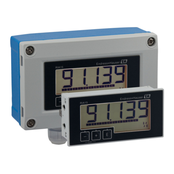
Loop-powered display unit
with HART
®
communication
ORIA15
These instructions are Brief Operating Instructions; they do not
replace the Operating Instructions included in the scope of
supply.
For detailed information, refer to the Operating Instructions
and other documentation on the CD-ROM provided.
Advertisement
Table of Contents

Related Manuals for Endress+Hauser ORIA15


Summary of Contents for Endress+Hauser ORIA15
- Page 1 Brief Operating Instructions Loop-powered display unit with HART ® communication ORIA15 These instructions are Brief Operating Instructions; they do not replace the Operating Instructions included in the scope of supply. For detailed information, refer to the Operating Instructions and other documentation on the CD-ROM provided.
-
Page 2: Table Of Contents
Table of contents Loop-powered display unit Table of contents Document information ........... . . 2 Document conventions . - Page 3 Loop-powered display unit Document information Symbol Meaning CAUTION! CAUTION This symbol alerts you to a dangerous situation. Failure to avoid this situation can result in minor or medium injury. A0011191-EN NOTICE! NOTICE This symbol contains information on procedures and other facts which do not result in personal injury.
- Page 4 Document information Loop-powered display unit Symbol Meaning Indicates additional information. A0011193 Reference to documentation Refers to the corresponding device documentation. A0011194 Reference to page Refers to the corresponding page number. A0011195 Reference to graphic Refers to the corresponding graphic number and page number. A0011196 Series of steps …...
-
Page 5: Registered Trademarks
Loop-powered display unit Safety instructions Symbol Meaning Open-ended wrench A0011222 Torx screwdriver A0013442 Registered trademarks ® HART Registered trademark of the HART ® Communication Foundation Safety instructions Requirements for the personnel The personnel must fulfill the following requirements for its tasks: ‣... -
Page 6: Workplace Safety
Identification Loop-powered display unit Workplace safety For work on and with the device: ‣ Wear the required personal protective equipment according to federal/national regulations. Operational safety Risk of injury! ‣ Operate the device in proper technical condition and fail-safe condition only. ‣... -
Page 7: Scope Of Delivery
Loop-powered display unit Identification Ta=-40...+60°C (-40...+140°F) Loop Powered Loop powered 4...20mA Display Front IP65 NEMA Type 4x Encl. FW: XX.XX.XX ident: xxxxxxxxxxxxxxxx S/N: XXXXXXXXXXXX A0019058 Device designation Serial number of the device Housing degree of protection Order code of the device Manufacturer' s address Input signal Approvals (optional) -
Page 8: Hart ® Protocol Certification
Installation Loop-powered display unit The device described in these Operating Instructions therefore complies with the statutory requirements of the EU Directives. The manufacturer confirms that the device has been successfully tested by applying the CE mark. HART ® protocol certification The process display unit is registered by the HART ®... -
Page 9: Installation Instructions
Loop-powered display unit Installation See "Technical data" section in the relevant Operating Instructions. Installation instructions For the dimensions of the device, see the "Technical data" section in the relevant Operating Instructions. 4.3.1 Panel housing A0017762 1 Installation instructions for the panel housing Installation in a panel with a panel cutout 92x45 mm (3.62x1.77 in), max. - Page 10 Installation Loop-powered display unit TX20 A0017789 2 Mounting the process display unit on a pipe Mounting plate for pipe/wall mounting Weather protection cover (optional) Release the 4 housing screws Open the housing Secure the mounting plate to the rear of the device with 4 screws supplied. The optional weather protection cover can be secured between the device and the mounting plate.
- Page 11 Loop-powered display unit Installation Wall mounting With optionally available mounting kit. A0017803 3 Mounting the process display unit on a wall Use the mounting plate as a stencil for 2 6 mm (0.24 in) bore holes, 82 mm (3.23 in) apart, and secure the plate on the wall with 2 screws (not supplied).
- Page 12 Installation Loop-powered display unit Secure the display unit on the wall with 4 screws. Close the cover and tighten the housing screws. 4.3.3 ® Mounting the optional HART communication resistance module Panel housing The HART ® communication resistance module is available as an accessory, see section Accessories in the relevant Operating instructions.
-
Page 13: Post-Installation Check
Loop-powered display unit Wiring A0020844 5 Mounting the optional HART ® communication resistance module Unplug the pluggable terminal block. Plug terminal block into the suitable plug-in position on the HART ® communication resistance module. Plug the HART ® communication resistance module into the plug-in position in the housing. -
Page 14: Quick Wiring Guide
Wiring Loop-powered display unit Only certified devices (optionally available) may be connected in the hazardous area ‣ Observe corresponding notes and wiring diagrams in the Ex-specific supplement to these Operating Instructions. Your supplier is available for assistance if required. NOTICE SELV / Class 2 device ‣... -
Page 15: Connection In 4 To 20 Ma Mode
Loop-powered display unit Wiring Terminal Description Auxiliary terminals (electrically connected internally) Functional grounding: • Panel-mounted device: Terminal on the rear of the housing • Field device: Terminal in the housing Connection in 4 to 20 mA mode The following diagrams show how the process display unit is connected in 4 to 20 mA mode. -
Page 16: Connection In Hart Mode
Wiring Loop-powered display unit Connection without backlighting Connection with backlighting Connection with PLC and transmitter A0019720 A0019721 1 PLC 1 PLC Connection without transmitter power supply directly in the 4 to 20 mA circuit A0017708 A0017709 2 4 to 20 mA power source 2 4 to 20 mA power source Connection in HART mode The following diagrams show how the process display unit is connected in HART mode. - Page 17 Loop-powered display unit Wiring ® The HART communication resistance of 230 Ω in the signal line is always necessary in the case of a low-impedance power supply. It must be installed between the power supply and the display unit. Circuit diagram / Description 2-wire sensor with process display unit and loop power supply,...
- Page 18 Wiring Loop-powered display unit Circuit diagram / Description 4-wire sensor with process display unit and loop power supply, with backlighting A0019571 HART ® resistance Current meter (optional) Sensor Power supply 4-wire device Current output with process display unit and actuator (e.g. actuator valve), without backlighting A0019573...
- Page 19 Loop-powered display unit Wiring Circuit diagram / Description Multi-drop 2-wire sensors with process display unit and loop power supply A0019575 Sensors Power supply ® HART resistance Multi-drop 2-wire sensors with process display unit and loop power supply, with backlighting A0019722 Sensors Power supply HART...
- Page 20 Wiring Loop-powered display unit Wiring Circuit diagram / Description 2-wire sensor with process display unit and loop power supply, without backlighting A0020839 HART ® communication resistance module Sensor Power supply 2-wire sensor with process display unit and loop power supply, with backlighting A0020840 ®...
- Page 21 Loop-powered display unit Wiring Circuit diagram / Description 4-wire sensor with process display unit and loop power supply, without backlighting A0020837 HART ® communication resistance module Power supply of 4-wire device Sensor 4-wire sensor with process display unit and loop power supply, with backlighting A0020838 HART...
-
Page 22: Inserting The Cable, Field Housing
Wiring Loop-powered display unit Inserting the cable, field housing TX20 A0017830 7 Inserting the cable, field housing Inserting the cable, field housing, connection without transmitter power supply (example) Release the housing screws Open the housing Open the cable gland (M16) and insert the cable. Connect the cable incl. -
Page 23: Connecting To Functional Grounding
Loop-powered display unit Wiring The best results with regard to EMC are achieved in most cases with one-sided shielding on the feed side (without capacitance termination at the field device). Operation in the event of disturbance variables as per NAMUR NE21 is thus guaranteed. -
Page 24: Degree Of Protection
Wiring Loop-powered display unit TX20 A0018895 9 Functional grounding terminal in field housing TX20 A0018908 10 Ground terminal on field housing Degree of protection 5.7.1 Field housing The devices meet all the requirements of IP66. It is absolutely essential to comply with the following points to ensure this protection is guaranteed after mounting or servicing the device: •... -
Page 25: Post-Connection Check
Loop-powered display unit Operation 5.7.2 Panel housing The front of the device meets the requirements of IP65. It is absolutely essential to comply with the following points to ensure this protection is guaranteed after mounting or servicing the device: • The seal between the front of the housing and the panel must be clean and undamaged. -
Page 26: Operating Functions
Operation Loop-powered display unit The device is operated using three operating keys on the front of the housing. The device setup can be disabled with a 4-digit user code. If the setup is disabled, a padlock symbol appears on the display when an operating parameter is selected. Enter key;...