Endress+Hauser RID14 Brief Operating Instructions
Fieldbus indicator with foundation fieldbus - protocol
Hide thumbs
Also See for RID14:
- Operating instructions manual (68 pages) ,
- Brief operating instructions (24 pages) ,
- Operating instructions manual (60 pages)
Table of Contents
Advertisement
Available languages
Available languages
Quick Links
KA00281R/09/A2/14.16
71335915
Products
Brief Operating Instructions
RID14
Fieldbus indicator
with FOUNDATION Fieldbus™ - protocol
These Instructions are Brief Operating Instructions; they are
not a substitute for the Operating Instructions pertaining to
the device.
For detailed information, refer to the Operating Instructions
and other documentation.
Available for all device versions via:
• Internet: www.endress.com/deviceviewer
• Smart phone/Tablet: Endress+Hauser Operations App
Solutions
50
40
30
20
10
0
Services
Advertisement
Chapters
Table of Contents

Related Manuals for Endress+Hauser RID14


Summary of Contents for Endress+Hauser RID14
- Page 1 These Instructions are Brief Operating Instructions; they are not a substitute for the Operating Instructions pertaining to the device. For detailed information, refer to the Operating Instructions and other documentation. Available for all device versions via: • Internet: www.endress.com/deviceviewer • Smart phone/Tablet: Endress+Hauser Operations App...
- Page 2 RID14 Order code: XXXXX-XXXXXX Ser. no.: XXXXXXXXXXXX Ext. ord. cd.: XXX.XXXX.XX Serial number www.endress.com/deviceviewer Endress+Hauser Operations App A0023555 Endress+Hauser...
- Page 3 RID14 RID14 Fieldbus indicator with FOUNDATION Fieldbus™ - protocol Kurzanleitung ............... . . 4 Brief Operating Instructions .
-
Page 4: Table Of Contents
Inhaltsverzeichnis RID14 Inhaltsverzeichnis Hinweise zum Dokument ............5 Darstellungskonventionen . -
Page 5: Hinweise Zum Dokument
RID14 Hinweise zum Dokument Hinweise zum Dokument Darstellungskonventionen 1.1.1 Warnhinweissymbole Symbol Bedeutung GEFAHR! GEFAHR Dieser Hinweis macht auf eine gefährliche Situation aufmerksam, die, wenn sie nicht vermieden wird, zu Tod oder schwerer Körperverletzung führen wird. WARNUNG! Dieser Hinweis macht auf eine gefährliche Situation aufmerksam, die, wenn sie nicht WARNUNG vermieden wird, zu Tod oder schwerer Körperverletzung führen kann. - Page 6 Hinweise zum Dokument RID14 1.1.3 Symbole für Informationstypen Symbol Bedeutung Symbol Bedeutung Erlaubt Zu bevorzugen Abläufe, Prozesse oder Handlungen, Abläufe, Prozesse oder Handlungen, die erlaubt sind. die zu bevorzugen sind. Verboten Tipp Abläufe, Prozesse oder Handlungen, Kennzeichnet zusätzliche die verboten sind.
-
Page 7: Sicherheitshinweise
RID14 Sicherheitshinweise Symbol Bedeutung Gabelschlüssel A0011222 Torx Schraubendreher A0013442 Sicherheitshinweise Anforderungen an das Personal Das Personal muss für seine Tätigkeiten folgende Bedingungen erfüllen: ‣ Ausgebildetes Fachpersonal: Verfügt über Qualifikation, die dieser Funktion und Tätigkeit entspricht. ‣ Vom Anlagenbetreiber autorisiert. ‣... -
Page 8: Identifizierung
Identifizierung RID14 Es erfüllt die allgemeinen Sicherheitsanforderungen und gesetzlichen Anforderungen. Zudem ist es konform zu den EG-Richtlinien, die in der gerätespezifischen EG-Konformitätserklärung aufgelistet sind. Mit der Anbringung des CE-Zeichens bestätigt Endress+Hauser diesen Sachverhalt. Identifizierung Gerätebezeichnung 3.1.1 Typenschild Das richtige Gerät? Vergleichen Sie das Typenschild am Gerät mit folgender Abbildung:... -
Page 9: Lieferumfang
RID14 Identifizierung Lieferumfang Der Lieferumfang des Feldanzeigers besteht aus: • Feldanzeiger • Kurzanleitung in Papierform • ATEX - Sicherheitshinweise für den Einsatz eines im explosionsgefährdeten Bereich zulässigen Gerätes, optional • Optionales Zubehör (z.B. Rohrmontagehalter), siehe Kapitel ’Zubehör’ in der Betriebsanleitung Zertifikate und Zulassungen 3.3.1... -
Page 10: Montage
Montage RID14 Montage Warenannahme, Transport, Lagerung Die zulässigen Umgebungs- und Lagerbedingungen sind einzuhalten. Genaue Spezifikationen hierzu finden Sie im Kapitel "Technische Daten" in der Betriebsanleitung. 4.1.1 Warenannahme Kontrollieren Sie bei der Warenannahme folgende Punkte: • Sind Verpackung oder Inhalt beschädigt? •... -
Page 11: Montageanleitung
RID14 Montage 4.2.1 Abmessungen 132 (5.2) 112 (4.4) 106 (4.2) 121 (4.8) 166 (6.5) A0011152 2 Abmessungen des Feldanzeigers; Angaben in mm (in) 4.2.2 Montageort Informationen über Bedingungen, die am Montageort vorliegen müssen, um das Gerät bestimmungsgemäß zu montieren, wie Umgebungstemperatur, Schutzart, Klimaklasse etc., finden Sie in Kapitel "Technische Daten"... -
Page 12: Montagekontrolle
Montage RID14 Das Display kann in 90° Schritten gedreht werden. Zuerst die Deckelkralle (1) und den Gehäusedeckel (2) entfernen. Dann das Display (3) von der Elektronikeinheit (4) abziehen. Zur Parametrierung muss das Flachbandkabel zwischen Display und Elektronikeinheit eingesteckt sein. Display in die gewünschte Position drehen und dann auf die Elektronikeinheit stecken. -
Page 13: Verdrahtung
RID14 Verdrahtung Gerätezustand und -spezifikationen Hinweise Ist das Gerät sicher an der Wand bzw. auf der Montageplatte befestigt? Ist der Gehäusedeckel fest geschlossen? Entspricht das Gerät den Messstellenspezifikationen, z.B. Umgebungstemperatur usw.? Siehe Kapitel ' T echnische Daten' Verdrahtung WARNUNG Explosionsgefahr durch fehlerhaften Anschluss im Ex-Bereich ‣... - Page 14 Verdrahtung RID14 A0012568 5 Gehäuse des Feldanzeigers öffnen Kabelverschraubung öffnen bzw. Kabelverschraubung entfernen für Verwendung eines Feldbus-Gerätesteckers (optionales Zubehör). Deckelkralle entfernen. Gehäusedeckel entfernen. Display entfernen. Schrauben von der Elektronikeinheit entfernen. Elektronikeinheit abziehen. Kabel durch die Kabeleinführung ziehen bzw. Feldbus-Gerätestecker in das Gehäuse schrauben.
-
Page 15: Anschluss An Foundation Fieldbus
RID14 Verdrahtung FOUNDATION Fieldbus A0012569 6 Klemmenbelegung Klemme Klemmenbelegung FOUNDATION Fieldbus™ Anschluss (+) FOUNDATION Fieldbus™ Anschluss (-) Anschluss an FOUNDATION Fieldbus™ Der Anschluss von Geräten an den FOUNDATION Fieldbus™ kann auf zwei Arten erfolgen: • Über herkömmliche Kabelverschraubung → 15 •... - Page 16 5.2.2 Feldbus-Gerätestecker Optional kann in das Feldgehäuse, anstelle einer Kabelverschraubung, ein Feldbus Gerätestecker eingeschraubt werden. Feldbus-Gerätestecker können bei Endress+Hauser als Zubehörteil bestellt werden (siehe Kap. ’Zubehör’ in der Betriebsanleitung). Die Anschlusstechnik beim FOUNDATION Fieldbus™ ermöglicht es, Messgeräte über einheitliche mechanische Anschlüsse wie T-Abzweiger, Verteilerbausteine usw. an den Feldbus anzuschließen.
-
Page 17: Schutzart
RID14 Verdrahtung 26.5 mm (1.040") 250 mm (9.84”) 150 mm (5.91”) M20x1.5 / NPT 1/2” 7/8-16 UNC A0012573 8 Gerätestecker für den Anschluss an den FOUNDATION Fieldbus™ Pin-Belegung / Farbcodes Feldbus-Gerätestecker Blaue Leitung: FF- (Klemme 2) Feldanzeiger Braune Leitung: FF+ (Klemme 1) Graue Leitung: Schirmung Grün/gelbe Leitung: Erde... -
Page 18: Anschlusskontrolle
Bedienung des Feldanzeigers RID14 Anschlusskontrolle Führen Sie nach der elektrischen Installation des Gerätes folgende Kontrollen durch: Gerätezustand und -spezifikationen Hinweise Sind Messgerät oder Kabel beschädigt (Sichtkontrolle)? Elektrischer Anschluss Hinweise Stimmt die Versorgungsspannung mit den Angaben auf dem Typenschild überein? 9…32 V Erfüllen die verwendeten Kabel die erforderliche Spezifikationen? - Page 19 RID14 Bedienung des Feldanzeigers 2. Miniaturschalter (DIP-Schalter) für diverse Hardware-Einstellungen Über Miniaturschalter (DIP-Schalter) auf dem Elektronikmodul können folgende Hardware- Einstellungen für die Feldbus-Schnittstelle vorgenommen werden → 21: Ein-/Ausschalten des Hardwareschreibschutzes Not used WRITE LOCK A0011638 9 Hardware Konfiuration des Feldanzeigers 6.1.1...
-
Page 20: Anzeige- Und Bedienelemente
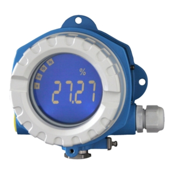
Bedienung des Feldanzeigers RID14 Anzeige- und Bedienelemente 6.2.1 Anzeige A0012574 10 LC Display des Feldanzeigers Bargraph-Anzeige in 10% Schritten mit Unter- (Pos. 1a) und Überbereichanzeige (Pos. 1b) Messwertanzeige, Statusanzeige "Schlechter Messwertstatus" 14-Segmentanzeige für Einheiten und Messages Symbol "Kommunikation" Symbol "Parameter kann nicht verändert werden"... -
Page 21: Konfiguration Des Feldanzeigers
RID14 Bedienung des Feldanzeigers Konfiguration des Feldanzeigers HINWEIS Verlust des Explosionsschutzes bei geöffnetem Gehäuse ‣ Parametrierung muss außerhalb des explosionsgefährdeten Bereichs erfolgen. Das FF-Kommunikationssystem funktioniert nur dann einwandfrei, wenn es fachkundig und korrekt konfiguriert wird. Für die Konfiguration stehen dem Benutzer spezielle, von unterschiedlichen Herstellern angebotene Konfigurations- und Bedienprogramme zur Verfügung. -
Page 22: Gerätekonfiguration
Bedienung des Feldanzeigers RID14 Der aktuelle Status des Schreibschutzes wird im WRITE_LOCK Parameter angezeigt (Resource Block, siehe Anhang in der Betriebsanleitung). ESD - Electrostatic Discharge Schützen Sie die Klemmen vor elektrostatischer Entladung. Ein Nichtbeachten kann zur Zerstörung oder Fehlfunktion von Teilen der Elektronik führen. - Page 23 RID14 Table of contents Table of contents Document information ............24 Document conventions .
-
Page 24: Document Information
Document information RID14 Document information Document conventions 1.1.1 Safety symbols Symbol Meaning DANGER! This symbol alerts you to a dangerous situation. Failure to avoid this situation will result in DANGER serious or fatal injury. WARNING! WARNING This symbol alerts you to a dangerous situation. Failure to avoid this situation can result in serious or fatal injury. - Page 25 RID14 Document information 1.1.3 Symbols for certain types of information Symbol Meaning Symbol Meaning Permitted Preferred Procedures, processes or actions that Procedures, processes or actions that are permitted. are preferred. Forbidden Procedures, processes or actions that Indicates additional information. are forbidden.
-
Page 26: Safety Instructions
Safety instructions RID14 Symbol Meaning Open-ended wrench A0011222 Torx screwdriver A0013442 Safety instructions Requirements for personnel The personnel must fulfill the following requirements for its tasks: ‣ Trained, qualified specialists must have a relevant qualification for this specific function and task. -
Page 27: Product Safety
It meets general safety standards and legal requirements. It also complies with the EC directives listed in the device-specific EC Declaration of Conformity. Endress+Hauser confirms this by affixing the CE mark to the device. Identification Device designation 3.1.1... -
Page 28: Scope Of Delivery
The measuring system meets the legal requirements of the applicable EC guidelines. These are listed in the corresponding EC Declaration of Conformity together with the standards applied. Endress+Hauser confirms successful testing of the device by affixing to it the CE mark. 3.3.2 UL approval UL recognized component (see www.ul.com/database, search for Keyword "E225237") -
Page 29: Installation
RID14 Installation Installation Incoming acceptance, transport, storage The permitted ambient and storage conditions must be observed. The precise specifications can be found in Section "Technical data" in the Operating Instructions. 4.1.1 Incoming acceptance On receipt of the goods, check the following points: •... -
Page 30: Installation Instructions
Installation RID14 4.2.1 Dimensions 132 (5.2) 112 (4.4) 106 (4.2) 121 (4.8) 166 (6.5) A0011152 2 Dimension of the filed indicator in mm (in) 4.2.2 Installation location Information on conditions that must be present at the installation location to mount the device correctly can be found in Section ' T echnical data' in the Operating Instructions. -
Page 31: Post-Installation Check
RID14 Installation The display unit can be turned in 90 ° stages. First remove the cover clamp (1) and the housing cover (2). Then disconnect the display (3) from the electronics unit (4). Turn the display to the desired position and then fit it onto the electronics unit. -
Page 32: Wiring
Wiring RID14 Device condition and specifications Notes Is the front cover fixed tightly? Does the device correspond to the measuring point specifications, e.g. ambient See ' T echnical data' section temperature range etc.? Wiring WARNING Danger of explosion if unit is connected incorrectly in hazardous area ‣... -
Page 33: Connection To The Foundation Fieldbus
RID14 Wiring Open the cable gland, or remove the cable gland to use a fieldbus connector (optional accessory). Remove the cover clamp. Remove the housing cover. Remove the display. Remove the screws from the electronics unit. Remove the electronics unit. - Page 34 Wiring RID14 NOTICE The device and fieldbus cable can be damaged by electrical voltage ‣ Switch off power supply before installing or connecting the device. ‣ It is recommended to ground the unit via one of the grounding screws. ‣...
- Page 35 Fieldbus connector Optionally, a fieldbus connector can be installed in field housing instead of a cable gland. Fieldbus connectors can be ordered from Endress+Hauser as an accessory (see Section ' A ccessories' in the Operating Instructions). The connection technology of FOUNDATION Fieldbus™ allows measuring devices to be connected to the fieldbus via uniform mechanical connections such as T-boxes, junction boxes, etc.
-
Page 36: Degree Of Protection
Wiring RID14 Degree of protection The devices fulfill the requirements for IP 67 degree of protection. Compliance with the following points is mandatory to ensure IP 67 protection is guaranteed after installation or after service work: • The housing seal must be clean and undamaged when it is inserted into the groove. The seal should be cleaned, dried or replaced. -
Page 37: Operating The Field Indicator
RID14 Operating the field indicator Operating the field indicator Quick operation guide Operators have two options for configuring and commissioning the device: 1. Configuration programs The configuration of FF functions and device-specific parameters is done via the fieldbus interface. You can obtain special configuration and operating programs from various manufacturers for these purposes →... -
Page 38: Display And Operating Elements
Operating the field indicator RID14 Display and operating elements 6.2.1 Display A0012574 10 LC display of the field indicator Bar graph display in increments of 10% with indicators for underranging (item 1a) and overranging (item 1b) Measured value display, status indication "Bad measured value status"... -
Page 39: Configuration Of The Field Indicator
RID14 Operating the field indicator Configuration of the field indicator NOTICE The device is not explosion-protected when the housing is open ‣ The device must be configured outside the hazardous area. The FF communication system will only function properly if correctly configured. You can obtain special configuration and operating programs from various manufacturers for the configuration. -
Page 40: Device Configuration
Operating the field indicator RID14 To set the DIP switches, proceed as follows: Remove the housing cover and remove the display → 5, 32 Configure the DIP switches. Switch to ON = function enabled, switch to OFF = function disabled. - Page 44 www.addresses.endress.com...