
Related Manuals for Viessmann Vitoligno 300-H


Summary of Contents for Viessmann Vitoligno 300-H
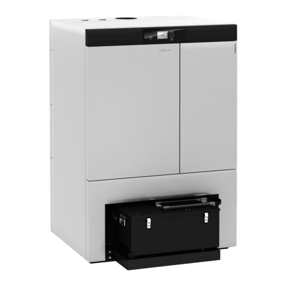
- Page 1 Viesmann Installation and service instructions for contractors Vitoligno 300-H Type VH3, 50 to 60 kW Boiler for woodchips and pellets VITOLIGNO 300-H Please keep safe. 5679249 GB 10/2019...
- Page 2 Safety instructions Safety instructions Please follow these safety instruc- tions closely to prevent accidents and material losses. Safety instructions explained Danger Note This symbol warns against the risk Details identified by the word "Note" of injury. contain additional information. Please note This symbol warns against the risk of material losses and environmen- tal pollution.
- Page 3 Repairing components that fulfil a safety function can compromise the safe operation of the system. Replace faulty components only with genuine Viessmann spare parts. Safety instructions for operating the system If you smell flue gas What to do if water escapes from the...
- Page 4 Safety instructions Safety instructions (cont.) Condensate Extractors Danger Operating appliances that extract air to Contact with condensate can be the outside (extractor hoods, extractors, harmful to health. air conditioning units, etc.) can create Never let condensate touch your negative pressure. If the boiler is oper- skin or eyes and do not swallow it.
- Page 5 Index Index 1. Information Disposal of packaging ................Symbols ....................Intended use ..................Spare parts lists ..................Safety instructions regarding maintenance and cleaning ...... 2. Preparing for installation Boiler room requirements ..............10 Boiler room floor requirements ............10 ■ Handling ....................
- Page 6 Index Index Overview of coding level 2 ..............105 ■ General ....................106 ■ Boiler ....................106 ■ Charging ..................... 108 ■ Heating ....................109 ■ DHW (DHW heater) ................111 ■ Controllers ..................111 ■ 6. Diagnosis and service Service functions ................... 112 checks Calling up the service menu ...............
- Page 7 Index Index (cont.) Heating water buffer cylinder .............. 133 ■ Solar circuit control ................135 ■ Heating circuit control ................. 135 ■ Cylinder temperature control .............. 138 ■ Vacuum supply system ................139 Supply process ................... 140 ■ Combustion flow chart ................141 10.
- Page 8 Information Disposal of packaging Please dispose of packaging waste in line with statu- tory regulations. Symbols The steps in connection with commissioning, inspec- Symbol Meaning tion and maintenance are found in the "Commission- Reference to other document containing ing, inspection and maintenance" section and identified further information as follows: Step in a diagram:...
- Page 9 Spare parts lists Information about spare parts can be found on the Viessmann spare parts app. Safety instructions regarding maintenance and cleaning Danger Danger Touching live components can result in life Risk of crushing or entanglement due to rotating threatening injuries.
- Page 10 Preparing for installation Boiler room requirements A separate dry boiler room must be provided for the Danger system. No combustible materials may be stored in the Partial combustion due to combustion air defi- boiler room. ciency can lead to life threatening poisoning from carbon monoxide.
- Page 11 Preparing for installation Handling (cont.) 1. Remove thermal insulation from under the boiler. 2. Undo the transport brackets. Fig. 1...
- Page 12 Preparing for installation Handling (cont.) 3. Lift boiler off the pallet using flexible sling gear attached to the transport lug. Fig. 2 4. Lift boiler off the pallet and transport to installation location with pallet truck or forklift truck. 5. Remove and retain the bag containing the boiler type plate from the combustion chamber door.
- Page 13 Preparing for installation Handling (cont.) Note The access to the installation room must be at least 800 mm wide. If the width of the access is less than 900 mm, first remove certain components, as described in chapter "Removing components for access 900 mm"...
- Page 14 Preparing for installation Handling (cont.) Fig. 6 3. Pull out plug from the power supply. 5. Lift out the feather key. Note 6. Remove chain tensioner. The electrical cable with plug designation 7. Remove chain by opening the master link. not required.
- Page 15 Preparing for installation Handling (cont.) 180° Fig. 7 8. Dismantle gearwheel. Note After siting the boiler in its final position, refit the com- 9. Insert ash removal screw and pull out on the oppo- ponents in reverse order. site side of the boiler. Siting requirements ■...
- Page 16 Preparing for installation Siting requirements (cont.) Compensating for an uneven floor Fig. 8 Note Any unevenness of the boiler room floor can be com- pensated via the 4 adjusting screws on the boiler.
- Page 17 Preparing for installation Siting requirements (cont.) Minimum clearances, installation room Fig. 9 Note Keep area behind the boiler clear for installation and maintenance work. Rated heating output Wall clearances...
- Page 18 Installation sequence Fitting the programming unit Fig. 10 Please note 1. Fit the programming unit. An incorrectly routed display ribbon cable can cause system damage. Note ■ Do not kink or crush the ribbon cable. Unhook the securing straps of the programming ■...
- Page 19 Installation sequence Fitting the platform Fig. 11 1. Hook platform into place. 2. Pivot platform downwards.
- Page 20 Installation sequence Fitting the bottom thermal insulation Fig. 12 Please note Note Thermal radiation from the boiler can damage Floor pan with thermal insulation: Weight 11 kg the boiler room floor. Insert thermal insulation. Slide the thermal insulation under the boiler as far as it will go.
- Page 21 Installation sequence Mounting the ash box Danger There is a risk of falling due to slipping and trip- ping on the ash box. Do not stand on the ash box. Fig. 13 1. Place ash box on the platform. 4. Push ash box towards the boiler. 2.
- Page 22 Installation sequence Fitting the ignition unit Fig. 14 1. Insert the ignition unit into the pipe. 2. Secure locking ring...
- Page 23 Installation sequence Installing the flue gas fan Fig. 15 1. Insert flue gas fan and secure with screws. 3. Insert flue gas temperature sensor and secure with screw. 2. Screw Lambda probe into place. Note Use the Lambda probe key provided. Connections on the flue gas side Danger The system may only be commissioned once the fol-...
- Page 24 Installation sequence Connections on the flue gas side (cont.) All current regulations on installing and commission- Note ■ ing flue systems have been observed. ■ Install a flexible connection piece in the flue to pre- ■ The manufacturer's instructions for the installation vent sound transmission from the flue gas fan.
- Page 25 Installation sequence Making the connections on the heating water side (cont.) Overview of connections Fig. 17 Boiler return Safety heat exchanger, DHW drain pipe Boiler flow Safety heat exchanger, cold water inlet Safety assembly connection Connections Boiler return ½ Boiler flow ½...
- Page 26 Installation sequence Making the connections on the heating water side (cont.) Notes on installing the safety valve ■ In the event of water escaping, ensure that none of the water runs over the boiler. ■ The supply line and discharge pipe for the safety valve must not be fitted with shut-off devices.
- Page 27 Installation sequence Making the connections on the heating water side (cont.) 1. Insert and seal in the sensor well for the thermally activated safety valve. Please note Exceeding the torque during installation cau- ses damage to the sensor well. Do not exceed the max. torque of 30 Nm. Fig.
- Page 28 Pressure reducer 2 bar (0.2 MPa) Cold water connection Feed Boiler System version Vitoligno 300-H with one or more heating circuits with mixer, heating water buffer cylinder and DHW heat- 2/330 2/331;2 2/182 2/29 2/29B...
- Page 29 Installation sequence Electrical connections Routing cables Danger 2. Open the cover of the control unit enclosure. There is a risk of falling due to slipping and trip- ping on the ash box. 3. Route the internal and external cables as follows: Do not stand on the ash box.
- Page 30 Installation sequence Electrical connections (cont.) Fig. 21 Retaining plates Cable entry on the feed system Upper cable entry ■ Only attach leads in the boiler to retaining plates ■ Only run leads from accessories through cable entries If possible, route cables/leads along the cable chan- ■...
- Page 31 Installation sequence Electrical connections (cont.) Preparing cables without integral cable grommet Applying strain relief Fig. 22 Fig. 23 1. Cut required openings in the cable grommets. 1. Insert cables with cable grommet into the apertures 2. Route cables through cable grommets and secure in the control unit enclosure.
- Page 32 Installation sequence Electrical connections (cont.) Buffer temperature sensor connection Plug : Buffer temperature sensors Fig. 25 Connection for 5 buffer temperature sensors Plug assign- Function with 5 sensors Additional infor- Sensor type ment mation Buffer temperature sensor 1 (top) Pt1000 Buffer temperature sensor 2 Pt1000 Buffer temperature sensor 3...
- Page 33 Installation sequence Electrical connections (cont.) HKK PCB Fig. 26 HKK PCB There are 3 connection groups on the HKK PCB: A1 (Only for one HC) A2 (For HC or TWE) A3 (For HC, TWE, SOL or internal electrostatic precipitator) The connections of a connection group belong For a detailed overview of connection options, see together.
- Page 34 Installation sequence Electrical connections (cont.) Connections Connection numbers on HKK Sensor connections 301, 302, 303 302, 303 303 (collector) + 304 (lower TWE) 310, 320, 330 Pump connections Mechanical cleaning, electrostatic precipitator 320, 330 Mechanical cleaning Electrostatic precipita- (optional) Mixer motor connections 311, 321, 331 Circulation pump connections 321, 331...
- Page 35 Installation sequence Electrical connections (cont.) Fig. 27 Extension kit S1 Rotary switch F1 Fuse Connections per extension kit Connections Connection numbers in extension ∼ Power supply 230 V /50 Hz Extension kit Accessories Sensor connections HC, TWE (return temperature sen- sor) TWE (cylinder temperature sensor) Pump connection...
- Page 36 Installation sequence Electrical connections (cont.) Assignment of electrical connections on PCB (HKK) and extension kits (KM-BUS) HKK PCB Extension kits 1x HC at A1 1x HC at E1 2x HC at A1 and A2 2x HC at E1 and E2 3x HC at A1, A2 and A3 3x HC at E1, E2 and E3 Please note: Max.
- Page 37 Installation sequence Electrical connections (cont.) Connection options at HKK PCB and extension kits via KM-BUS Heating circuit SOL Solar circuit TWE DHW heating (UP) Additional function solar optional: Circulation pump for heat transfer of the DHW cylinder (ZP) DHW circulation pump optional Without solar To HKK PCB of the control unit To "Extension kit for heating...
- Page 38 Installation sequence Electrical connections (cont.) With solar To HKK PCB of the control unit To "Extension kit for heat- ing circuit with mixer" (if installed) via KM-BUS Connection group Rotary selector S1 setting TWE only TWE + (UP) + (ZP) —...
- Page 39 Installation sequence Power supply Regulations Connect the power supply and implement all safety Fit the emergency stop mains isolator outside the measures (e.g. RCD circuit) in accordance with installation room. IEC 60364-4-41, the connection requirements of your local grid operator and VDE or national regulations. Protect the power cable to the control unit with a C 16 A 3-pole fuse.
- Page 40 Installation sequence Fitting the front casing panels Fig. 29...
- Page 41 Installation sequence Fitting the front casing panels (cont.) Fig. 30 Height adjusting screw, to set vertical position Front adjusting screw, to set horizontal position Rear adjusting screw, to set angle of door...
- Page 42 Installation sequence Fitting the side casing panels Fig. 31 Note Secure each side panel from above with 2 screws M4x20.
- Page 43 Installation sequence Fitting the rear casing panels Fig. 32...
- Page 44 Installation sequence Fitting the top casing panels Fig. 33 Note Secure each panel with 4 screws M4x20. Affixing the type plate Fig. 34 Affix the type plate to the l.h. casing panel.
-
Page 45: Table Of Contents
Commissioning, inspection, maintenance Steps - commissioning, inspection and maintenance Commissioning steps Inspection steps Maintenance steps Page • 1. Filling the heating system....................46 • • • 2. Checking all connections on the heating water side for leaks • • • 3. -
Page 46: Filling The Heating System
Commissioning, inspection, maintenance Filling the heating system Fill water Please note Unsuitable fill water increases the level of deposits and corrosion, and may lead to system damage. ■ Flush the heating system thoroughly before filling. Only fill with water of potable quality. ■... -
Page 47: Commissioning The Heating System
Commissioning, inspection, maintenance Commissioning the heating system Commissioning with the "commissioning assistant" The commissioning assistant automatically guides you Please note through all the menus where settings have to be made. An operating error at the "coding levels" may result in damage to the boiler and the heating Note system. - Page 48 Commissioning, inspection, maintenance Commissioning the heating system (cont.) Heating water buffer cylinder: Select solar connection: ■ ■ – Select buffer temperature sensor (set the number For solar and DHW "On the boiler": of buffer temperature sensors) – Select solar diverter valve –...
- Page 49 Commissioning, inspection, maintenance Commissioning the heating system (cont.) Loading the standard setting When loading the standard setting, the control unit is to confirm. reset to factory settings. Press the following buttons: for "Yes" or " No". Setting the date Press the following buttons: to confirm.
- Page 50 Commissioning, inspection, maintenance Commissioning the heating system (cont.) Press the following buttons: to confirm. for the required supply system "0", "1", When configuring the supply system, you can choose "2", ..., "13". from the following: Charging Function Outputs Inputs scheme External charging 241, 246 Flexible agitator discharge...
- Page 51 Commissioning, inspection, maintenance Commissioning the heating system (cont.) Charging scheme 0 External charging Fuel is requested via the potential-free output. Fault evaluation of external charging via the potential- free input. Fig. 37 Outputs Plug number Function External charging, potential-free Inputs Plug number Function Safety limit switch, silo door...
- Page 52 Commissioning, inspection, maintenance Commissioning the heating system (cont.) Charging scheme 2 Screw conveyor and external charging Boiler is charged via screw conveyor and external charging Fig. 39 Outputs Plug number Function Screw conveyor motor External charging, potential-free Inputs Plug number Function Light barrier, screw conveyor Limit switch, screw conveyor...
- Page 53 Commissioning, inspection, maintenance Commissioning the heating system (cont.) Inputs Plug number Function Light barrier, screw conveyor Limit switch, screw conveyor Limit switch, flexible agitator discharge Safety limit switch, silo door Thermal contact, screw conveyor Thermal contact, flexible agitator discharge Charging scheme 4 Horizontal discharge (screw conveyor and agita- tor) Boiler is charged via horizontal discharge (screw con-...
- Page 54 Commissioning, inspection, maintenance Commissioning the heating system (cont.) Charging scheme 6 Rotary lock valve and pellet hopper with vacuum module Boiler charging via a rotary lock valve and a pellet hop- per. The pellet hopper is filled via a vacuum module. Fig.
- Page 55 Commissioning, inspection, maintenance Commissioning the heating system (cont.) Outputs Plug number Function Motor, vacuum module Changeover unit motor Motor, rotary lock valve Inputs Plug number Function Safety limit switch, silo door Thermal contact, rotary lock valve Thermal contact, vacuum module Proximity switch, pellet hopper Inputs, changeover unit Charging scheme 8...
- Page 56 Commissioning, inspection, maintenance Commissioning the heating system (cont.) Charging scheme 9 Rotary lock valve and pellet hopper with vacuum module and discharge screw conveyor Boiler charging via a rotary lock valve and a pellet hop- per. The pellet hopper is filled via a vacuum module and discharge screw conveyor.
- Page 57 Commissioning, inspection, maintenance Commissioning the heating system (cont.) Charging scheme 10 Rotary lock valve and pellet hopper with vacuum module and mole Boiler charging via a rotary lock valve and a pellet hop- per. The pellet hopper is filled via a vacuum module and mole in the pellet silo.
- Page 58 Commissioning, inspection, maintenance Commissioning the heating system (cont.) Outputs Plug number Function Motor, vacuum module Motor, extraction screw conveyor Motor, rotary lock valve Inputs Plug number Function Safety limit switch, silo door Thermal contact, rotary lock valve Thermal contact, vacuum module Proximity switch, day hopper Proximity switch, suction shoe, transition Charging scheme 12...
- Page 59 Commissioning, inspection, maintenance Commissioning the heating system (cont.) Charging scheme 13 External charging control panel with rotary lock valve and pendulum discharge The dosing hopper is charged via a rotary lock valve (including reversal of rotational direction) and a pendu- lum discharge AP (including reversal of rotational direction).
- Page 60 Commissioning, inspection, maintenance Commissioning the heating system (cont.) Press the following keys: to confirm. Number of wands of the changeover unit: "2", "3", "4", "5", "6", "7" or "8". Select shut-off gate valve Press the following buttons: to confirm. for shut-off gate valve "Yes/No". Select extinguishing water tank Press the following buttons: to confirm.
- Page 61 Commissioning, inspection, maintenance Commissioning the heating system (cont.) Selecting external analogue input Available if "No" was selected for the cascade. to confirm. Press the following buttons: for external default output with external ana- logue input "Yes/No". Setting the number of buffer temperature sensors Available if "No"...
- Page 62 Commissioning, inspection, maintenance Commissioning the heating system (cont.) Setting buffer charging up to buffer temperature Available if the number of buffer temperature sensors to confirm. selected was > Press the following buttons: for the required charging temperature of the heating water buffer cylinder. Selecting an additional boiler Available if "No"...
- Page 63 Commissioning, inspection, maintenance Commissioning the heating system (cont.) Selecting the connection for heating circuits 1 to 4 Available if "No" was selected for the cascade or to confirm. boiler number "1" was chosen. To specify the location for electrical connection of the selected heating circuit.
- Page 64 Commissioning, inspection, maintenance Commissioning the heating system (cont.) To calculate the solar yield, the nominal flow rate of the to confirm. solar circuit pump must be set in coding address 75. (See "Codes"). To specify the location for electrical connection of the solar circuit.
- Page 65 Commissioning, inspection, maintenance Commissioning the heating system (cont.) Setting the nominal flow rate Available if "Solar on boiler" was previously selected. to confirm. Press the following buttons: for the nominal flow rate in the collector cir- cuit. Selecting the minimum system temperature Available if "No"...
- Page 66 Commissioning, inspection, maintenance Commissioning the heating system (cont.) "DHW" ■ ■ "Solar" ■ "KM-BUS" Check outputs (actuators) Depending on the previous setting, other displays will ■ "Additional boiler" be available. ■ "Heating circuit 1" "Heating circuit 2" ■ The following displays appear in sequence: "Heating circuit 3"...
-
Page 67: Setting Supply Times For The Vacuum System
Commissioning, inspection, maintenance Commissioning the heating system (cont.) "Solar" (on the boiler, HKK PCB) ■ "Pump On" ■ "Valve Open" ■ "Valve Close" Calibrating the O probe (Lambda probe) The probe calibration required when replacing the For calibrating the Lambda probe, see "Maintenance". Lambda probe can only be performed manually. - Page 68 Commissioning, inspection, maintenance Setting the heating curves (cont.) The flow temperature in turn affects the room tempera- Factory settings: ture. ■ Slope = 1.4 For a detailed function description, see chapter "Con- ■ Level = 0 trol functions". Slope Outside temperature in °C Fig.
-
Page 69: Starting The Heating System
Commissioning, inspection, maintenance Setting the heating curves (cont.) Reduced room temperature Press the following buttons: 14°C å for selecting the heating circuit. 3°C to confirm. B -20°C for "Reduced room temperature". to confirm. Fig. 52 Changing the reduced room temperature from 3 to 14 °C for the required value. -
Page 70: Shutting Down The Heating System
Commissioning, inspection, maintenance Shutting down the heating system Danger 1. Switch off the boiler by pressing "START/STOP" Touching live components can result in life on the control unit. threatening injuries. After switching off the ON/OFF switch on the control unit, there are still 2. - Page 71 Commissioning, inspection, maintenance Maintenance and cleaning work (cont.) Danger Note Risk of crushing or entanglement due to rotating Before restarting the heating system, all opened cov- and moving parts. ers and flaps on the boiler must be closed again. Do not reach in through the maintenance cov- ers.
-
Page 72: Emptying The Ash Box
Commissioning, inspection, maintenance Maintenance and cleaning work (cont.) Note The maintenance and cleaning intervals are intended as a guide that can be adapted, if required, to the fuel quality and operating conditions. Clean the entire heat- ing system at least once a year. Emptying the ash box Danger Danger... - Page 73 Commissioning, inspection, maintenance Emptying the ash box (cont.) Fitting the ash box Note Before closing the boiler, re-open the ash partition. Fig. 55 1. Place ash box on the platform. 5. Hook in clamping clip 2. Pull and hold pin 6.
-
Page 74: Cleaning The Combustion Chamber
Commissioning, inspection, maintenance Cleaning the combustion chamber Fig. 56 1. Remove screws on front door. 3. Note Open the front door. Do not push ash on the combustion chamber bricks onto the grate. 2. Open the combustion chamber door. Clean combustion chamber with a vacuum cleaner. -
Page 75: Checking The Grate End Position And Cleaning
Commissioning, inspection, maintenance Checking the grate end position and cleaning Danger Risk of crushing or entanglement due to rotating and moving parts. Do not reach in through the maintenance cov- ers. Do not remove any protective covers. Check the limit position of the rotary grate by the fol- lowing visual inspections: ■... - Page 76 Commissioning, inspection, maintenance Checking the grate end position and cleaning (cont.) Checking the grate limit switch Danger Check the gear for actuating the grate limit switch in Risk of crushing by and entanglement in the the following cases: grate gears ■...
-
Page 77: Cleaning The Flue Gas Fan
Commissioning, inspection, maintenance Cleaning the flue gas fan Danger Note Working on the flue gas fan while it is running The flue gas fan requires cleaning in the following can cause serious injury. cases: Turn off the boiler and safeguard against restart- ■... - Page 78 Commissioning, inspection, maintenance Cleaning the Lambda probe (cont.) Fig. 60 1. Remove top casing panels. 3. Remove Lambda probe , clean with a soft brush and check for damage. 2. Unhook casing panel. Note Use the Lambda probe key provided.
-
Page 79: Cleaning The Flue Gas Collector Chamber
Commissioning, inspection, maintenance Cleaning the flue gas collector chamber Fig. 61 1. Remove the top casing panel. 3. Lift off maintenance cover 2. Loosen all 4 nuts and swivel bolts with nuts to Note the side. The maintenance cover can be set down on the top casing panel. - Page 80 Commissioning, inspection, maintenance Checking the heat exchanger cleaning (cont.) Fig. 62 1. Remove the top casing panel. 4. Check the heat exchanger cleaning Switch on the system. Do not start the boiler. ■ 2. Loosen all 4 nuts and swivel bolts with nuts to ■...
- Page 81 Commissioning, inspection, maintenance Checking the heat exchanger cleaning (cont.) Cleaning the heat exchanger (if required) Removing the turbulators Fig. 63 1. Pull out the spring pin. 3. Remove the cover. 2. Pull out the bolts.
- Page 82 Commissioning, inspection, maintenance Checking the heat exchanger cleaning (cont.) Fig. 64 4. Lift the turbulators slightly off the rocker one by one and let them slide into the pipes.
- Page 83 Commissioning, inspection, maintenance Checking the heat exchanger cleaning (cont.) Fig. 65 5. Tilt the rocker upwards. 2. Remove the cover from the 2nd flue. 6. Pull the turbulators upwards one by one. 3. Clean the 2nd flue. Cleaning the heat exchanger and 2nd flue 1.
-
Page 84: Cleaning The Ash Chamber And Ash Removal
Commissioning, inspection, maintenance Cleaning the ash chamber and ash removal Fig. 66 Note 3. Dismantle ash removal cover. Ash removal cover: Weight 15.5 kg 4. Clean the ash chamber with a vacuum cleaner. 1. Remove the ash box. 5. If necessary, clean the screw conveyors with a 2. -
Page 85: Cleaning The Light Barriers And Sight Glasses
Commissioning, inspection, maintenance Cleaning the light barriers and sight glasses Fig. 67 1. Undo the sight glass cover and the top of the sight 4. Check the light barrier function in the "Diagnosis" glass. menu. Clean the sight glass. Note 2. -
Page 86: Servicing Safety Valves And Checking They Are Working
Commissioning, inspection, maintenance Checking the expansion vessel and system… (cont.) 3. Top up with water until the charge pressure of the cooled system is at least 1.0 bar (0.1 MPa), and is 0.1 to 0.2 bar (10 to 20 kPa) higher than the pre- charge pressure of the expansion vessel. -
Page 87: Checking Gaskets
Commissioning, inspection, maintenance Checking gaskets Check the following gaskets and seals: ■ Boiler – Lid, ash box – Ash removal cover – Profiled cover seal Gasket, connection piece, ash box – Combustion chamber door – Maintenance cover, grate – – Heat exchanger cover –... -
Page 88: Confirming Maintenance
Commissioning, inspection, maintenance Emissions test (cont.) Preparation Clean flue gas routes and chimney at least 3 days Note ■ before testing. For "Cleaning the Lambda probe", see page 77. ■ If the Lambda probe shows less than 20 % O when For "Calibrating the Lambda probe", see page 129. -
Page 89: Replacing The Battery Inside The Control Unit
Commissioning, inspection, maintenance Confirming maintenance (cont.) Calling up the "Maintenance" menu Press the following keys: for "Maintenance reset" (confirm maintenance). Simultaneously for approx. 4 s. å The "Service" menu appears. to confirm. "Adopted" appears briefly on the dis- for "Service functions". play. - Page 90 Codes Code 1 Calling up code 1 Please note for "Heating" to select: Ù Ú An operating error at the "coding levels" may "Heating circuit 1" (HC1), "Heating result in damage to the boiler and the heating circuit 2" (HC2), "Heating circuit 3" system.
- Page 91 Codes Code 1 (cont.) Coding in the delivered condition Possible change Buffer type Buffer type:0 When heat is drawn from the buf- Buffer type:1 When heat is drawn from the buffer fer cylinder, actual system temper- cylinder, actual system temperature ature = temperature at buffer tem- = temperature at buffer temperature perature sensor 1...
- Page 92 Codes Code 1 (cont.) Coding in the delivered condition Possible change Charging scheme Charging Charging with AF flexible agitator Charging External charging scheme:1 discharge scheme:0 Charging Charging with screw conveyor and scheme:2 external charging Charging Charging with screw conveyor and scheme:3 AF flexible agitator discharge Charging...
- Page 93 Codes Code 1 (cont.) Coding in the delivered condition Possible change Heating circuit 1 Heating circuit No heating circuit 1 installed Heating circuit Heating circuit is connected to the 1:No 1:On the boiler boiler control unit. Heating circuit Heating circuit is connected to the 1:On the mixer extension kit.
- Page 94 Codes Code 1 (cont.) General Coding Coding in the delivered condition Possible change Detached house/apartment building 7F:1 Detached house, same holiday 7F:0 Apartment building, holiday program program for all heating circuits can be adjusted separately Minimum temperature buffer 1 (top) 91:0 No minimum temperature 91:1...
- Page 95 Codes Code 1 (cont.) Coding in the delivered condition Possible change Ash removal interval 57:... Interval, ash removal in minutes 57:0 Setting range in minutes 57:1000 Heat exchanger ON 58:20 Pulse time of 20 seconds 58:1 Setting range in seconds 58:900 Heat exchanger pause 59:60...
- Page 96 Codes Code 1 (cont.) Coding in the delivered condition Possible change Light barrier delay screw conveyor 0F:5 Delay of 0.5 seconds 0F:0 Setting range in tenths of seconds 0F:100 Feed screw conveyor heat-up cycle 14:... Start cycle of the feed screw con- 14:1 Setting range in % veyor in % after boiler ignition...
- Page 97 Codes Code 1 (cont.) Coding in the delivered condition Possible change Discharge delay 32:5 Delay of 5 seconds 32:0 Setting range in seconds 32:300 External charging cycle - ON 40:5 External charging cycle of 40:2 Setting range in seconds 5 seconds 40:250 External charging cycle - OFF 41:0...
- Page 98 Codes Code 1 (cont.) Coding in the delivered condition Possible change Buffer cylinder charging to sensor 36:3 The boiler charges the heating wa- 36:1 The boiler charges the heating water ter buffer cylinder up to buffer tem- buffer cylinder up to buffer tempera- perature sensor 3.
- Page 99 Codes Code 1 (cont.) Coding Coding in the delivered condition Possible change Buffer charging until sensor D0:1 The additional heat generator D0:0 The heating water temperatures of charges the heating water buffer the heating water buffer cylinder cylinder up to buffer temperature temperatures are ignored.
- Page 100 Codes Code 1 (cont.) Coding in the delivered condition Possible change Start without delay, set system temp D6:-20 Start of additional heat generator D6:-100 Adjustable value in K without delay Condition: D6:0 Actual system temperature < set system temperature minus selec- ted value (here: 20 K) Parallel operation D7:1...
- Page 101 Codes Code 1 (cont.) > − > − Coding in the delivered condition Possible change Summer eco function absolute A6:36 Extended economy mode disabled A6:5 Extended economy mode enabled A6:35 Adjustable value plus 1 °C: The heating circuit pump is switch- ■...
- Page 102 Codes Code 1 (cont.) Coding in the delivered condition Possible change Room sensor room influence factor B2:8 Room influence factor 8. B2:1 Room influence factor adjustable The higher the selected factor, the greater the influence on the flow B2:31 temperature B2:0 No room influence factor Room sensor summer eco function...
- Page 103 Codes Code 1 (cont.) Coding in the delivered condition Possible change Dissipate heat F3:1 The "Transfer heat" function regu- F3:0 The "Dissipate heat" function is lates the heating circuit flow tem- disabled for the selected heating cir- perature to the set maximum (code cuit.
- Page 104 Codes Code 1 (cont.) Coding in the delivered condition Possible change Buffer differential 70:10 Differential temperature of 20 K 70:1 Adjustable value in °C between solar and heating water buffer cylinder to start heating wa- 70:50 ter buffer cylinder by the solar ther- mal system Additional function, solar 71:0...
- Page 105 Codes Code 1 (cont.) Coding in the delivered condition Possible change Flush collector sensor 77:0 Flush time in seconds 77:1 Setting range in seconds Note 77:120 Flushing is activated in regular in- tervals for the selected flush time. Only enabled if collector tempera- ture outside temperature ≥...
- Page 106 Codes Code 2 (cont.) General Coding Coding in the delivered condition Possible change Fault message output delay ≙ 80:6 Minimum duration of fault before a 80:0 1 increment 5 seconds. fault message is issued. Adjustable value from 0 to 995 sec- ≙...
- Page 107 Codes Code 2 (cont.) Coding in the delivered condition Possible change Transfer heat 44:100 Heat is transferred from the coded 44:70 Setting range in °C heating circuits, starting at a boiler water temperature of 100 °C. 44:120 Material controller 46:... Speed of boiler material controller 46:1 A small value slows the controller...
- Page 108 Codes Code 2 (cont.) Coding in the delivered condition Possible change Cleaning blocking 63:0 Do not block heat exchanger 63:1 Blocking times for heat exchanger cleaning of the boiler. cleaning from 22:00 to 06:00. 63:2 Blocking times for heat exchanger cleaning from 21:00 to 07:00.
- Page 109 Codes Code 2 (cont.) Coding in the delivered condition Possible change Vacuum module delay 2D:10 Delay of the vacuum module 2D:1 Setting range in seconds 10 seconds 2D:250 Changeover unit 64:4 The changeover unit has 4 probes. 64:1 Setting range: 1 probe to 8 probes Code available if changeover unit type 0 is connected.
- Page 110 Codes Code 2 (cont.) Please note If the frost protection temperature is set to less than 1 °C outside temperature, uninsulated pipes may freeze. There is a particular risk for outdoor pipes and in standby mode, e.g. during holidays. Provide pipes with thermal insulation and avoid unsuper- vised standby mode.
- Page 111 Codes Code 2 (cont.) Coding in the delivered condition Possible change Screed drying F1:0 Screed drying not active F1:1 Screed drying adjustable, with choice of 6 temperature/time pro- F1:6 files. For further information, see chapter "Screed drying" DHW (DHW heater) Coding Coding in the delivered condition Possible change...
- Page 112 Diagnosis and service checks Service functions The following service functions can be selected: Service function Function See page "Diagnosis" Checking operating states, actuators and sensors "Actuator test" Checking the actuators "Code 1" Configuring the system "Code 2" Configuring the system "Fault history"...
- Page 113 Diagnosis and service checks Checking operating states, actuators and sensors Operating states, actuators and sensors can be Examples of "function and logic": checked in the following menus: ■ Are the temperature values of the sensors in the nor- ■ Under "Information" mal range? Submenu in the extended "Standard menu".
- Page 114 Diagnosis and service checks Checking the outputs (actuators) (cont.) "Boiler valve Open" "Heating circuit 2" ■ ■ "Boiler valve Close" ■ "Pump On" ■ "Ash removal On" ■ "Valve Open" ■ "Grate On" ■ "Valve Close" ■ "Grate Rev" (reverse the rotational direction) "Cleaning On"...
- Page 115 Diagnosis and service checks Filling the vacuum module Installation and service instructions, vacuum module Calls up the "Fill vacuum module" menu simultaneously for approx. 4 seconds. to confirm. å The "Service" menu appears. for "Yes". for "Service functions" to confirm. to confirm.
- Page 116 Diagnosis and service checks Checking the changeover unit (cont.) Calling up the "Changeover unit" menu simultaneously for approx. 4 seconds. to position the changeover unit. å The "Service" menu appears. to activate the vacuum module. for "Service functions". Note to confirm. The vacuum module only remains active while the key is being pressed.
- Page 117 Diagnosis and service checks Checking the changeover unit (cont.) Activating the vacuum module If the set position and the actual position of the Note changeover unit are identical, the vacuum module can The vacuum module only remains active while the key be activated by pressing and holding is being pressed.
- Page 118 Troubleshooting Fault indicator Faults are signalled on the display by the "Fault" mes- A central fault message facility connected to plug gÖ sage and by the red fault indicator flashing. switched on. Checking and acknowledging faults Note to "Acknowledge" all fault messages. If an acknowledged fault is not remedied, the fault message will be redisplayed the following day at for "Yes", "No"...
- Page 119 Troubleshooting Fault displays in plain text The following faults are displayed as plain text. The meaning of the fault and the fault code shown to the right are detailed in the table below. Fault codes Displayed fault System characteristics Cause Measures code Burner locked out...
- Page 120 Troubleshooting Fault codes (cont.) Displayed fault System characteristics Cause Measures code Burner locked out Short circuit, feed tube Check contact temperature sensor contact temperature sen- in feed tube Burner locked out Lead break, boiler flow Check boiler flow temperature sen- temperature sensor Return temperature raising Lead break, boiler return...
- Page 121 Troubleshooting Fault codes (cont.) Displayed fault System characteristics Cause Measures code No reheating suppression via Lead break to Check KM-BUS connection to Vitosolic 100/200 possible Vitosolic 100/200 (KM- Vitosolic BUS) No control mode at heating Short circuit, flow temper- Check flow temperature sensor, circuit 1 ature sensor, heating cir- heating circuit 1...
- Page 122 Troubleshooting Fault codes (cont.) Displayed fault System characteristics Cause Measures code Burner locked out Return temperature is not Check return temperature sensor reached during operation Check mixer motor of return tem- perature raising facility Installation and service in- structions, return tempera- ture raising facility Burner locked out Oxygen content in flue...
- Page 123 Troubleshooting Fault codes (cont.) Displayed fault System characteristics Cause Measures code Burner locked out Combustion chamber Clean combustion chamber and re- overfilled start boiler Firebed light barrier is in- terrupted Burner locked out Fault, burn-back: Feed Check ash box position ■...
- Page 124 Troubleshooting Fault codes (cont.) Displayed fault System characteristics Cause Measures code Burner locked out Fault, light barrier, feed Clean light barrier screw conveyor Burner locked out Shut-off gate valve stick- Check shut-off gate valve for ease of operation Burner locked out Fault, light barrier, screw Clean screw conveyor light barrier conveyor...
- Page 125 Troubleshooting Fault codes (cont.) Displayed fault System characteristics Cause Measures code Warning The silo may not be full Check the silo fill level enough Warning Heat exchanger cleaning Check the heat exchanger clean- limit switch ing limit switch Warning CAN bus interruption Checking the fuses ■...
- Page 126 Maintenance Fuses For installation position, see page 143. Appliance fuse protection (to EN 60127-5) ■ 5 x 20 mm ■ T10 A (slow) ■ Power cable ZPK ■ 250 V, 50/60 Hz ■ 5 x 20 mm F51, F52, F61, F62, F71, F72 Power cable KSK T5 A (slow) ■...
- Page 127 Maintenance High limit safety cut-out (cont.) Triggering the function If the boiler water temperature exceeds 95 °C, the high Note limit safety cut-out responds. The high limit safety cut-out can only be reset man- ually. Cancelling the function Note 1. Move cover on the programming unit to the The high limit safety cut-out can only be reset right.
- Page 128 Maintenance Sensors (cont.) Check sensors Flue gas temperature sensor 1.75 1.25 0.75 Temperature in °C Fig. 70 Data point shown: Resistance of 1.1 k at a tem- Ω perature of 25 °C Further sensors 1.20 1.15 1.10 1.05 1.00 0.95 0.90 0.85 Temperature in °C...
- Page 129 Maintenance Lambda probe (cont.) Notes ■ Do not paint, wax or treat the probe with any other such substance. Only use special grease recommen- ded for Lambda probes to grease the threads. ■ The Lambda probe receives its reference air via the connecting cable.
- Page 130 Maintenance Lambda probe (cont.) Lambda probe specification Make NGK, type OZAS-S1 Curve 10 12 16 18 20 22 Flue gas oxygen content O2 in % Fig. 72 Test point: Plug , no. 3 and 4, see page 148. Probe type OZAS-S1 Permiss.
- Page 131 Maintenance Extension kit for heating circuit with mixer (cont.) Curve 10 30 50 70 90 110 Temperature in °C Fig. 73 Mixer motor Checking the rotational direction The control unit "Actuator test" moves the mixer to Changing the rotational direction of the mixer "Open"...
- Page 132 Function description Display and controls Display Buffer drawing Boiler Buffer Heating Select with Fig. 75 Display of operating phase Cursor keys Dialogue line Scroll through the menu or adjust values. Back key Confirm selection or save the setting made. Return to the previous step in the menu or cancel Call up help text for the selected menu point a setting that has been started.
- Page 133 Function description Display and controls (cont.) Function of the ON/OFF switch on the control unit The ON/OFF switch on control unit and the reset button (green) for high limit safety cut-out is located behind the cover. Danger Touching live components can result in life threatening injuries.
- Page 134 Function description Control functions (cont.) Heating curve of the heating water buffer cylinder Time program ■ Heating water buffer cylinder charging times You can set these charging times by adjusting the Heating curve Buffer time program for the heating water buffer cylinder. ■...
- Page 135 Function description Control functions (cont.) Boiler control sequence (with heating water buffer cylinder) ■ Start The boiler starts if the temperature falls below the "Set system temperature" at the selected buffer tem- perature sensor ("Boiler start sensor", coding address 39). Control mode ■...
- Page 136 Function description Control functions (cont.) DHW priority control Frost protection ■ ■ The priority control of cylinder heating can be adjus- If the outside temperature falls below +1 °C, a flow ted individually for each heating circuit. It is set for temperature of at least 10 °C is ensured.
- Page 137 Function description Control functions (cont.) Temperature profile 3, code "F1:3" ϑ/°C Fig. 80 Temperature profile 4, code "F1:4" ϑ/°C Fig. 81 Temperature profile 5, code "F1:5" ϑ/°C Fig. 82 Temperature profile 6, code "F1:6" ϑ/°C Fig. 83 ■ Time program In accordance with the times programmed in the "Heating"...
- Page 138 Function description Control functions (cont.) Heating curve (level and slope) Slope Outside temperature in °C Fig. 84 Example for outside temperature of -14 °C: Underfloor heating system, slope 0.2 to 0.8 Low temperature heating system, slope 0.8 to 1.6 Heating system with a boiler water temperature in excess of 75 °C, slope 1.6 to 2.0 ■...
- Page 139 Function description Control functions (cont.) Functions Set DHW temperature ■ ■ Time program The set DHW temperature can be adjusted between The automatic program or an individual time program 10 °C and 70 °C. can be selected for DHW heating and the DHW cir- ■...
- Page 140 Function description Vacuum supply system (cont.) Supply process When the feed motor is running, the duration of the If the supply process was initiated, the vacuum module motor operation is recorded. The recorded time is used is initially activated. Pellets that remain in the pipework to calculate the amount of pellets consumed and when from the previous supply process are removed.
- Page 141 Charge time entry Ignition Fill time entry (if necessary) 2nd ignition phase Ignition on Control mode For Vitoligno 300-H, only from C Burnout phase Air damper calibration G Boiler cleaning Air damper flushing position Idle state Air damper ignition position...
- Page 142 Connection and wiring diagram Position of the PCBs Danger Touching live components can result in life threatening injuries. After switching off the ON/OFF switch on the control unit, there are still live components inside the control unit enclo- sure. Isolate the system from the power supply, e.g. ■...
- Page 143 Connection and wiring diagram Position of the PCBs (cont.) Overview of the PCBs ZPK 2.03 KSK 2.03 HKK 2.01 Fig. 87 PCB layout, date: 02/09/2014 Fuses F41, F42, F43 Fuse F10 Fuse F40 Battery Fuse F30 PCB ZPK 2.03 GSHN GMOT Fig.
- Page 144 Connection and wiring diagram PCB ZPK 2.03 (cont.) Contact temperature sensor, feed Light barrier transmitter, firebed monitoring Light barrier receiver, firebed monitoring External demand sMÖ Thermal contact, feed screw conveyor Reserve External default output Input, thermal contact, rotary lock valve/screw s;Ö...
- Page 145 Connection and wiring diagram PCB ZPK 2.03 (cont.) Fig. 89 Combustion grate motor with reversal Changeover unit motor Ash removal screw conveyor motor Feed motor Suction turbine motor Motor, screw conveyor or rotary lock valve s-Ö Connection to HKK PCB Motor, flexible agitator discharge External charging demand Power supply...
- Page 146 Connection and wiring diagram PCB HKK 2.01 Note The slot assignment on this PCB may differ subject to the system version. Fig. 90 HC 1: Flow temperature sensor, heating circuit 1 HC 2: Flow temperature sensor, heating circuit 2 TWE: Cylinder temperature sensor TWE: Cylinder temperature sensor SOL: Collector temperature sensor HC 3: Flow temperature sensor, heating circuit 3...
- Page 147 Connection and wiring diagram PCB HKK 2.01 (cont.) Fig. 91 s-Ö Connection to ZPK and KSK PCBs HC 1: Pump, heating circuit 1 dYÖ HC 1: Valve, heating circuit 1 HC 2: Pump, heating circuit 2 dXÖ TWE: Cylinder loading pump (circulation pump for cylinder heating) HC 2: Valve, heating circuit 2 UP: Circulation pump DHW cylinder transfer of...
- Page 148 Connect DHW circulation pumps with standalone func- ∼ supply. the system version. tions directly to the 230 V Mains connection via the Viessmann control unit or System-specific slot assignment: Viessmann control unit accessories is not permissible. PCB KSK 2.03 Fig. 92...
- Page 149 Connection and wiring diagram PCB KSK 2.03 (cont.) Secondary air damper stepper motor CAN CAN bus Jumper, CAN terminator Factory setting: Closed, for Vitotrol 350 Jumper for parameter settings, Lambda probe Factory setting: Open Jumper for parameter settings, output a¢Ö 0 - 10 V or PWM Delivered condition: 0 - 10 V Jumper for parameter settings, output...
- Page 150 Connection and wiring diagram PCB KSK 2.03 (cont.) Fig. 93 Boiler circuit pump High limit safety cut-out and ON/OFF switch aBÖ Power supply 230 V, 50 Hz Low water indicator fÖ A Central fault message Water pressure switch gÖ Ignition Buffer cylinder control valve or screw conveyor Enable additional heat generator motor for ash removal (option)
- Page 151 Connection and wiring diagram Electrical installation (cont.) Electrical cables/leads Plug Designation Cable type Number Cable cross- Length of cores section in m Standard Alternative in mm Internal boiler area 100A Speed recording, flue gas fan S-LifYY – 0.34 1.85 Flue gas fan, motor H05VV F G H05RN F G 1.50...
- Page 152 Connection and wiring diagram Electrical installation (cont.) Plug Designation Cable type Number Cable cross- Length of cores section in m Standard Alternative in mm Light barrier, screw conveyor, trans- Li9Y11Y-HF – 0.34 mitter Limit switch, screw conveyor H03VV F H03RN F 0.75 Discharge area Discharge, motor...
- Page 153 Commissioning/service reports Commissioning/service reports Commissioning Maintenance/service Maintenance/service Date: Maintenance/service Maintenance/service Maintenance/service Date: Maintenance/service Maintenance/service Maintenance/service Date: Maintenance/service Maintenance/service Maintenance/service Date: Maintenance/service Maintenance/service Maintenance/service Date:...
- Page 154 Specification Specification Fuel Wood- Wood- chips chips Rated heating output Min. heat transfer Performance data Rated heating output Minimum heating output Q Constant heating output Flow temperature Permissible °C ■ Maximum °C ■ Minimum °C ■ Minimum return temperature °C Permiss.
- Page 155 Specification Specification (cont.) Fuel Wood- Wood- chips chips Rated heating output Installed weights Boiler without water or 1077 1077 Feed (without shut-off gate valve/rotary lock valve) ■ Ash box ■ Thermal insulation ■ Boiler with water and 1287 1287 Feed (without shut-off gate valve/rotary lock valve) ■...
- Page 156 Specification Specification (cont.) Fuel Wood- Wood- chips chips Rated heating output Boiler connections Boiler flow (KV) 1 ½ 1 ½ Boiler return (KR) 1 ½ 1 ½ Safety connection (SA) G (male) 1 ½ 1 ½ Extinguishing water connection R (male) ¾...
- Page 157 Specification Specification (cont.) Approved woodchips To EN ISO 17225-4 To ÖNORM M 7133 Moisture content Grain size P16S P31S Approved wood pellets To EN ISO 17225-2 Quality Diameter 6 mm For further information about the fuel: Boiler operating instructions...
- Page 158 Decommissioning and disposal Final decommissioning and disposal Viessmann products can be recycled. Components For decommissioning the system, isolate the system and substances from the system are not part of ordi- from the power supply and allow components to cool nary household waste.
- Page 159 Certificates Declaration of conformity We, Viessmann Werke GmbH & Co. KG, D-35107 Allendorf, declare as sole responsible body that the named product complies with the European directives and supplementary national requirements in terms of its design and operational characteristics. Using the serial number, the full Declaration of Con- formity can be found on the following website: www.viessmann.co.uk/eu-conformity...
- Page 160 Keyword index Keyword index Actuator test............. 114 Economy mode............136 Appliance fuses, checking........126 Ecotronic – Connection options (overview)........37 Electrical connections..........29 Battery..............126 – Assignment on PCB (HKK) and extension kits (KM- Boiler room BUS)................36 – Requirements............10 – Electrical connection..........30 –...
- Page 161 Keyword index Keyword index (cont.) Pellet hopper, running until empty......115 Information menu............. 113 Pellet supply process..........140 Installation Power cable............... 39 – Electrical..............150 Power supply..............39 – Minimum clearances..........17 Priority control............139 Installation room Pumps – Requirements............10 – Run-on..............139 –...
- Page 164 Viessmann Werke GmbH & Co. KG Viessmann Limited D-35107 Allendorf Hortonwood 30, Telford Telephone: +49 6452 70-0 Shropshire, TF1 7YP, GB Fax: +49 6452 70-2780 Telephone: +44 1952 675000 www.viessmann.com Fax: +44 1952 675040 E-mail: info-uk@viessmann.com...