
Related Manuals for Viessmann VITOLIGNO 300-S


Summary of Contents for Viessmann VITOLIGNO 300-S
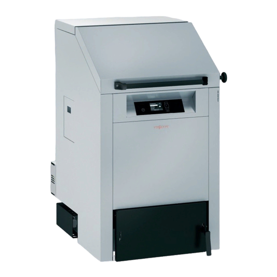
- Page 1 Viesmann Operating instructions for the system user High performance wood gasification boiler for split logs up to 50 cm long VITOLIGNO 300-S Please keep safe. 5817504 GB 7/2020...
-
Page 2: For Your Safety
Safety instructions For your safety Please follow these safety instruc- tions closely to prevent accidents and material losses. Safety instructions explained Danger Note This symbol warns against the risk Details identified by the word "Note" of injury. contain additional information. Please note This symbol warns against the risk of material losses and environmen-... -
Page 3: Auxiliary Components, Spare And Wearing Parts
Safety instructions For your safety (cont.) Work on the appliance All settings and work on the appliance Auxiliary components, spare and ■ must be carried out as specified in wearing parts these operating instructions. Please note Further work on the appliance may be Components not tested with the carried out only by authorised contrac- heating system may damage the... - Page 4 Safety instructions For your safety (cont.) If the heating system develops a fault Please note Incorrect ambient conditions can Danger lead to heating system damage and Fault messages indicate faults in can put safe operation at risk. the heating system. If faults are not Ensure ambient temperatures are ■...
- Page 5 Index Index 1. Introductory information Symbols ....................Terminology ................... Intended use ..................Commissioning ..................Your system is preset ................Energy saving tips ................. 10 Appliance description ................10 2. About the controls Control unit controls and display elements ..........12 3.
- Page 6 Index Index Changing the "Holiday program" ............33 ■ Terminating the "Holiday program" ............. 33 ■ 7. DHW heating DHW temperature .................. 34 Required settings ................34 ■ Setting the DHW temperature ............34 ■ Operating program ................. 34 Setting the operating program for DHW heating ........ 34 ■...
- Page 7 Index Index (cont.) Cleaning the heat exchanger ..............51 Emptying the heat exchanger ash pan ..........52 Cleaning the sight glass ................. 52 Cleaning the combustion chamber ............53 13. Ordering fuel Wood fuel constituents ................54 Influence of the moisture content ............54 ■...
-
Page 8: Intended Use
Introductory information Symbols Symbol Meaning Reference to other document containing further information Step in a diagram: The numbers correspond to the order in which the steps are carried out. Warning of material losses and environ- mental pollution Live electrical area Pay particular attention. -
Page 9: Introductory Information
Introductory information Intended use (cont.) Incorrect usage or operation of the appliance (e.g. the appliance being operated for longer periods when open) is prohibited and will result in an exclusion of lia- bility. Incorrect usage also occurs if the components in the heating system are modified from their intended use (e.g. -
Page 10: Appliance Description
■ requires less energy than a full bath. Appliance description The Vitoligno 300-S is suitable for the combustion of Note logs with a moisture content of 15 to 20 %, as well as If the moisture content is greater than 20 %, this can... - Page 11 Introductory information Appliance description (cont.) Overview of components Fig. 2 Heat exchanger cleaning cover Flue gas collector chamber Lifting eye/sight glass Secondary air chamber Hopper cover Ignition Hopper Ash pan Combustion chamber maintenance cover Ash chamber Combustion chamber Primary air damper Flue gas fan Ash door Cleaning door for flue gas collector chamber and...
- Page 12 About the controls Control unit controls and display elements The programming unit You can adjust all control unit settings centrally at the programming unit. Accum. extraction Boiler Cylinder Heating Select with Fig. 3 Takes you to the previous step in the menu or can- Calls up the help text relevant to the selected cels a setting that has been started.
-
Page 13: Load Operation
Start-up/shutdown Boiler operating phases The operating phases are shown on the programming ■ Residual heat utilisation unit display. After heat up, the boiler runs through the ■ Buffer drawing following operating phases in sequence: Additional heat generator (if installed) ■ Heat up ■... - Page 14 Start-up/shutdown Heat-up preparations 2. Check that the vent in the installation room is unre- stricted. Note The combustion air is drawn from the installation room during operation. 3. Check that the heating system or the heating water buffer cylinder can draw off heat. Where neces- sary, open the thermostatic valves.
-
Page 15: Heat-Up Preparations
Start-up/shutdown Heat-up preparations (cont.) Opening the hopper cover Danger 1. Initially open the hopper cover to lock Deflagration and poisonous flue gases can cause serious injuries. 2. Turn mushroom handle to unlock the hopper Never open the hopper cover in any operating cover and fully open the cover. - Page 16 Start-up/shutdown Heat-up preparations (cont.) Please note If the logs are too big, they will impair the function of the boiler and may result in poorer combustion. Take the depth of the hopper and size of the hopper cover into account when selecting logs.
- Page 17 Start-up/shutdown Heat-up (cont.) Heating up manually 3. Switch the boiler on at the control unit. Press "START/STOP". 4. Use to select "Manual". 5. Press to confirm. 6. Do not completely close the ash door; leave it approx. 10 cm ajar. 7.
- Page 18 Start-up/shutdown Heat-up (cont.) 2. Fill the lighter basket with primary ignition material (paper). 3. Close the ash door. 4. Press "START/STOP" on the programming unit. 5. Use to select "Immediately", "Automatic" or "Holiday program". 6. Press to confirm. Note If you make no selection after pressing "START", "Automatic"...
- Page 19 Note Never make adjustments at the high limit safety cut-out or thermally activated safety valve, which would result in an exclusion of liability. Replace faulty components only with genuine spare parts from Viessmann. Boiler water temperature has reached 100 °C...
- Page 20 Start-up/shutdown Measures to be carried out in the event of the… (cont.) High limit safety cut-out (STB) The high limit safety cut-out is part of the boiler. It is 1. Slide the cover on the programming unit to the located behind the programming unit under the front right.
- Page 21 Start-up/shutdown Measures to be carried out in the event of the… (cont.) Manufacturer's documentation for thermally acti- Resetting the function: vated safety valve Note Note The function is reset automatically if the boiler water A contractor must check the thermally activated safety temperature has dropped.
-
Page 22: Menu Structure Of The Control Unit
Control unit operation Navigation in the control unit menu Buffer drawing Boiler Buffer Heating Select with Fig. 12 Display of operating phase Confirms your selection or saves the setting Dialogue line made. Takes you to the previous step in the menu or can- Calls up the help text relevant to the selected cels a setting that has been started. -
Page 23: Control Unit Operation
Control unit operation Menu structure of the control unit (cont.) Extended menu Menu Boiler Heating Information Select with Fig. 14 In the extended menu, you can call up and adjust the Call up the extended menu as follows: settings of the control unit's range of less frequently From anywhere in the menu: ■... -
Page 24: Screen Saver
Control unit operation Menu structure of the control unit (cont.) Example: Procedure for settings with different dialogue lines Boiler water temp 48°C Heating Additional boiler Information Select with Heating circuit 1 Heating circuit selection Ù Ú Ù Ú Ù Ú Set room temperature Ú... - Page 25 Setting automatic ignition Setting the enable times for ignition By entering the required time phases, you enable the You can enter up to 4 time phases. electric ignition system for these periods. The boiler can only start the electric ignition system during these periods.
-
Page 26: Required Settings
Central heating Room temperature Required settings If you require central heating, check the following Have you selected the correct operating program? ■ points: For settings, see page 27. ■ Have you selected the heating circuit? ■ Have you selected the required time program? For settings, see page 26. -
Page 27: Room Temperature
Central heating Room temperature (cont.) Press the following buttons: for "Set red room temp". for the "Extended menu". to confirm. å to select "Heating". for the required temperature. to confirm. to confirm. "Adopted" appears briefly on the display. to select "Heating circuit 1" (HC1), "Heat- Ù... -
Page 28: Setting Time Phases
Central heating Time program (cont.) Please note when setting the switching times: Your Note heating system requires some time to heat the rooms For the duration of the specified switching times, the to the required temperature. relevant heating circuit is regulated to the set standard room temperature. -
Page 29: Central Heating
Central heating Heating curve Adjusting the heating curves You can alter the heating characteristics if the room Changing the slope and level ■ temperature does not meet your requirements for any prolonged period of time. Please use the following table as an aid to making ■... -
Page 30: Stopping The Central Heating
Central heating Heating curve (cont.) Note The illustrated heating curves apply with the following Setting the heating curve slope or level too high or too settings: low will not result in damage to your heating system. Heating curve level = 0 ■... - Page 31 Central heating Comfort function "Party mode" With this comfort function you can change the room ■ The rooms are heated to the required temperature. temperature of a heating circuit for a few hours, e.g. if you have guests staying until late in the evening. You do not have to change any existing control settings for this.
- Page 32 Central heating Energy saving function "Economy mode" (cont.) For "Heating". Heating circuit 1 Ù Ú To confirm. Set room temp. Heating program to select "Heating circuit 1" (HC1), "Heat- Ù Ú â Party mode ing circuit 2" (HC2), "Heating circuit 3" (HC3) or "Heating circuit 4"...
- Page 33 Central heating Energy saving function "Holiday program" (cont.) To confirm. To set the required date. to select "Heating circuit 1" (HC1), "Heat- To confirm. Ù Ú ing circuit 2" (HC2), "Heating circuit 3" "Adopted" appears briefly on the display. (HC3) or "Heating circuit 4" (HC4). For return date.
- Page 34 DHW heating DHW temperature Required settings If you require DHW heating, check the following points: Have you selected the correct operating program? ■ ■ Have you selected the required set DHW tempera- For settings, see page 34. ture? ■ Have you selected the required time program? For settings, see page 34.
-
Page 35: Stopping Dhw Heating
DHW heating Time program (cont.) Setting time phases Press the following keys: To set the end time. For the "Extended menu". To confirm. å For "DHW". 16. To set the beginning and end of further time pha- ses, proceed as described in steps 10 to 15. To confirm. - Page 36 DHW heating Stopping DHW heating (cont.) For "Operating program". For "Standby mode". To confirm. To confirm.
-
Page 37: Setting The Display Contrast
Further adjustments Setting the display contrast Press the following keys: For "Contrast". For the "Extended menu". To confirm. å For "Settings". For the required contrast. To confirm. To confirm. Setting the brightness of the display To improve the readability of the text in the menu, you For "Brightness". -
Page 38: Language Selection
Further adjustments Setting the time and date The time and date are factory-set. If your heating sys- For "Time / Date". tem has been shut down for a long time, it may be nec- essary to set the time and date. To confirm. -
Page 39: Setting The Minimum System Temperature
Further adjustments Adjusting the set value for residual oxygen Only change this setting after consulting a heating con- To confirm. tractor. You can also have the set value adjusted by your heating contractor. For "Flue gas residual O2". Press the following keys: To confirm. -
Page 40: Calling Up Information
Information call up Calling up information You can call up information in the standard menu and in the extended menu. They differ in the extent of the infor- mation displayed. If you call up the "Heating" sub-menu, you can scan information on the required heating circuit via " ". - Page 41 Information call up Calling up temperatures Information on temperatures can be called up via the standard menu and the extended menu. The range of dis- played values is wider in the extended menu. We therefore recommend calling up temperatures via the extended menu.
- Page 42 Information call up Calling up fault messages Displaying a fault message If any faults have occurred in your heating system, the This can reduce the time required to resolve the fault " " symbol flashes on the display and "Fault" is and save costs.
- Page 43 Prolonged heating system shutdown Prolonged heating system shutdown If you do not intend using your heating system for a Note while, you can switch it off. We recommend you con- No special measures are required for a temporary sys- tact your heating contractor before and after shutting tem shutdown.
-
Page 44: Rooms Are Too Cold
What to do if... Rooms are too cold Cause Remedy Central heating is switched off. Check the room thermostats. If necessary, change the operating program. Control unit incorrectly set. Check the settings and correct if required: Heating circuit must be switched on; see page 27 ■... -
Page 45: There Is No Hot Water
What to do if... There is no hot water Cause Remedy Control unit incorrectly set. Check the settings and correct if required: DHW heating must be switched on; see page 34 ■ DHW temperature; see page 34 ■ Time; see page 38 ■... -
Page 46: Replacing Fuses
Maintenance Heating system inspection and maintenance Inspection and maintenance of heating systems is Regular maintenance ensures trouble-free, energy effi- compulsory acc. to the Energy Saving Ordinance [Ger- cient and environmentally responsible heating opera- tion. In this regard, we recommend arranging an many], EN 806 and DIN 1988-8 ( : ÖNORM B 8131) [or local regulations]. -
Page 47: Maintenance
Maintenance Overview of maintenance and cleaning work Fig. 38 Heat exchanger cleaning cover Flue gas collector chamber Lifting eye/sight glass Secondary air chamber Hopper cover Ignition Hopper Ash pan Combustion chamber maintenance cover Ash chamber Combustion chamber Primary air damper Flue gas fan Ash door Cleaning door for flue gas collector chamber and... - Page 48 Maintenance Overview of maintenance and cleaning work (cont.) Interval Activity System Heating con- page users tractors After 900 hours run, and at least once a year Cleaning flue gas fan Cleaning the Lambda probe Checking gaskets and seals Check hopper cover , cleaning door and ash door for leaks...
- Page 49 Maintenance Information regarding maintenance and cleaning (cont.) Danger Note Wood dust, ash and soot pose a danger to the ■ Only clean the boiler with the cleaning equipment respiratory tract during cleaning work and when provided and an ash vacuum cleaner. Never use manipulating the ash box.
- Page 50 Maintenance Hopper cleaning (if required) 2. Use a scraper or spatula to remove dry and flaking deposits (ash, carbon and tar) from the hopper walls and the inside of the hopper cover. Note ■ Small surface cracks in moulded refractory con- crete parts are normal.
-
Page 51: Cleaning The Heat Exchanger
Maintenance Cleaning the heat exchanger Fig. 41 01. Remove the casing panel and thermal insulation. 06. Undo all screws in the maintenance cover behind this and remove the maintenance cover. 02. Undo the star knob and pivot the cleaning cover open until the lock clicks into place. - Page 52 Maintenance Emptying the heat exchanger ash pan 1. Open the cleaning door using the hand knob. 2. Empty the ash pan. 3. Clean the flue gas collector chamber and secon- dary air chamber with a scraper or vacuum cleaner. 4. Check the gaskets for wear and damage. Replace the gaskets if necessary.
-
Page 53: Cleaning The Combustion Chamber
Maintenance Cleaning the combustion chamber Fig. 44 1. Remove the casing panel from the combustion 6. Open the ash door. chamber maintenance cover. 7. Empty the ash pan and clean the ash chamber 2. Undo all screws in the maintenance cover behind with a scraper or vacuum cleaner. - Page 54 When procuring wood for combustion in a The values must not exceed or fall below the following Vitoligno 300-S, ensure that foreign objects (e.g. limits (per kg of dry fuel) for the non-combustible con- stones, metal parts, pieces of brick, plastics, etc.) are tent (ash at an analysis temperature of 815 °C):...
- Page 55 Ordering fuel Approved logs For combustion in the Vitoligno 300-S, the following requirements apply for logs, such as split or round logs: To EN ISO 17225-5 Additional details Property class – Diameter Hardwood: 5 to 15 cm ■ Softwood: 5 to 12 cm ■...
- Page 56 Appendix Terminology Setback mode (reduced heating mode) Standard room temperature See "Reduced heating mode". For periods when you will be at home during the day, select the standard room temperature. Extension kit for heating circuit with mixer Open flue operation Assembly (accessories) for controlling a heating circuit with mixer The combustion air is drawn from the room where the...
-
Page 57: Final Decommissioning And Disposal Of The Heating System
(Altstoff Recycling Austria AG, licence num- ber 5766). Final decommissioning and disposal of the heating system Viessmann products can be recycled. Components and fluids from your heating systems are not part of ordinary domestic waste. Please speak to your contractor about the correct dis- posal of your old system. - Page 58 Keyword index Keyword index Display Activating – Contrast setting............37 – Comfort function............31 – Language selection..........38 Actual temperature.............56 – Setting the brightness..........37 Additional information on selected menu....23 Display backlighting........... 37 Drinking water filter..........46, 56 Boiler – Components............11 Economy mode............
- Page 59 Keyword index Keyword index (cont.) Heating system, starting..........14 Heating times, changing..........28 Open flue operation............56 Heating up Operating program – Manual..............17 – DHW heating............34 Heating water buffer cylinder – Selecting for central heating........27 – Temperature call up..........41 Heat-up..............16 – Preparations............14 Party mode –...
-
Page 60: Keyword Index
Your contact Contact your local contractor if you have any questions about your system or wish to arrange maintenance or repair work. You can find local contractors on the internet at www.viessmann.de. Viessmann Werke GmbH & Co. KG Viessmann Limited...