Viessmann VITOLIGNO 300-H Operating Instructions For The System User
Heating system with ecotronic weather-compensated, digital boiler and heating circuit control unit
Hide thumbs
Also See for VITOLIGNO 300-H:

Related Manuals for Viessmann VITOLIGNO 300-H


Summary of Contents for Viessmann VITOLIGNO 300-H
- Page 1 VIESMANN Operating instructions for the system user Heating system with Ecotronic weather-compensated, digital boiler and heating circuit control unit VITOLIGNO 300-H Please keep safe. 5549 811 GB 9/2014...
- Page 2 Safety instructions For your safety Please follow these safety instructions closely to prevent accidents and mate- rial losses. Safety instructions explained Appliance connection Danger ■ The appliance may only be connected This symbol warns against the and commissioned by authorised con- risk of injury.
- Page 3 Safety instructions For your safety (cont.) If you smell flue gas Conditions for siting Danger Danger Flue gas can lead to life threat- Sealed vents result in a lack of ening poisoning. combustion air. This leads to ■ Shut down the heating system. incomplete combustion and the ■...
- Page 4 Safety instructions For your safety (cont.) Extractors The operation of appliances that extract air to the outside (cooker hoods, extrac- tors, air conditioning units, etc.) can cre- ate vacuum pressure. If the boiler is operated at the same time, this can lead to reverse flow of the flue gas.
-
Page 5: Table Of Contents
Index Index Introductory information Intended use......................Commissioning..................... Your system is preset at the factory..............Terminology......................10 Energy saving tips....................10 Where to find the controls Boiler controls and components................11 Controls and display elements of control unit............12 Boiler operation Heat-up preparations.................... - Page 6 Index Index Setting the time program..................36 ■ Setting time phases..................36 ■ Deleting a time phase..................37 ■ Resetting time phases to factory settings............37 Stopping DHW heating..................38 Heating water buffer cylinder Selecting the operating program................39 Setting the time program..................40 ■...
- Page 7 Index Index (cont.) The DHW is too hot....................58 "Fault" is shown in the display................58 Ordering fuel....................... 59 Maintenance and cleaning Care, inspection and maintenance............... 60 Replacing fuses....................61 Cleaning information.................... 61 Maintenance intervals..................61 Emptying the ash box................... 62 Cleaning the light barriers..................
-
Page 8: Introductory Information
Introductory information Intended use The appliance is only intended to be Any usage beyond this must be installed and operated in sealed unven- approved by the manufacturer in each ted heating systems that comply with individual case. EN 12828, with due attention paid to the associated installation, service and Incorrect usage or operation of the appli- operating instructions. -
Page 9: Your System Is Preset At The Factory
Introductory information Your system is preset at the factory Your boiler's control unit is set at the fac- Frost protection tory. ■ Your boiler, DHW cylinder and heating ■ The heating circuits are set to the water buffer cylinder are protected "Heating"... -
Page 10: Terminology
Introductory information Terminology The appendix contains a chapter entitled "Terminology" to provide you with a bet- ter understanding of the functions of your boiler. Energy saving tips Use the adjustment options offered by Contact your heating contractor for addi- your boiler control unit: tional energy saving functions offered by ■... -
Page 11: Where To Find The Controls
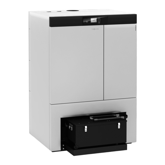
Where to find the controls Boiler controls and components A Programming unit of the control C Front door unit D Ash box B Reset button for high limit safety cut- out behind the casing Note You will find an overview of the cleaning and maintenance tasks from page 60. -
Page 12: Controls And Display Elements Of Control Unit
Where to find the controls Controls and display elements of control unit The programming unit Danger The programming unit is mounted on the There is a risk of falling due to front at the top, above the front door. slipping and tripping on the ash box. -
Page 13: Boiler Operation
Action in case of overheating The high limit safety cut-out protects Note your boiler from overheating. Modifications to these components, of any kind whatsoever, are prohibited and will render all warranties void. Replace faulty components only with genuine spare parts from Viessmann. -
Page 14: Boiler Water Temperature Has Reached 95 °C
Boiler operation Action in case of overheating (cont.) Note If the boiler overheats again after a short time or overheats regularly, notify your heating contractor. Boiler water temperature has reached 95 °C High limit safety cut-out The reset button of high limit safety cut- Cancelling the function out A is located behind the boiler cas- ing. - Page 15 Boiler operation Action in case of overheating (cont.) 1. Open the front door. 2. Press green button A of the high limit safety cut-out. You will hear a faint "click". The high limit safety cut- out has been reset. 3. Close the front door. 4.
-
Page 16: Control Unit Operation
Control unit operation Navigation in the control unit menu Buffer drawing Boiler Buffer Heating Select with A Display of operating phase d Confirms your selection or saves B Dialogue line the setting. Calls up the help text relevant to the Takes you to the previous step in selected menu point. - Page 17 Control unit operation Navigation in the control unit menu (cont.) Example: Procedure for settings with different dialogue lines 48°C Boiler water temp Heating Additional boiler Information Select with Heating circuit 1 Heating circuit selection Ù Ú Ù Ú Ù Ú Set room temperature Ú...
-
Page 18: Menu Structure Of The Control Unit
Control unit operation Menu structure of the control unit There are 2 control levels available, the "Standard menu" and the "Extended menu". Standard menu Buffer drawing Boiler Buffer Heating Select with You can call up the settings you require ■ Calling up information most frequently from the standard ■... - Page 19 Control unit operation Menu structure of the control unit (cont.) Extended menu Menu Boiler Charging Buffer Heating Select with In the extended settings menu, you can Call up the extended menu as follows: call up and adjust the settings of the con- ■...
- Page 20 Control unit operation Menu structure of the control unit (cont.) Screensaver during operating phase "Boiler load operation" Boiler load operation 56°C 73°C Flue gas 135°C Overview Boiler A Boiler flow temperature E Dialogue line B Operating phase F Heating output of the boiler C Boiler return temperature G Feed pump rate D Flue gas temperature...
- Page 21 Control unit operation Menu structure of the control unit (cont.) Press any key. This takes you to the standard menu (see page 16). "Help" menu You can view an abridged guide giving an explanation of the controls and infor- mation about heating circuit selection. Call up the short guide as follows: ■...
-
Page 22: Central Heating
Central heating Required settings If you require central heating, check the ■ Have you selected the correct operat- following points: ing program? ■ Have you selected the heating circuit? For settings, see page 24. For setting, see chapter "Selecting a ■... -
Page 23: Setting The Room Temperature
Central heating Setting the room temperature You can set the standard room temper- Set room temperature for reduced ature (for day) and the reduced room heating mode (night setback) temperature (for night) for the relevant heating circuit. Heating circuit 1 ■... -
Page 24: Setting The Operating Program
Central heating Setting the operating program Check if "Heating" is set for the relevant 4. Ù/Ú to select "Heating circuit 1" heating circuit. (HC1), "Heating circuit 2" (HC2), "Heating circuit 3" (HC3) or "Heating cir- Heating circuit 1 cuit 4" (HC4, if installed). Set room temp. -
Page 25: Setting Switching Times
Central heating Setting a time program (cont.) ■ You can set switching times individu- Please note when setting the switching ally for the following days or parts of times: Your heating system requires the week: some time to heat the rooms to the –... -
Page 26: Deleting A Time Phase
Central heating Setting a time program (cont.) 12. d to confirm. 15. To adjust the beginning and end of further time phases, proceed as 13. |/~ to set the end time. described in steps 9 to 14. 14. d to confirm. Deleting a time phase 1. - Page 27 Central heating Changing the heating curve (cont.) Heating characteristics Measures Example The living space is too cold Adjust the heating curve Slope during the heating sea- slope to the next high- Level son. est value (e.g. 1.5). The living space is too hot Adjust the heating curve Slope during the heating sea-...
- Page 28 Central heating Changing the heating curve (cont.) 9. |/~ for the required value. The illustrated heating curves apply with the following settings: Heating curve ■ Heating curve level = 0 100°C Different level settings shift the curve 81°C 23°C 68°C in parallel in a vertical direction.
- Page 29 Central heating Changing the heating curve (cont.) Slope Outside temperature in °C Example for outside temperature −14 °C: A Underfloor heating system, slope 0.2 to 0.8 B Low temperature heating system, slope 0.8 to 1.6 C Heating system with a boiler water temperature in excess of 75 °C, slope 1.6 to 2.0...
-
Page 30: Stopping Central Heating
Central heating Stopping central heating Heating program Heating Standby mode Select with Press the following keys: 1. ä repeatedly until the standard menu is displayed. 2. |/~ for "Heating". 3. d to confirm. 4. Ù/Ú to select "Heating circuit 1" (HC1), "Heating circuit 2"... -
Page 31: Comfort And Energy Saving Functions
Comfort and energy saving functions Selecting party mode With this comfort function, you can 7. |/~ for the required temperature, change the room temperature of a heat- if you want to change the ing circuit for a few hours, e.g. if guests value. -
Page 32: Selecting Economy Mode
Comfort and energy saving functions Selecting party mode (cont.) 6. d to confirm. "Off" appears briefly in the dialogue line of the display. "Off" appears on the right- hand side of the display in the following menu. Selecting economy mode To save energy, you can reduce the 4. -
Page 33: Selecting The Holiday Program
Comfort and energy saving functions Selecting economy mode (cont.) 6. d 4. Ù/Ú to select "Heating circuit 1" to confirm. (HC1), "Heating circuit 2" In the display "Economy (HC2), "Heating circuit 3" mode Off" appears briefly. (HC3) or "Heating cir- "Off"... - Page 34 Comfort and energy saving functions Selecting the holiday program (cont.) 10. d 8. d to confirm. to confirm. "Adopted" appears briefly in the display. 9. |/~ for "Yes". 11. |/~ for return date. 10. d to confirm. "Adopted" appears briefly 12.
-
Page 35: Dhw Heating
DHW heating Required settings If you want DHW heating, check the fol- ■ Have you selected the required time lowing points: program? ■ Have you selected the required set For settings, see page 36. DHW temperature? For settings, see page 35. ■... -
Page 36: Setting The Time Program
DHW heating Setting the operating program (cont.) 6. |/~ for "DHW" or "Standby mode". 7. d to confirm. Setting the time program When DHW heating is enabled for the ■ If you don't require automatic mode, heating circuit depends on the settings of you can select up to 4 individual time the switching times for the respective phases per day for DHW heating. -
Page 37: Deleting A Time Phase
DHW heating Setting the time program (cont.) Example shown: Example: ■ Time program for Monday to Friday You want to set the same time program ("Mo-Fr") for every day except Monday: ■ Time phase !: Select the period "Monday–Sunday" and set the time program. From 04:30 to 06:30 h ■... -
Page 38: Stopping Dhw Heating
DHW heating Stopping DHW heating Press the following keys: 1. ä repeatedly until the standard menu is displayed. 2. |/~ for "DHW". 3. d to confirm. 4. |/~ for "Operating program". 5. d to confirm. 6. |/~ for "Standby mode". 7. -
Page 39: Heating Water Buffer Cylinder
Heating water buffer cylinder Selecting the operating program 3. d There are 3 operating programs availa- to confirm. ble for controlling the heating water tem- peratures in the heating water buffer cyl- 4. |/~ for "Operating program". inder: ■ "Automatic" 5. -
Page 40: Setting The Time Program
Heating water buffer cylinder Setting the time program You can set these heating times by Note adjusting the time program for the heat- If your are using a solar thermal system ing water buffer cylinder. During the time for central heating backup, the heating phases set, the heat-up condition of the times of the heating water buffer cylinder heating water buffer cylinder has an... -
Page 41: Deleting A Time Phase
Heating water buffer cylinder Setting the time program (cont.) 12. |/~ to set the start time. Example shown: ■ Time program for Monday to Friday 13. d to confirm. ("Mo-Fr") ■ Time phase !: 14. |/~ to set the end time. From 04:30 to 08:30 h ■... - Page 42 Heating water buffer cylinder Setting the heating curve (cont.) 7. d to confirm. 8. |/~ for the required value. Heating curve 100°C 81°C 60°C 75°C 70°C 65°C Slope Change with 9. d to confirm.
-
Page 43: Fuel Supply
Fuel supply Blocking times for automatic fuel supply If you only want the pellet hopper to be Note charged at certain times, you can select Only adjust the blocking times for the fuel the blocking times individually. supply if pellet supply takes place via a Select the times to ensure that there is vacuum module. -
Page 44: Deleting Blocking Times
Fuel supply Blocking times for automatic fuel supply (cont.) Deleting blocking times 1. Set the time for the end point to the same time that was set for the start point. The display shows "- - : - -". 2. Press d to confirm. Mo-Fr 8 10 12 14 16 18 20 22 24 - -:- - - - -:- -... -
Page 45: Further Adjustments
Further adjustments Setting the display contrast Press the following keys: 4. |/~ for "Contrast". 1. å for the "Extended menu". 5. d to confirm. 2. |/~ for "Settings". 6. |/~ for the required contrast. 3. d to confirm. 7. d to confirm. -
Page 46: Setting The Time And Date
Further adjustments Naming heating circuits (cont.) Heating circuit 1 6. |/~ to select "Heating cir- cuit 1" (HC1), "Heating cir- cuit 2" (HC2), "Heating cir- Apartment cuit 3" (HC3) or "Heating circuit 4" (HC4, if instal- Adopted led). 7. d to confirm. -
Page 47: Language Selection
Further adjustments Setting the time and date (cont.) 9. d 8. |/~ for the required time or the to confirm. required date. Language selection Press the following keys: 4. |/~ for "Language". 1. å for the "Extended menu". 5. d to confirm. -
Page 48: Changing The Set Value Of Residual Oxygen
Further adjustments Changing boiler water temperature (cont.) 4. |/~ for "Boiler temperature". 6. |/~ for the required temperature. 5. d to confirm. 7. d to confirm. Changing the set value of residual oxygen Only change this setting after consulting 3. d to confirm. -
Page 49: Restoring Factory Settings
Further adjustments Restoring factory settings You can individually restore all modified values for each heating circuit to their factory setting. Press the following keys: 1. å for the "Extended menu". 2. |/~ for "Settings". 3. d to confirm. 4. |/~ for "Standard setting". 5. -
Page 50: Scanning
Scanning Scanning fault messages If any faults have occurred in your heat- 1. You can call up the cause of the fault ing system, the symbol " " flashes on with d. the display and "Fault" is shown. The heating contractor uses fault mes- Fault sages to quickly pinpoint the cause of Outside temp sensor... -
Page 51: Scanning Information
Scanning Scanning fault messages (cont.) 3. Make a note of the cause of the fault Calling up an acknowledged fault and the fault code next to it on the message right. In this example: "Outside sen- sor 34" and "Fault O2 probe 91". Press the following keys: This enables the heating contractor to be better prepared for the service call... - Page 52 Scanning Scanning information (cont.) Scanning information in the standard Scanning information in the extended menu menu Press the following keys: Press the following keys: 1. ä repeatedly until the standard 1. å for the "Extended menu". menu is displayed. 2. |/~ for "Information". 2.
-
Page 53: Scanning Temperatures
Scanning Scanning information (cont.) ■ "Heating" sub-menu: – Heating circuit pump – Operating program – Valve – Operating status ■ "DHW" sub-menu: – Time program – Operating program – Set room temp – Operating status – Set reduced room temperature –... - Page 54 Scanning Scanning information (cont.) The following temperatures can be scan- ■ Set return temperature ned in the "Buffer" menu: ■ Actual return temperature ■ Set buffer ■ Buffer average ■ Buffer sensors Scanning temperatures in the exten- ded menu Press the following keys: 1.
-
Page 55: Shutting Down The Heating System For An Extended Period
Shutting down the heating system for an extended period Shutting down the heating system for an extended period You can switch your heating system OFF Note if you do not intend using it. We recom- No special measures are necessary mend you contact your local heating con- when shutting down the system on a tractor before and after shutting down for... -
Page 56: What To Do If
What to do if... Rooms are too cold Cause Remedy Central heating is switched off. Check the room thermostats. If necessa- ry, change the operating program. Control unit incorrectly set. Check the settings and correct if required: ■ The heating circuit must be on (see page 24) ■... -
Page 57: Rooms Are Too Hot
What to do if... Rooms are too hot Cause Remedy Control unit incorrectly set. Check the settings and correct if required: ■ The heating circuit must be on (see page 24) ■ Room temperature (see page 24) ■ Time (see page 46) ■... -
Page 58: There Is No Hot Water
What to do if... There is no hot water Cause Remedy Control unit incorrectly set. Check the settings and correct if required: ■ DHW heating must be on (see page 35) ■ DHW temperature (see page 35) ■ Time (see page 46) ■... -
Page 59: Ordering Fuel
Ordering fuel Ordering fuel Ordering wood pellets The pellets used must meet the require- Delivery methods ments of EN plus, class A1 and Pellets are sold in 15 to 30 kg sacks, in EN 14961-2, class A1 (a: ÖNORM 7135). Only use pellets with the bulk cartons up to 1000 kg and in bulk. -
Page 60: Maintenance And Cleaning
Maintenance and cleaning Care, inspection and maintenance Regular maintenance ensures trouble- Additionally, for DHW cylinder with sac- free, energy-efficient and environmen- rificial anode: tally responsible heating. For this, we We recommend that the correct function strongly advise you to arrange an of the sacrificial anode is checked annu- inspection and maintenance contract ally by your heating contractor. -
Page 61: Replacing Fuses
Maintenance and cleaning Replacing fuses Danger Only a heating contractor may Contact with 'live' components of replace fuses. the control unit can lead to fatal injury due to electric shock. Cleaning information Have a heating contractor clean the inte- Danger rior of the boiler once a year. -
Page 62: Emptying The Ash Box
Maintenance and cleaning Maintenance intervals (cont.) Vitoligno 300-H System user Heating contrac- Every 7 days Check the fill level of the ash box and empty it if required. Visually inspect the light barriers and clean them if required. Emptying the ash box... -
Page 63: Cleaning The Light Barriers
Maintenance and cleaning Emptying the ash box (cont.) Danger 4. Empty the ash box. Severe burns due to hot sur- faces 5. Proceed in reverse order to insert the Only perform cleaning work ash box and close the boiler. when the boiler is cold. Note Switch off the boiler. -
Page 64: Appendix Terminology
Appendix Terminology Setback mode (reduced heating The water brought to the right tempera- mode) ture is pumped to the heating circuit by the heating circuit pump. The control unit See "Reduced heating mode". adjusts the heating circuit flow tempera- ture via the mixer to suit different condi- Extension kit for heating circuit with tions. -
Page 65: Efficient And Clean Operation
Appendix Terminology (cont.) Reduced room temperature Drinking water filter For periods when you will be absent or A device that removes solids from pota- during the night, select the reduced room ble water. The drinking water filter is temperature. Set the periods using the installed in the cold water pipe upstream time program for central heating. -
Page 66: Dismantling And Disposal
Appendix Efficient and clean operation (cont.) ■ Your boiler can be controlled within a range of 30 to 100 % of its rated heat- ing output. To avoid unnecessary emissions in low load operation, the appliances should be operated in the middle and upper output range (adjus- ted to the relevant heat demand) if possible. -
Page 67: Energy Saving Tips
Energy saving tips Energy saving tips You can also save energy by taking the following steps: ■ Correct ventilation/airing: Open windows A wide for a short time. During this time, close thermo- static valves B. ■ Do not overheat the rooms; aim for a room temperature of 20 °C. -
Page 68: Keyword Index
Keyword index Keyword index DHW heating Actual temperature......64 – Factory setting........9 Ash box emptying......62 – Operating program......35 – Setting the temperature....35 – Starting...........35 Boiler – Time phases........36 – Boiler water temperature change. . .47 – Time program.........36 – Controls and components....11 DHW temperature setting....35 –... - Page 69 Keyword index Keyword index (cont.) Heating circuit pump......64 Heating circuit selection.....22 Menu Heating circuit with mixer....64 – Extended menu......19 Heating curve – Help..........21 – Explanation........28 – Selection.........16 – Level, changing......26 – Standard menu.......18 – Slope, changing......26 – Structure.........18 Heating mode Messages –...
- Page 70 Keyword index Keyword index (cont.) Room temperature – Reduced.........65 Temperature – Standard.........64 – Actual temperature......64 Room temperature changing.....23 – Change...........23 – DHW..........35 – Scanning.........51 Safety valve........65 – Set temperature......65 Safety valve (DHW cylinder)....60 Temperature unit........47 Scan Time...........46 – Fault message........50 Time/date –...
- Page 72 Contact your local contractor if you have any questions regarding the maintenance and repair of your system. You may, for example, find local contractors on the internet under www.viessmann.com. Viessmann Werke GmbH&Co KG Viessmann Limited D-35107 Allendorf Hortonwood 30, Telford...