Table of Contents
Advertisement
Quick Links
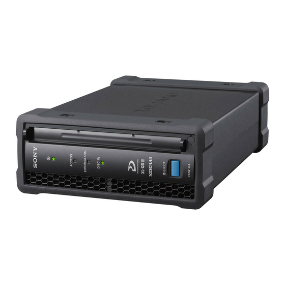
PROFESSIONAL DISC DRIVE UNIT
PDW-U4
利用条件:
① 本情報はソニー製品の販売,設置,設定,使用の目的でのみご利用ください。かかる
目的以外での利用を禁止します。
② 著作者の事前の書面による許可なく,本情報の全部または一部の複写,複製,転載,
改変,翻訳,送信等を禁止します。
情報改訂:
本情報は,当社の裁量により,予告なく変更されることがあります。ご使用される場合,
本情報が最新の情報であることを確認のうえ,ご使用ください。
Conditions of Use:
(1) Please use this information only for the purpose of sales, installation, configuration,
and use of Sony products. Using this information for any purpose other than the purpose
described foregoing is forbidden.
(2) Do not copy, replicate, reproduce, alter, translate, transmit, sell, lease, or distribute this
information in whole or in part without the prior written permission of the author.
Revision of Information:
This information may be changed or updated at any time without any prior notice. Please
confirm that this information is up-to-date before using it.
SERVICE MANUAL
1st Edition
Advertisement
Table of Contents

Related Manuals for Sony PDW-U4


Summary of Contents for Sony PDW-U4
- Page 1 Conditions of Use: (1) Please use this information only for the purpose of sales, installation, configuration, and use of Sony products. Using this information for any purpose other than the purpose described foregoing is forbidden. (2) Do not copy, replicate, reproduce, alter, translate, transmit, sell, lease, or distribute this information in whole or in part without the prior written permission of the author.
- Page 2 警告 このマニュアルは,サービス専用です。 お客様が,このマニュアルに記載された設置や保守,点検,修理などを行うと感電や火災, 人身事故につながることがあります。 危険をさけるため,サービストレーニングを受けた技術者のみご使用ください。 WARNING This manual is intended for qualified service personnel only. To reduce the risk of electric shock, fire or injury, do not perform any servicing other than that contained in the operating instructions unless you are qualified to do so. Refer all servicing to qualified service personnel.
- Page 3 When installing the installation space must be secured Laser Diode Properties in consideration of the ventilation and service operation. Wavelength : 400 to 410 nm . Do not block the ventilation slots and vents of the fans. Emission duration : Continuous .
-
Page 4: Table Of Contents
Table of Contents Section 1 Service Overview ....................5 1-1. Operating Environment ........................ 5 1-2. Recommended Power Cord ......................6 1-3. Supplied Accessories ........................7 1-4. Cables ............................7 1-5. Location of Main Parts ......................... 8 1-5-1. Location of Boards and Circuit Configuration............... 8 1-5-2. - Page 5 3-2-2. Error 20 ..........................38 3-2-3. Error 3X ..........................41 3-2-4. Error 5X ..........................44 3-2-5. Error 6X ..........................47 3-2-6. Error 91 ..........................50 3-2-7. Error 95 ..........................55 Section 4 Replacement of Main Parts .................. 63 4-1. General Information for Parts Replacement ................63 4-1-1.
- Page 6 6-4. CHECK Menu .......................... 111 6-4-1. DEVICE, TEMPERATURE SENSOR ................111 6-4-2. DEVICE, FAN MOTOR ....................112 6-4-3. DEVICE, ACCELERATION SENSOR (STATIC) ............113 6-4-4. LOADER ........................... 115 6-4-5. SLIDER ..........................120 6-4-6. SPINDLE MOTOR ......................121 6-4-7. OPTICAL BLOCK, SA ACTUATOR ................122 6-4-8.
- Page 7 Frame Wiring ..........................151 Revision History ........................152...
-
Page 8: Section 1 Service Overview
Section 1 Service Overview 1-1. Operating Environment Operating temperature 5 to 40 degrees-C Operating humidity 20 to 90 % (no condensation) Storage temperature - 20 to 60 degrees-C Prohibited installation places • Places exposed to direct sunlight or intense light •... -
Page 9: Recommended Power Cord
1-2. Recommended Power Cord This unit does not come with a power cord. (Except for CN model) To get a power cord, please contact your local Sony Sales Office/Service Center. WARNING • Use the approved Power Cord (3-core mains lead)/Appliance Connector/Plug with earthing-contacts that conforms to the safety regulations of each country if applicable. -
Page 10: Supplied Accessories
1: Power cord 250 V 2.5 A (2.0 m) 1-846-433-7x If this type of power cord is not available, purchase a power cord 1-846-103-8x. If the unit is used in the area except above, please contact your local Sony Sales Office/Service Center. 1-3. Supplied Accessories •... -
Page 11: Location Of Main Parts
1-5. Location of Main Parts 1-5-1. Location of Boards and Circuit Configuration Location No. Board Name Circuit Function BD-48 Drive main JK-109 • Power button • DC IN KY-800 Front panel LDR-35 Cartridge sensor LDR-36 Loading position sensor SE-1004A • EEPROM •... -
Page 12: Location Of Main Mechanical Parts
1-5-2. Location of Main Mechanical Parts Location No. Part Name Loader assembly Cleaner assembly Loading motor assembly Optical block assembly (OP-0) Optical block assembly (OP-1) Sled motor assembly Spindle motor DC fan (52 square) DC fan (40 square) -
Page 13: Location Of Sensors And Their Functions
1-6. Location of Sensors and Their Functions Location No. Part Name Function OP position sensor (0 side) Detects position of the optical block assembly. OP position sensor (1 side) Detects position of the optical block assembly. REC INH sensor Detects status of the recording prohibition tab of the cartridge. Cartridge DOWN sensor Detects down position of the cartridge. -
Page 14: To Eject Cartridge Manually
The fuse is essential parts for safe operation. Replace the components with Sony parts whose part numbers appear in the manual published by Sony. If the components are replaced with any parts other than the specified ones, this may cause a fire or electric shock. -
Page 15: Setting Onboard Switch
1-9. Setting Onboard Switch 1-9-1. BD-48 Board S700 S600 BD-48 Board/Side A Note Do not turn on the switches (for factory use) while power is supplied. Ref. No. Name Description System Reset Factory use Disc Drive LSI Recovery Factory use Disc Drive LSI Reboot Factory use S600... -
Page 16: Equipment And Fixtures List For Check/Adjustment
1-10. Equipment and Fixtures List for Check/Adjustment 1-10-1. Tools Part No. Name J-6325-110-A Torque driver bit (M1.4/M1.7) Tightening screws Corresponding screws: • P1.7 x 2.5 • Special head machine screw (M2 x2.7) • P2 x 2 J-6325-380-A Torque driver bit (M2.0) Tightening screws Corresponding screws: •... -
Page 17: Equipment List For Checking And Adjustment
Utility software XDCAM Drive • Firmware update, etc. For obtaining the software, – Utility • Data read check, etc. contact your local Sony Sales Office/Service Center. PDW-U1 service software Check and adjustment of drive For obtaining the software, – contact your local Sony Sales Office/Service Center. -
Page 18: Xdcam Drive Utility Software
1-11. XDCAM Drive Utility Software The installation method and starting method of the XDCAM Drive Utility Software (referred to as Utility software hereafter) are described in the Operating Instructions. -
Page 19: Cables To Handle With Care
1-12. Cables to Handle with Care 1-12-1. Disconnecting/Connecting Flexible Cable (FFC, FPC) Note • Be very careful not to fold flexible cables. Life of flexible cable will be significantly shortened if it is folded. • Each flexible cable has conductive side and insulated side. If the flexible cable is connected in the wrong orientation of the conductive side and the insulated side, the circuit will not function. -
Page 20: Disconnecting/Connecting Fine-Wire Coaxial Cable
Type D Angle of locking tab and angle of connecting-disconnecting flexible cable Locking tab Flexible cable 90˚ Locking tab (Upper and lower both sides are conductive surface.) 90˚ 0˚ to 20˚ Connector Flexible cable Type E Locking tab Angle of locking tab and angle of connecting-disconnecting flexible cable Conductive surface Locking tab... - Page 21 Disconnecting Both sides of connector Hold the connector to disconnect Correct Do not attempt to disconnect by Fine-wire coaxial cable Wrong pulling the cable. 1. Hold both sides of the fine-wire coaxial cable connector, and pull the connector in the direction of the arrow to disconnect it.
-
Page 22: Disconnecting/Connecting Power Harness
1-12-3. Disconnecting/Connecting Power Harness Disconnecting 1. Hook your nail or fingertip on the protrusion for pulling. (Fig.1) 2. Pull up the crimp socket upward to unlock the simplified lock. (Fig.2) 3. Pull up the crimp socket further to unlock the enhanced lock. (Fig.3) Crimp socket Enhanced lock Header... -
Page 23: Cautions On Handling The Optical Block Assembly
1-13. Cautions on Handling the Optical Block Assembly When handling the optical block assembly, perform grounding as described below to prevent electrostatic breakdown. Grounding human body Be sure to wear a grounded wrist strap (10 Ω or less) to discharge static electricity charged in the human body. - Page 24 Keep away a screwdriver Objective lens Actuator Hold the shaded portions.
-
Page 25: Section 2 Periodic Inspection And Maintenance
Section 2 Periodic Inspection and Maintenance This section describes periodic inspection and cleaning methods. 2-1. Periodic Inspection Inspect and replace parts regularly to maximize and maintain the performance of the unit. 2-1-1. Digital Hours Meter The operating time or the number of operation times of the unit is totalized and displayed by the Utility software. -
Page 26: Periodic Inspection And Replacement Parts List
2-1-2. Periodic Inspection and Replacement Parts List The following table does not show the guarantee period of each part. The part replacement cycle or recommended replacement time varies depending on the operating environment and the use situation. Location Part to be Hours Meter Replacement Part No. -
Page 27: Cleaning
2-2. Cleaning To maximize the functions and performance of the unit and extend the lifetime of the unit and cartridge, carry out cleaning as routine maintenance. 2-2-1. General Information for Cleaning Using Cleaning Cloth Note • Be sure to turn off the power of the unit before starting cleaning. •... -
Page 28: Cleaning The Spindle Motor
2-2-3. Cleaning the Spindle Motor Note • The optical block assembly in the drive assembly may be broken by static electricity charged in human body and clothes. Carry out proper grounding and then start cleaning. (Refer to “1-13. Cautions on Handling the Optical Block Assembly”.) •... -
Page 29: Cleaning After Operation In Special Environment
2-2-4. Cleaning after Operation in Special Environment After the unit has been used in a seaside, sandy place, humid place, or dusty place, perform the following procedure. Note Do not touch the part (slide shaft) to which oil is applied in the drive during cleaning. If oil adheres to the cleaning cloth, replace it with new one. -
Page 30: Cleaning The Pickup Lens
6. Remove dust or dirt from the front frame assembly with a cleaning cloth (or cotton swab) moistened with cleaning fluid. 7. Install the front frame assembly. 8. Install the cabinet parts. 9. Insert the cartridge and check that the DISC IN indicator lights up after the ACCESS indicator blinks. 2-2-5. -
Page 31: Section 3 Troubleshooting
Section 3 Troubleshooting 3-1. Overview of Error Indication This unit has a self-diagnosis function to detect internal errors. Displaying error When this unit detects internal errors, the ERROR/ ALARM indicator on the front panel blinks at intervals of 0.25 seconds or 1 second. Error information (error codes, etc.) can be found on the Alarm Status screen of the Utility software. -
Page 32: Error Codes
Conditions of switching off the ERROR/ALARM indicator’s blink Referring to “3-2. Error Codes”. 3-2. Error Codes An error code is displayed in combination of 2-digit main code and 3-digit sub code. XX-XXX Main code Sub code Main Code Main Error Optical drive control errors and device errors •... -
Page 33: Error 0X
3-2-1. Error 0X When an optical drive control error or a device error is detected, one of the following error codes is displayed. Main ERROR/ALARM indicator Description Error remedy method Refer to section Code Code Lighting Switching off interval condition 1 second Disc/Power Optical block assembly... - Page 34 Main ERROR/ALARM indicator Description Error remedy method Refer to section Code Code Lighting Switching off interval condition 0.25 seconds Disc/Power Optical block assembly 1. Eject the cartridge. “6-4-4. LOADER” 0Ach determines that 2. Startup the maintenance menu and display [CHECK] > [LOADER]. “1-6.
- Page 35 Main ERROR/ALARM indicator Description Error remedy method Refer to section Code Code Lighting Switching off interval condition 0.25 seconds Power Optical block assembly 1. Eject the cartridge. “2-1-1. Digital Hours Meter” 0Bch detected a laser 2. Check laser parameter 0 of hours meter. “2-1-2.
- Page 36 Main ERROR/ALARM indicator Description Error remedy method Refer to section Code Code Lighting Switching off interval condition 1 second Disc/Power Optical block assembly 1. Eject the cartridge. “2-1-1. Digital Hours Meter” 1Ach is recording data 2. Check laser parameter 1 of hours meter. “2-1-2.
- Page 37 Main ERROR/ALARM indicator Description Error remedy method Refer to section Code Code Lighting Switching off interval condition 0.25 seconds Disc/Power Optical block assembly 1. Eject the cartridge. “6-4-4. LOADER” 1Ach determines that 2. Startup the maintenance menu and display [CHECK] > [LOADER]. “1-6.
- Page 38 Main ERROR/ALARM indicator Description Error remedy method Refer to section Code Code Lighting Switching off interval condition 0.25 seconds Power Optical block assembly 1. Eject the cartridge. “2-1-1. Digital Hours Meter” 1Bch detected a laser 2. Check laser parameter 1 of hours meter. “2-1-2.
- Page 39 The ejected cartridge is likely to be faulty. of optical block assembly Do not use the previous cartridge any longer. 0Bch cannot be detected. For how to handle the defective cartridge, contact your local Sony Sales Office/Service Center. 0.25 seconds Disc A signal from the disc •...
- Page 40 0.25 seconds Disc Optical block assembly Optical block cannot be moved. - OP-0 cannot move to the Stop using the internal disc, and then contact your local Sony Sales innermost circumference Office/Service Center. of the disc. 0.25 seconds Disc Optical block assembly...
-
Page 41: Error 20
Do not use the previous cartridge any longer. movement of the loading operation. For how to handle the defective cartridge, contact your local Sony Sales Office/Service Center. 0.25 seconds Disc/Power Vertical movement of the loading operation did not •... - Page 42 Do not use the previous cartridge any longer. operation. For how to handle the defective cartridge, contact your local Sony Sales Office/Service Center. • When this error occurs again, the loader assembly may be defective. Continued...
- Page 43 Do not use the previous cartridge any longer. motor during the disc unchucking operation. For how to handle the defective cartridge, contact your local Sony Sales Office/Service Center. • When this error occurs again, the loader assembly may be defective.
-
Page 44: Error 3X
• When this error no longer occurs: The previous cartridge may be defective. Do not use the previous cartridge any longer. For how to handle the defective cartridge, contact your local Sony Sales Office/Service Center. • When this error occurs again: The loader assembly may be defective. - Page 45 Main ERROR/ALARM indicator Description Error remedy method Refer to section Code Code Lighting Switching off interval condition 0.25 seconds Power The temperature sensor of 1. Eject the cartridge. “4-3. Loader Assembly” the optical block 2. Check whether there is any obstacle that blocks air flow from the fan “6-4-2.
- Page 46 Main ERROR/ALARM indicator Description Error remedy method Refer to section Code Code Lighting Switching off interval condition 0.25 seconds Power The Disc Drive LSI other 1. Check the followings with each supplying power source. - than Disc Drive LSI 0a <In the case of AC adaptor>...
-
Page 47: Error 5X
3-2-4. Error 5X When a read data error is detected, one of the following error codes is displayed. Main ERROR/ALARM indicator Description Error remedy method Refer to section Code Code Lighting Switching off interval condition 0.25 seconds Disc/Power BCA area data cannot be 1. - Page 48 Main ERROR/ALARM indicator Description Error remedy method Refer to section Code Code Lighting Switching off interval condition 1 second Disc/Power Unsupported REC mode Eject the cartridge. - was detected in the • Disc containing data written in an unsupported format may be within the recording disc.
- Page 49 Main ERROR/ALARM indicator Description Error remedy method Refer to section Code Code Lighting Switching off interval condition 1 second Disc/Power Deceleration playback 1. Eject the cartridge. “6-4-9. LENS CLEANING” occurred since there was 2. Insert the cartridge into another drive, and then copy contents to a PC or unplayable portion.
-
Page 50: Error 6X
• In the case no error occurs: measurement of disc The ejected cartridge is likely to be faulty. eccentricity in the optical block assembly 0Bch. For how to handle the defective cartridge, contact your local Sony Sales Office/Service Center. 0.25 seconds Disc/Power An abnormal value was detected in the •... - Page 51 Startup adjustment or The ejected cartridge is likely to be faulty. OPC cannot be finished in optical block assembly For how to handle the defective cartridge, contact your local Sony Sales 0Bch. Office/Service Center. • In the case the error occurs: A drive fault is likely.
- Page 52 Startup adjustment or The ejected cartridge is likely to be faulty. OPC cannot be finished in optical block assembly For how to handle the defective cartridge, contact your local Sony Sales 1Bch. Office/Service Center. • In the case the error occurs: A drive fault is likely.
-
Page 53: Error 91
BD-48 board) was The problem is fixed. Use the unit as it is. detected. • If the same error occurs repeatedly: Send the acquired drive/driver log to your local Sony Sales Office/Service Center. 0.25 seconds Power Communication between Turn off and on the unit, and then perform again firmware update. - Page 54 Main ERROR/ALARM indicator Description Error remedy method Refer to section Code Code Lighting Switching off interval condition 0.25 seconds Power Communication between Turn off and on the unit, and then perform again firmware update. “Section 5 Firmware Update” Disc Drive LSI 0b •...
- Page 55 BD-48 board) was The problem is fixed. Use the unit as it is. detected. • If the same error occurs repeatedly: Send the acquired drive/driver log to your local Sony Sales Office/Service Center. 0.25 seconds Power Communication between Turn off and on the unit, and then perform again firmware update.
- Page 56 Main ERROR/ALARM indicator Description Error remedy method Refer to section Code Code Lighting Switching off interval condition 0.25 seconds Power Communication between Turn off and on the unit, and then perform again firmware update. “Section 5 Firmware Update” SYCPU (IC700 internal: •...
- Page 57 BD-48 board) was The problem is fixed. Use the unit as it is. detected. • If the same error occurs repeatedly: Send the acquired drive/driver log to your local Sony Sales Office/Service 0.25 seconds Power A firmware error of Disc Center.
-
Page 58: Error 95
3-2-7. Error 95 When a peripheral device IC error is detected, one of the following error codes is displayed. Main ERROR/ALARM indicator Description Error remedy method Refer to section Code Code Lighting Switching off interval condition 0.25 seconds Power The BRIDGE (IC700 1. - Page 59 The problem is fixed. Use the unit as it is. • If the same error occurs repeatedly: 1 second Power An EEPROM (IC709: Send the acquired drive/driver log to your local Sony Sales Office/Service BD-48 board) error was Center. detected. 0.25 seconds Power A BPI-FLASH (IC701: 1.
- Page 60 Main ERROR/ALARM indicator Description Error remedy method Refer to section Code Code Lighting Switching off interval condition 0.25 seconds Power The optical block 1. Eject the cartridge. “4-8. DC Fan (52 Square) assembly detected an 2. Turn off the unit. Assembly”...
- Page 61 The problem is fixed. Use the unit as it is. was detected, it was • If the same error occurs repeatedly: restarted. Send the acquired drive/driver log to your local Sony Sales Office/Service Center. 0.25 seconds Power An error was detected...
- Page 62 The problem is fixed. Use the unit as it is. communication error was • In the case the error occurs: detected in Disc Drive The drive may be defective. LSI 0a (IC100: BD-48 Send the acquired drive/driver log to your local Sony Sales board). Office/Service Center. Continued...
- Page 63 The problem is fixed. Use the unit as it is. communication error was • In the case the error occurs: detected in Disc Drive The drive may be defective. LSI 0b (IC100: BD-48 Send the acquired drive/driver log to your local Sony Sales board). Office/Service Center. Continued...
- Page 64 The problem is fixed. Use the unit as it is. communication error was • In the case the error occurs: detected in Disc Drive The drive may be defective. LSI 1a (IC100: BD-48 Send the acquired drive/driver log to your local Sony Sales board). Office/Service Center. Continued...
- Page 65 The problem is fixed. Use the unit as it is. communication error was • In the case the error occurs: detected in Disc Drive The drive may be defective. LSI 1b (IC100: BD-48 Send the acquired drive/driver log to your local Sony Sales board). Office/Service Center.
-
Page 66: Section 4 Replacement Of Main Parts
Section 4 Replacement of Main Parts This chapter describes how to replace the periodic replacement parts, main mechanical parts, and mounted circuit board. 4-1. General Information for Parts Replacement 4-1-1. Index The parts that are explained each replacement procedure in this section are shown below. Mechanical parts Note After replacing/repairing the optical block assembly, perform the steps after replacement/repair. - Page 67 Mounted circuit boards Note After replacing/repairing the BD-48 board, perform the steps after replacement/repair. (Refer to “Action after Replacement or Repair” in “4-11-1. BD-48 Board”.) Board name Procedure Action after replacement or repair BD-48 “4-11-1. BD-48 Board” Necessary JK-109 “4-11-3. JK-109 Board” KY-800 “4-11-4.
-
Page 68: Tightening Torque
4-1-2. Tightening Torque When tightening screws used in this unit, be sure to use a torque driver and tighten screws to the specified tightening torque. If the specified tightening torque is described in the figure in this section, tighten screws to the specified tightening torque in the figure. -
Page 69: Removing/Installing The Cabinet
4-2. Removing/Installing the Cabinet 4-2-1. Front Panel Assembly Procedure 1. Remove the eight absorber clamps, and then remove the two dampers (G). Note The two dampers (G) are in the same shape. Absorber clamps Damper (G) Absorber clamp Damper (G) (Lock) (Unlock) Absorber clamps... - Page 70 2. Remove the eight screws (M2 x 2.7), and then remove the two U cases. 3. Remove the screw (M2 x 2.7) and release the two hooks, and then remove the front panel assembly. Note • Pushing the screws in the front panel assembly may deform the front frame. •...
-
Page 71: Rear Panel
4-2-2. Rear Panel Preparation 1. Remove the front panel assembly. (Refer to “4-2-1. Front Panel Assembly”.) Procedure 1. Release the hook, and then remove the rear panel. Hole Hook Rear panel 2. Install the removed parts by reversing the steps of removal. -
Page 72: Loader Assembly
4-3. Loader Assembly Note Before starting the work, be sure to refer to “1-13. Cautions on Handling the Optical Block Assembly”. Preparation 1. Remove the front panel assembly. (Refer to “4-2-1. Front Panel Assembly”.) 2. Remove the rear panel. (Refer to “4-2-2. Rear Panel”.) Procedure 1. - Page 73 2. If the connector (CN35) on the LDR-35 board is hidden behind the bracket, insert the screwdriver into the hole of the front assembly, move the ME ratchet back and forth so that the connector (CN35) on the LDR-35 board becomes visible. 3.
- Page 74 4. Disconnect the FPC SE1005-LDR36 from the connector (CN36) on the LDR-36 board. Note Carefully open or close the locking tab of connector (CN36) because it is likely to be damaged. 5. Remove the motor harness from the connector (CN3) on the SE-1005A board. 6.
- Page 75 9. Install the removed parts by reversing the steps of removal. Note • When installing the loader assembly, install it with the loader assembly roller set on the plate. • When installing the loader assembly, fit the two pins with the two holes in the loader assembly. Holes Roller Loader assembly...
-
Page 76: Loading Motor Assembly
4-4. Loading Motor Assembly Preparation 1. Remove the front panel assembly. (Refer to “4-2-1. Front Panel Assembly”.) 2. Remove the rear panel. (Refer to “4-2-2. Rear Panel”.) 3. Remove the loader assembly. (Refer to “4-3. Loader Assembly”.) Procedure 1. Remove the four screws (M2 x 2.7), and then remove the gear bracket assembly and the gear (A). Note •... - Page 77 2. Remove the two screws (P2 x 2), and then remove the loading motor assembly. Loading motor assembly P2 x 2 3. Install the removed parts by reversing the steps of removal.
-
Page 78: Optical Block Assembly
4-5. Optical Block Assembly Note • Before starting the work, be sure to refer to “1-13. Cautions on Handling the Optical Block Assembly”. • The optical block assembly requires periodic replacement. Refer to “2-1-2. Periodic Inspection and Replacement Parts List” for details. 4-5-1. - Page 79 5. Slide the optical block assembly (OP-0) to the direction of the arrow B. 6. Remove the screw (P1.7 x 2.5), and then lift up the SE-1005A board to the direction of the arrow C. Optical block assembly (OP-0) P1.7 x 2.5 SE-1005A board 7.
- Page 80 8. Remove the two screws (P1.7 x 2.5), and then remove the lead rack assembly. 9. Remove the slide shaft from the optical block assembly (OP-0). Note • When installing the lead rack assembly, fit the two bosses with the two holes in the lead rack assembly.
- Page 81 Procedure for OP-1 1. Slide the optical block assembly (OP-1) to the direction of the arrow A. 2. Disconnect the FPC HEAD-B from the connector of the optical block assembly. 3. Disconnect the FPC HEAD-A from the connector of the optical block assembly. Locking tab Connector (Type A)
- Page 82 4. Slide the optical block assembly (OP-1) to the direction of the arrow B. 5. Remove the screw (P1.7 x 2.5), and then lift up the SE-1004A board to the direction of the arrow C. P1.7 x 2.5 SE-1004A board Optical block assembly (OP-1) 6.
-
Page 83: Action After Replacement Or Repair
4-5-2. Action after Replacement or Repair Note • Two optical block assemblies are installed on the PDW-U4. When either one of them is replaced, make adjustments for only the replaced optical block assembly (OP-0 or OP-1). • Tools are required for adjustment. (Refer to “1-10-1. Tools”.) Procedure 1. -
Page 84: Bu Assembly Sled Motor
4-6. BU Assembly Sled Motor Note Before starting the work, be sure to refer to “1-13. Cautions on Handling the Optical Block Assembly”. This unit has two sled motors. The replacement procedure is the same. Preparation 1. Remove the front panel assembly. (Refer to “4-2-1. Front Panel Assembly”.) 2. - Page 85 3. Remove the four shoulder screws (φ9), and then remove the BU assembly. Note Do not hold the spindle motor. Hold the portion A of the base plate. Spindle motor Shoulder screws (φ9) Shoulder screws (φ9) BU assembly Base plate Portion A (Central part of the base plate) 4.
-
Page 86: Spindle Motor
4-7. Spindle Motor Note Before starting the work, be sure to refer to “1-13. Cautions on Handling the Optical Block Assembly”.) Preparation 1. Remove the front panel assembly. (Refer to “4-2-1. Front Panel Assembly”.) 2. Remove the rear panel. (Refer to “4-2-2. Rear Panel”.) 3. -
Page 87: Dc Fan (52 Square) Assembly
4-8. DC Fan (52 Square) Assembly Note The following part is not reusable. Prepare a new part in advance. • Tape (A): 1 pc Preparation 1. Remove the U case. (Refer to “4-2-1. Front Panel Assembly”.) 2. Remove the rear panel. (Refer to “4-2-2. Rear Panel”.) Procedure 1. -
Page 88: Dc Fan (40 Square) Assembly
4-9. DC Fan (40 Square) Assembly Preparation 1. Remove the U case. (Refer to “4-2-1. Front Panel Assembly”.) 2. Remove the rear panel. (Refer to “4-2-2. Rear Panel”.) Procedure 1. Remove the four screws (M2 x 2.7), and then remove the fan cable cover. Special head screws (M2 x 2.7) Holes Fan cable cover... - Page 89 2. Disconnect the harness from the connector (CN501) on the BD-48 board. 3. Remove the DC fan (40 square) assembly in the direction of the arrow. Harness Arrangement of harness DC fan (40 square) assembly Marking-off lines Label CN501 BD-48 board Note •...
-
Page 90: Front Frame Assembly
4-10. Front Frame Assembly Preparation 1. Remove the front panel assembly. (Refer to “4-2-1. Front Panel Assembly”.) 2. Remove the top cover assembly. (Refer to “4-3. Loader Assembly”.) 3. Remove the KY-800 board. (Refer to “4-11-4. KY-800 Board”.) Procedure 1. Remove the two screws (M2 x 2.7) to remove the front flame assembly. Front frame assembly Boss Roller... -
Page 91: Replacement Of Board
4-11. Replacement of Board 4-11-1. BD-48 Board Note The following parts are not reusable. Prepare new parts in advance. • Tape AS 1/2: 2 pcs Replacement procedure Preparation 1. Remove the front panel assembly. (Refer to “4-2-1. Front Panel Assembly”.) 2. - Page 92 Procedure 1. Remove the two tapes AS 1/2, and then disconnect the fine-wire coaxial cable from the connector (CN700) on the BD-48 board. When connecting or disconnecting the fine-wire coaxial cable, refer to “1-12-2. Disconnecting/Connecting Fine-Wire Coaxial Cable”. Tapes AS 1/2 Fine-wire coaxial cable BD-48 board CN700...
- Page 93 2. Remove the six screws (PSW2 x 5), and then remove the heatsink. RD radiation sheets PSW2 x 5 Hole Heatsink Hole Pins Note • When attaching the heatsink, tighten the screws in the following sequence: (a), (b), (c), (d), (e), (f).
- Page 94 3. Disconnect the seven flexible cables and the three harnesses from the ten connectors on the BD-48 board. When connecting or disconnecting the power harness, refer to “1-12-3. Disconnecting/Connecting Power Harness”. Locking tab Locking tab FPC HEAD-A Connector (Type A) Connector Fan harness (Type A)
- Page 95 4. Remove the four screws (PSW2 x 5), and then remove the BD-48 board. BD-48 board (RP) Radiation sheet 2 (23 x 23) Radiation sheet 2 (23 x 23) PSW2 x 5 Radiation sheet (PD) Radiation sheet (PD) Hole Protection sheet BD-48 board Position of radiation sheet The radiation sheet 2 (23 x 23)
- Page 96 Action after replacement or repair The BD-48 board contains an EEPROM (IC722) in which error logger data and other data are stored. After replacement of the BD-48 board, procedure the following steps. When you want to hold the data of the error logger in the EEPROM 1.
-
Page 97: Board
4-11-2. UI-32 Board Preparation 1. Remove the U case. (Refer to “4-2-1. Front Panel Assembly”.) 2. Remove the rear panel. (Refer to “4-2-2. Rear Panel”.) Procedure 1. Disconnect the fine-wire coaxial cable and the two harnesses from the connectors (CN48, CN109, CN482) on the UI-32 board. - Page 98 2. Remove the two screws (M2 x 2.7), and then remove the USB bracket. 3. Remove the four screws (PSW2 x 5), and then remove the UI-32 board. PSW2 x 5 UI-32 board USB bracket Special head screws (M2 x 2.7) Note •...
-
Page 99: Board
4-11-3. JK-109 Board Note The following part is not reusable. Prepare a new part in advance. • Tape AS 1/2: 1 pc Preparation 1. Remove the U case. (Refer to “4-2-1. Front Panel Assembly”.) 2. Remove the rear panel. (Refer to “4-2-2. Rear Panel”.) Procedure 1. -
Page 100: Board
4-11-4. KY-800 Board Preparation 1. Remove the front panel assembly. (Refer to “4-2-1. Front Panel Assembly”.) Procedure 1. Disconnect the FFC (6-core) PP63-SM45 from the connector (CN800) on the KY-800 board. Note Carefully open or close the locking tab of CN800 because it is likely to be damaged. 2. -
Page 101: Board
4-11-5. LDR-35 Board Preparation 1. Remove the front panel assembly. (Refer to “4-2-1. Front Panel Assembly”.) 2. Remove the rear panel. (Refer to “4-2-2. Rear Panel”.) 3. Remove the loader assembly. (Refer to “4-3. Loader Assembly”.) Procedure 1. Remove the spring of the release lever, and then rotate the release lever in the direction of the arrow. 2. -
Page 102: Board
4-11-6. LDR-36 Board Preparation 1. Remove the front panel assembly. (Refer to “4-2-1. Front Panel Assembly”.) 2. Remove the rear panel. (Refer to “4-2-2. Rear Panel”.) 3. Remove the loader assembly. (Refer to “4-3. Loader Assembly”.) Procedure 1. Remove the four screws (M2 x 2.7), and then remove the LDR-36 board. LDR-36 board Holes Special head screws... -
Page 103: Se-1004A Board
4-11-7. SE-1004A Board Replacement procedure Preparation 1. Remove the front panel assembly. (Refer to “4-2-1. Front Panel Assembly”.) 2. Remove the rear panel. (Refer to “4-2-2. Rear Panel”.) 3. Remove the loader assembly. (Refer to “4-3. Loader Assembly”.) Procedure 1. Disconnect the FPC (sled motor) and the FPC SE1004-LDR35 from the connectors (CN4, CN35) on the SE-1004A board. - Page 104 Action after replacement or repair After replacement of the SE-1004A board, startup the maintenance menu and perform [REPLACE] > [SE BOARD]. (Refer to “6-5-3. SE BOARD”.) Note If [SE BOARD] is not performed, the hours meter will not be backed up and the hours meter data will be lost when the BD-48 board is replaced.
-
Page 105: Se-1005A Board
4-11-8. SE-1005A Board Preparation 1. Remove the front panel assembly. (Refer to “4-2-1. Front Panel Assembly”.) 2. Remove the rear panel. (Refer to “4-2-2. Rear Panel”.) 3. Remove the loader assembly. (Refer to “4-3. Loader Assembly”.) Procedure 1. Disconnect the three flexible cables from the connectors (CN1, CN2, CN36) on the SE-1005A board. 2. -
Page 106: Replacing Eeprom (Ic722/Bd-48 Board)
4-12. Replacing EEPROM (IC722/BD-48 Board) This unit contains an EEPROM. The EEPROMs that can be replaced are as follows. When the EEPROM is replaced, the stored data will be initialized. Board name Ref. No. Stored data BD-48 IC722 Error logger information IC722 BD-48 Board/Side A Procedure... -
Page 107: Section 5 Firmware Update
Preparation Prepare the latest Utility software. It includes the latest firmware. For obtaining the latest Utility software, contact your local Sony Sales Office/Service Center. Note Install the latest Utility software in the PC before updating the firmware. For details, refer to the Operating Instructions. -
Page 108: Updaing The Firmware
3. Select the serial number of the unit to be updated. The firmware version is displayed on the right. Item Name Display Information Current version Current firmware version of the selected unit Version after update The latest firmware version 5-2. Updating the Firmware Procedure 1. - Page 109 2. Click [OK] on the dialog box. The firmware update starts. A progress bar that shows the update progress status is displayed during update. Note Do not turn off the unit or PC or disconnect the USB cable during firmware update. Upon completion of the update, the following message appears.
-
Page 110: Section 6 Maintenance Menu
This software is commonly used for the PDW-U1, PDW-U2, and PDW-U4. For obtaining the PDW-U1 service software, contact your local Sony Sales Office/Service Center. This software is supplied in a ZIP file. Copy this file to an arbitrary folder of the PC. - Page 111 5. Open the [PDWTerminal.ini] file in the [PDW-U1 Service Software] folder by Notepad or similar. 6. Change the underlined part to the drive name checked in step 4. [FORM] LEFT=32 TOP=189 [PDW] DRIVE=E Drive name of PDW-U4 VERSION=1.00 7. Save the [PDWTerminal.ini] file and close it.
- Page 112 8. Execute the [PDWTerminal.exe] file in the [PDW-U1 Service Software] folder. Details of the PDWTerminal window (Basic operation) Button Name Description Executes the selected menu and items in the menu. EXIT Exits the maintenance mode. UP/DOWN Moves the cursor on the menu. LEFT Moves to one-level higher menu layer and exits a menu.
-
Page 113: Maintenance Menu List
6-3. Maintenance Menu List First hierarchy Second hierarchy Third hierarchy Remarks CHECK DEVICE TEMPERATURE SENSOR FAN MOTOR ACCELERATION SENSOR LOADER - SLIDER - SPINDLE MOTOR - OPTICAL BLOCK SA ACTUATOR LASER OPC RESULT LENS CLEANING - REPLACE OPTICAL BLOCK - BD BOARD -... -
Page 114: Check Menu
6-4. CHECK Menu This menu is used for check and operation monitoring of each device. 6-4-1. DEVICE, TEMPERATURE SENSOR This menu is used to check the temperature sensor installed in the optical drive. Menu hierarchy [CHECK] → [DEVICE] → [TEMPERATURE SENSOR] TEMPERATURE SENSOR CHECK START? SET KEY... -
Page 115: Device, Fan Motor
6-4-2. DEVICE, FAN MOTOR This menu is used to check rotation of the fan motor installed in the optical drive. Menu hierarchy [CHECK] → [DEVICE] → [FAN MOTOR] FAN MOTOR CHECK START? SET KEY EXIT: MENU KEY Procedure Perform operation according to the instructions on the window. The result is displayed. -
Page 116: Device, Acceleration Sensor (Static)
6-4-3. DEVICE, ACCELERATION SENSOR (STATIC) This menu is used to check the acceleration sensor installed in the optical drive. Note When checking the acceleration sensor, place the unit horizontally as shown in the figure. If the unit is not placed horizontally or placed in the incorrect orientation, correct checking may be disabled. Menu hierarchy [CHECK] →... - Page 117 Procedure Perform operation according to the instructions on the window. The result is displayed. Display example [OK] STATIC CHECKING...OK EXIT: MENU KEY Display example [NG] STATIC CHECKING...NG EXIT: MENU KEY In the case of NG, check the installation status of the optical drive and the installation of the sensor.
-
Page 118: Loader
6-4-4. LOADER Check the following operations of the loader individually. • Transition to DOWN position after the cartridge is inserted. • Transition from DOWN position to EJECT position • Transition from DOWN position to STBY position • Transition from STBY position to EJECT position •... - Page 119 Tool Cartridge (such as PFD23A and PFD50DLA): Commercially available Overall flow chart Top screen LOADER INSERT DISC IN SW:OFF POSITION:EJECT REC INHI:INHI DOWN SENSOR:NOT DOWN SENSOR HOLE: EXIT: MENU KEY Insert the cartridge. The loader moves to the DOWN position. LOADER >...
- Page 120 Procedure Perform operation according to the instructions on the window. The result is displayed. After the cartridge is inserted, the loader moves to the DOWN position without fail. Transition to DOWN position after the cartridge is inserted Display example [OK] LOADER >...
- Page 121 Transition from DOWN position to EJECT position (MOVE TO EJECT POS) Display example [OK] LOADER INSERT DISC IN SW:OFF POSITION:EJECT REC INHI:INHI DOWN SENSOR:NOT DOWN SENSOR HOLE: EXIT: MENU KEY Display example [NG] LOADER ERROR EXIT: MENU KEY Transition from DOWN position to STBY position (MOVE TO STBY POS) Display example [OK] LOADER >...
- Page 122 Transition from STBY position to EJECT position (MOVE TO EJECT POS) Display example [OK] LOADER INSERT DISC IN SW:OFF POSITION:EJECT REC INHI:INHI DOWN SENSOR:NOT DOWN SENSOR HOLE: EXIT: MENU KEY Display example [NG] LOADER ERROR EXIT: MENU KEY Transition from STBY position to DOWN position (MOVE TO DOWN POS) Display example [OK] LOADER >...
-
Page 123: Slider
6-4-5. SLIDER This menu is used to check operation of the optical block assembly and the limit sensor. Menu hierarchy [CHECK] → [SLIDER] SLIDER CHECK START? OK: SET KEY EXIT: MENU KEY Procedure Perform operation according to the instructions on the window. The result is displayed. -
Page 124: Spindle Motor
6-4-6. SPINDLE MOTOR This menu is used to check operation of the spindle motor. Menu hierarchy [CHECK] → [SPINDLE MOTOR] SPINDLE MOTOR CHECK START? OK: SET KEY EXIT: MENU KEY Tool Cartridge (such as PFD23A and PFD50DLA): Commercially available Procedure Perform operation according to the instructions on the window. -
Page 125: Optical Block, Sa Actuator
6-4-7. OPTICAL BLOCK, SA ACTUATOR This menu is used to check the SA actuator in optical block assembly. Menu hierarchy [CHECK] → [OPTICAL BLOCK] → [SA ACTUATOR] SA ACTUATOR CHECK START? SET KEY EXIT: MENU KEY Procedure Perform operation according to the instructions on the window. The result is displayed. -
Page 126: Optical Block, Laser
6-4-8. OPTICAL BLOCK, LASER This menu is used to check the laser in optical block assembly. Menu hierarchy [CHECK] → [OPTICAL BLOCK] → [LASER] LASER CHECK START? SET KEY EXIT: MENU KEY Tool Cartridge (such as PFD23A and PFD50DLA): Commercially available Note Abnormal irradiation of the laser during adjustment may damage the disc. -
Page 127: Lens Cleaning
Display example [NG] LASER CHECKING...NG EXIT: MENU KEY In the case of NG, a problem may exist in the following. • Improper harness connection • Defect of the optical block 6-4-9. LENS CLEANING This menu is used to clean the lens. Note When the cartridge is inserted, exit the maintenance mode and then eject the cartridge. -
Page 128: Replace Menu
6-5. REPLACE Menu This menu is used for OPTICAL BLOCK adjustment, BD BOARD adjustment, and SE BOARD adjustment. The loader assembly must be installed to perform this menu. 6-5-1. OPTICAL BLOCK This menu is used to adjust the offset and gain of the laser driver control signal circuit. Note This adjustment is disabled if the loader assembly is removed. - Page 129 Procedure Perform operation according to the instructions on the window. The following shows the main operating procedure. OPTICAL BLOCK screen Select a channel. ([UP]/[DOWN] → [SET]) Channel 0: OP 0 Channel 1: OP 1 Insert a cartridge. The result is displayed. Eject a cartridge.
-
Page 130: Bd Board
6-5-2. BD BOARD This menu is used to adjust the BD board. Note This adjustment is disabled if the loader assembly is removed. Be sure to perform this adjustment with the loader assembly and the cabinet (U case) installed (the product status). Menu hierarchy [REPLACE] →... - Page 131 Procedure Perform operation according to the instructions on the window. The following shows the main operating procedure. BD BOARD screen Click [SET]. Insert a cartridge. The result is displayed. Eject a cartridge. ([LEFT]) Turn off and on the unit, and then insert the cartridge again.
-
Page 132: Se Board
6-5-3. SE BOARD This menu is used to adjust the SE board. Menu hierarchy [REPLACE] → [SE BOARD] SE BOARD REPLACE POST PROC EXECUTE? OK: SET KEY EXIT: MENU KEY Procedure Perform operation according to the instructions on the window. Completion screen SE BOARD EXECUTING...COMPLETED... -
Page 133: Error Logger
6-6. ERROR LOGGER This menu is used to check errors occurred in the optical drive. • Drive errors and drive warnings are recorded in ERROR LOGGER. • Up to 20 logs are displayed. If the number of logs exceeds 20, extra logs are overwritten from the oldest one. - Page 134 Clearing the error log Select “CLEAR ERROR LOG” and click [RIGHT]. Perform operation according to the instructions on the window. The result is displayed. Display example [OK] CLEAR ERROR LOG EXECUTING...COMPLETED EXIT: MENU KEY Display example [NG] CLEAR ERROR LOG EXECUTING...FAILURE EXIT: MENU KEY In the case of NG, the EEPROM (IC722) on the BD-48 board may be defective.
-
Page 135: Others Menu
SY : 0.20 DRV : 0.20 EXIT: MENU KEY 6-7-2. SERIAL NO Menu hierarchy This menu is used to display the serial number of the optical drive. [OTHERS] → [SERIAL NO] SERIAL NO ID: PDW-U4 NO: 2000027 EXIT: MENU KEY... -
Page 136: Maintenance Hours, Timers-1
6-7-3. MAINTENANCE HOURS, TIMERS-1 This menu is used to display the hours meter in the unit. Menu hierarchy [OTHERS] → [MAINTENANCE HOURS] → [TIMERS-1] TIMERS-1 OPE HOURS 00058H SPINDLE HOURS 00000H LOADER COUNT 0000008T EXIT: MENU KEY 6-7-4. MAINTENANCE HOURS, TIMERS-2 This menu is used to display the hours meter in the unit for each channel of the optical block. -
Page 137: Reset Hours, Reset Spindle Hours
6-7-5. RESET HOURS, RESET SPINDLE HOURS This menu is used to reset the SPINDLE HOURS information stored in the unit. Menu hierarchy [OTHERS] → [RESET HOURS] → [RESET SPINDLE HOURS] RESET SPINDLE HOURS ARE YOU SURE? OK: SET KEY EXIT: MENU KEY Procedure Perform operation according to the instructions on the window. -
Page 138: Reset Hours, Reset Loader Count
6-7-6. RESET HOURS, RESET LOADER COUNT This menu is used to reset the LOADER HOURS information stored in the unit. Menu hierarchy [OTHERS] → [RESET HOURS] → [RESET LOADER COUNT] RESET LOADER COUNT ARE YOU SURE? OK: SET KEY EXIT: MENU KEY Procedure Perform operation according to the instructions on the window. -
Page 139: Reset Hours, Reset Seek Count
6-7-7. RESET HOURS, RESET SEEK COUNT This menu is used to reset the SEEK HOURS information stored in the unit. This information can be reset for each channel of the optical block. Menu hierarchy [OTHERS] → [RESET HOURS] → [RESET SEEK HOURS] DRIVE MAINTENANCE RESET SEEK COUNT OTHERS... -
Page 140: Section 7 Circuit Description
Section 7 Circuit Description 7-1. Circuit Description 7-1-1. Playback System Data playback system The RF signal of channel 0a played back from the disc is transferred from the optical block to the Disc Drive LSI (IC100) on the BD-48 board where AGC and equalizing correction is applied to the signal. Then the RF signal is converted to a digital signal by the read clock generated in synchronization by the Read PLL. -
Page 141: Servo System
7-1-2. Servo System Three-axis actuator and SA actuator The objective lens in the optical block is controlled by the 3-axis actuator in the focus direction, in the track direction, and for tilt. The disc reflected light is converted to an electrical signal by the optical block, and the electrical signal is input to the Disc Drive LSI (IC100, IC200, IC300, IC400) of each channel on the BD-48 board where a focus error signal and a track error signal are generated. -
Page 142: System Control
7-1-3. System Control The CPU in the Disc Drive LSI (IC100, IC200, IC300, IC400) on the BD-48 board performs system control of the drive section for each channel. • Channel 0a: IC100 • Channel 0b: IC200 • Channel 1a: IC300 •... -
Page 143: Section 8 Spare Parts
Therefore, specified parts should be used in the case 指定の部品を使ってください。 of replacement. 2. Standardization of Parts 2. 部品の共通化 Some repair parts supplied by Sony differ from those ソニーから供給する補修用部品は,セットに使われ used for the unit. These are because of parts common- ているものと異なることがあります。 ality and improvement. -
Page 144: Exploded Views
8-2. Exploded Views Cabinet Assembly Part No. SP Description 4-282-979-02 s DAMPER (G) 4-283-033-01 s CLAMP,ABSORBER 4-283-042-01 s SCREW (M2), SPECIAL HEAD 5-011-344-01 s U CASE 5-018-636-01 s SADDLE (0606), WIRE... -
Page 145: Front Assembly
Front Assembly Part No. SP Description A-5024-171-A s FAN ASSY, DC (52 SQUARE)(RP) X-5001-041-1 s PANEL ASSY, FRONT 1-007-595-11 s HNS_DF52-10P_UL3767#28(80)N 2-580-597-01 s SCREW, +PSW M3X20 2-590-635-01 s TAPE (AS 1/2) 3-080-272-01 s TAPE (A) 4-283-042-01 s SCREW (M2), SPECIAL HEAD 4-593-376-02 s KNOB, POWER... -
Page 146: Frame Assembly-1
Frame Assembly-1 Part No. SP Description A-2228-862-A s BD-48 COMPL A-5005-687-A s UI-32 MOUNT A-5026-350-A s FAN ASSY, DC (40 SQUARE)(RP) 1-004-197-11 s FFC (6CORE) PP63-SM45 1-007-597-11 s HNS_DF61-2P_UL10368#24(100)N 1-849-500-11 s CABLE, CONNECTOR WITH COAXIAL 2-590-635-01 s TAPE (AS 1/2) 2-640-315-02 s SCREW (M2X5), SMALL, +P, SW 3-080-272-01 s TAPE (A) 4-283-042-01 s SCREW (M2), SPECIAL HEAD... -
Page 147: Frame Assembly-2
Frame Assembly-2... - Page 148 Part No. SP Description A-1830-957-B s FRAME ASSY, FRONT A-5011-488-A s JK-109 MOUNT A-5021-371-A s KY-800 MOUNT 1-884-361-11 s FPC BD-SE1004 1-884-362-11 s FPC BD-SE1005 1-887-662-11 s FPC HEAD-A 1-887-663-12 s FPC HEAD-B 2-640-315-02 s SCREW (M2X5), SMALL, +P, SW 3-277-087-01 s DAMPER 4-282-992-01 s SCREW (DIA.
-
Page 149: Loader Assembly
Loader Assembly Part No. SP Description A-1818-676-A s LDR-35 MOUNT (RP) A-1818-677-A s LDR-36 MOUNT (RP) A-1830-956-D s MOTOR ASSY, LOADING A-5023-662-A s LOADER ASSY U4 (RP) 2-640-315-02 s SCREW (M2X5), SMALL, +P, SW 3-080-203-02 s SCREW (M2), NEW TRUSTER, P2 3-669-465-01 s WASHER (1.5), STOPPER 4-283-008-02 s HOLDER, BRUSH 4-283-042-01 s SCREW (M2), SPECIAL HEAD... -
Page 150: Bu Assembly
BU Assembly K2.6 x 8 K2.6 x 8 K2.6 x 8 PSW2 x 6 K2.6 x 8 PSW2 x 6 PSW2 x 6 Part No. SP Description A-1837-584-A s MOTOR (450) (RP), SLED A-5021-730-A s SE-1005A MOUNT A-5021-731-A s SE-1004A COMPL A-5025-721-A s HEAD ASSY (XDH-422_U4)(RP) 1-005-954-21 s MOTOR, DC (SPINDLE) 1-884-364-11 s FPC SE1004-LDR35... -
Page 151: Supplied Accessories
8-3. Supplied Accessories Q'ty Part No. SP Description 1-005-566-11 s CABLE, USB3.2 C-C 1-493-482-42 s AC ADAPTOR (60W) 1-846-433-7x s CORD SET, POWER-SUPPLY [For CN] If this type of power cord is not available, purchase a power cord 1-846-103-8x. -
Page 152: Section 9 Diagrams
Section 9 Diagrams Overall Overall (1/2) BD-48(1/2) CN100 IC601 GYRO_A, IC600 IC700(1/2) IC650 GYRO_A, IC651 CN300 AD_SDO_0,AD_SDI_0, AD_SDO_1,AD_SDI_1, GS_X/Z_0A GS_X/Z_0A G_TRK_0 G_TRK_1 GS_X/Z_1A GS_X/Z_1A 22,23 AD_SCLK_0,AD_CS_0 AD_SCLK_1,AD_CS_1 22,23 HEAD HEAD BRIDGE ASSEMBLY ASSEMBLY IC100 FPGA FROM IC300 (XDH-422) GYRO_A/B_1 (XDH-422) RF_P/N_0A IC602 RF_P/N_1A... - Page 153 Overall (2/2) JK-109 KY-800 BD-48(2/2) SE-1005A IC800,IC801 IC700(2/2) IC500 CN1005 CN1005 LDR_CNT_A/B MOTOR LDR_DRV+/- LOADER DDR3 63-70 DRIVER MOTOR BRIDGE EJECT CN800 CN800 IC714 FPGA EJECT EJECT_SW BUFF. Q1,Q2 LDR-36 CN32 ERROR_LED, Q605-Q607 +19.5V DC IN 12V RCB/RPP ERROR,DISC IN, DISC_IN_LED, PH1-4 eFUSE...
- Page 154 Frame Wiring SEEK 0 SPINDLE LOADER SEEK 1 MOTOR MOTOR MOTOR MOTOR HEAD ASSEMBLY HEAD ASSEMBLY LDR-36 LDR-35 (XDH-422) (XDH-422) 0a,0b-Ch 1a,1b-Ch CN36 CN35 SE1005-LDR36 SE1004-LDR36 CN36 CN35 SE-1005A SE-1004A CN1005 CN1004 CN1004 CN1005 CN100 CN300 HEAD-A(D55U) CN200 CN400 HEAD-B(D55U) HEAD-B(D55U) UI-32 KY-800...
- Page 155 Revision History Date History Contents 2020. 10 1st Edition ― 9-932-764-01...
- Page 156 PDW-U4 (SY) Printed in Japan PDW-U4 (CN) J,E 2020. 10 08 Sony Corporation 9-932-764-01 © 2020...