Table of Contents
Advertisement
Quick Links
Advertisement
Table of Contents

Related Manuals for DURKOPP ADLER 878-M PREMIUM


Summary of Contents for DURKOPP ADLER 878-M PREMIUM
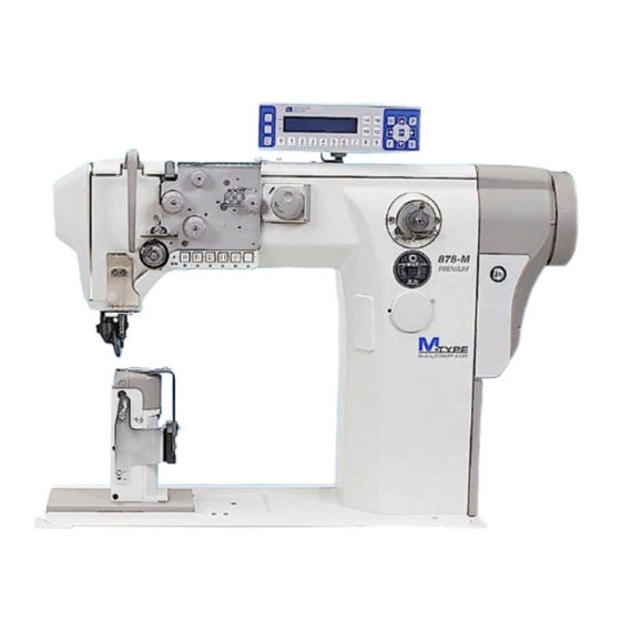
- Page 1 878-M Service Instructions PREMIUM...
- Page 2 IMPORTANT READ THESE INSTRUCTIONS CAREFULLY BEFORE USE AND KEEP THEM FOR FUTURE REFERENCE All rights reserved. Property of Dürkopp Adler AG, protected by copyright. Any reuse of these contents, including extracts, is prohibited without the prior written approval of Dürkopp Adler AG. Copyright ©...
-
Page 3: Table Of Contents
Setting the loop former ............. 40 Setting the opening of the middle part of the hook..... 41 11.1 Setting the lifting gap ..............42 11.2 Setting the timing for lifting ............43 Service Instructions 878-M PREMIUM - 03.0 - 10/2019... - Page 4 17.5.3 Setting the Speed (Speed) parameter........74 17.5.4 Setting the Stop positions (StopPositions) parameter ..74 17.5.5 Setting the Sewing foot (Foot) parameter ....... 75 17.5.6 Setting the Needle thread tension (ThreadTension) parameter ..........75 Service Instructions 878-M PREMIUM - 03.0 - 10/2019...
- Page 5 18.2 Lubricating ................108 18.2.1 Lubricating the machine head..........109 18.2.2 Setting the hook lubrication ............ 110 18.3 Parts List................. 111 Decommissioning..............113 Disposal................. 115 Troubleshooting ..............117 21.1 Customer service..............117 Service Instructions 878-M PREMIUM - 03.0 - 10/2019...
- Page 6 Table of Contents 21.2 Errors in the sewing process ..........118 21.3 Error in the software ............... 120 21.4 Testing the function of the buttons.......... 120 Technical data............... 123 Appendix ................125 Service Instructions 878-M PREMIUM - 03.0 - 10/2019...
-
Page 7: About These Instructions
Steps to be performed when operating the machine (sewing and equipping) Steps to be performed for service, maintenance, and installation Steps to be performed via the software control panel Service Instructions 878-M PREMIUM - 03.0 - 10/2019... - Page 8 Safety ( p. 9). If no other clear location information is used in a figure, indications of right Location information or left are always from the user's point of view. Service Instructions 878-M PREMIUM - 03.0 - 10/2019...
-
Page 9: Other Documents
Leave machines, equipment and packaging material in the condition in which they were found when the damage was discovered. This will ensure any claims against the transport company. Report all other complaints to Dürkopp Adler after receiving the product. Service Instructions 878-M PREMIUM - 03.0 - 10/2019... - Page 10 About these instructions Service Instructions 878-M PREMIUM - 03.0 - 10/2019...
-
Page 11: Safety
• Set up the machine • Perform maintenance work and repairs • Perform work on electrical equipment Only authorized persons may work on the machine and must first under- stand these instructions. Service Instructions 878-M PREMIUM - 03.0 - 10/2019... -
Page 12: Signal Words And Symbols Used In Warnings
If ignored, environmental damage can result. NOTICE (without hazard symbol) If ignored, property damage can result. The following symbols indicate the type of danger to personnel: Symbols Symbol Type of danger General Electric shock Service Instructions 878-M PREMIUM - 03.0 - 10/2019... - Page 13 Consequences of non-compliance. Measures for avoiding the hazard. This is what a warning looks like for a hazard that could result in moderate or minor injury if the warning is ignored. Service Instructions 878-M PREMIUM - 03.0 - 10/2019...
- Page 14 Type and source of danger! Consequences of non-compliance. Measures for avoiding the hazard. This is what a warning looks like for a hazard that could result in property damage if ignored. Service Instructions 878-M PREMIUM - 03.0 - 10/2019...
-
Page 15: Working Basis
3. Cut off any overlapping cable ties. NOTICE Property damage may occur! Excess cables can impair the functioning of moving machine parts. This impairs the sewing function and can result in damage. Lay excess cable as described above. Service Instructions 878-M PREMIUM - 03.0 - 10/2019... -
Page 16: Machine Operation Lock
3. Press the button (1). The button goes out. The power supply is on again. WARNING Risk of injury! Before performing service, switch off the machine by using the main switch. Service Instructions 878-M PREMIUM - 03.0 - 10/2019... -
Page 17: Removing The Covers
Access to the underside of the machine Cover In order to access the components on the underside of the machine, you must first swivel up the machine head. Fig. 2: Access to the underside of the machine Service Instructions 878-M PREMIUM - 03.0 - 10/2019... -
Page 18: Removing And Placing The Arm Covers
(2) - Screws Removing the arm cover 1. Loosen the screws (2). 2. Remove the arm cover (1). Placing the arm cover 1. Place the arm cover (1). 2. Tighten the screws (2). Service Instructions 878-M PREMIUM - 03.0 - 10/2019... -
Page 19: Removing And Placing The Head Cover
Fig. 5: Removing and placing the valve cover ① ② (1) - Valve cover (2) - Screws Important When removing and positioning the valve cover, be sure not to pull off any cables. Service Instructions 878-M PREMIUM - 03.0 - 10/2019... -
Page 20: Disassembling And Assembling The Throat Plate
4. Adjust the throat plate slide (1) at the center of the throat plate (4). 5. Tighten the screws (2). Assembling the throat plate 1. Insert the throat plate (4). 2. Tighten the 2 screws (3). Service Instructions 878-M PREMIUM - 03.0 - 10/2019... -
Page 21: Disassembling And Assembling The Circular Feed Dog
1. Disassemble the throat plate ( p. 18). 2. Remove the plug from the opening (3). 3. Move the feed-dog carrier (2) and the circular feed dog (1) up. 4. Replace the feed dog (1). Service Instructions 878-M PREMIUM - 03.0 - 10/2019... -
Page 22: Flats On Shafts
This stabilizes the connection and makes setting easier. The first screw in the direction of rotation is always screwed on to a flat surface. Important Always ensure that the screws are completely flush with the surface. Service Instructions 878-M PREMIUM - 03.0 - 10/2019... -
Page 23: Locking The Machine In Place
• Setting the handwheel position and checking the top dead center for the needle bar Fig. 10: Locking the machine in place (2) ④ (4) - Locking opening Locking the machine in place 1. Remove the plug from the locking opening (4). Service Instructions 878-M PREMIUM - 03.0 - 10/2019... -
Page 24: Setting The Handwheel Into Position
For some settings, the graduated scale on the handwheel has to be moved to a certain position. 1. Turn the handwheel until the specified number on the graduated scale (1) is next to the marking point (2). Service Instructions 878-M PREMIUM - 03.0 - 10/2019... -
Page 25: Setting The Handwheel Scale
The marking (2) on the handwheel washer (3) marks the position (1). 4. Tighten the 2 threaded pins of the handwheel washer (3). 5. Fit the handwheel (4) and tighten the 3 screws. Service Instructions 878-M PREMIUM - 03.0 - 10/2019... -
Page 26: Positioning The Arm Shaft
4. Push the arm shaft to be flush with the arm shaft crank (3) as far as it will go to the right of the machine casting. 5. Tighten the threaded pins (1) on the arm shaft crank (3). Service Instructions 878-M PREMIUM - 03.0 - 10/2019... -
Page 27: Positioning The Toothed Belt Wheels
(5) - Toothed belt (3) - Winder wheel Proper setting The two threaded pins (4) for the upper toothed belt wheel (1) are set flush on the surface of the arm shaft (2). Service Instructions 878-M PREMIUM - 03.0 - 10/2019... -
Page 28: Positioning The Lower Toothed Belt Wheel
4. Move the lower toothed belt wheel (3) sufficiently far to the side so that the toothed belt (1) makes contact with the retaining ring (2) without being pushed away. 5. Tighten the threaded pins (4). Service Instructions 878-M PREMIUM - 03.0 - 10/2019... -
Page 29: Setting The Needle Bar
Fig. 16: Aligning the needle bar linkage sideways (1) ① (1) - Threaded pins 1. Remove the arm cover ( p. 16). 2. Remove the push buttons. 3. Loosen the two threaded pins (1). Service Instructions 878-M PREMIUM - 03.0 - 10/2019... - Page 30 8. Drive both threaded pins (3) on the arm shaft crank (2). Order Then, check the following settings: • Distance between the hook and the needle ( p. 38) • Loop stroke position ( p. 39) Service Instructions 878-M PREMIUM - 03.0 - 10/2019...
-
Page 31: Angular Position Of The Single-Needle Sewing Machine Needle Holder
5. Insert the 2.5 mm Allen wrench into the opening (4) and loosen the fixing screw of the needle holder inside the needle bar. 6. Turn the needle holder (3) to have the correct setting. 7. Tighten the fixing screw. Service Instructions 878-M PREMIUM - 03.0 - 10/2019... -
Page 32: Setting The Sewing Foot
(1) - Screw (5) - Side position of the sewing foot (2) - Screw (6) - Cross-point screwdriver (3) - Screw (7) - Roller foot holder (4) - Screw (8) - Needle bar Service Instructions 878-M PREMIUM - 03.0 - 10/2019... - Page 33 2. Move the sewing foot (4) manually up onto the feed dog. 3. Using the screw (1) set the gap (A) = ~1 mm between the gripping connection of the foot bar (3) and the sleeve (2). Service Instructions 878-M PREMIUM - 03.0 - 10/2019...
- Page 34 The gap value is set by the respective parameter. No sewing material is allowed under the sewing foot when the machine is switched on! Service Instructions 878-M PREMIUM - 03.0 - 10/2019...
-
Page 35: Needle Guides In 2-Needle Machines
(3) in the sewing direction using the screw (6), using the holder (2) for side adjustment. Adjust the front guide in the sewing direction and on the sides using the screw (7). 4. Firmly tighten all fixing screws. Service Instructions 878-M PREMIUM - 03.0 - 10/2019... -
Page 36: Setting The Hook And The Needle Bar
(1) - Screw (3) - Screws (2) - Ring 1. Loosen the screw (1). 2. Loosen the screws (3). 3. Move the hook vertically to the distance (A). 4. Tighten the screws (3). Service Instructions 878-M PREMIUM - 03.0 - 10/2019... -
Page 37: Setting The Looping Stroke
• A straight and undamaged needle has been inserted ( Operating Instructions) Proper setting The machine is locked in position 1 ( p. 21). The hook tip (2) points exactly to the needle axis (1). Service Instructions 878-M PREMIUM - 03.0 - 10/2019... - Page 38 4. Tighten the threaded pins (2) of the clamping ring (1). 5. Remove the lock. Order Then, check the following settings: • Position of the needle guard ( p. 39) • Setting the cutoff curve ( p. 55) Service Instructions 878-M PREMIUM - 03.0 - 10/2019...
-
Page 39: Setting The Needle Bar Height
Do not turn the needle to the side. The needle groove (4) must face the hook. 4. Tighten the screw (1) of the needle bar (2). Order Then, check the following settings: • Position of the needle guard ( p. 39) Service Instructions 878-M PREMIUM - 03.0 - 10/2019... -
Page 40: Setting The Side Distance Of The Hook
7. Tighten the screws (6) slightly, and using the feed screw (7) move the hook column. The distance between the hook tip (4) and the needle groove (3) is 0.02 to 0.1 mm. The hook tip (4) shall not touch the needle. Service Instructions 878-M PREMIUM - 03.0 - 10/2019... -
Page 41: Setting The Needle Guard
(4) - Needle (2) - 3 mm Allen wrench (5) - Hook tip (3) - Needle guard 3. Turn the handwheel to check how far the needle guard (3) has pushed the needle. Service Instructions 878-M PREMIUM - 03.0 - 10/2019... -
Page 42: Setting The Loop Former
1. Set the maximum stitch length based on the sewing equipment used. 2. Disassemble the throat plate ( p. 18). Fig. 28: Setting the loop former ① (1) - Loop former 3. Bend the loop former as specified in the correct setting. Service Instructions 878-M PREMIUM - 03.0 - 10/2019... -
Page 43: Setting The Opening Of The Middle Part Of The Hook
Error Errors at the incorrect setting of the opening of the middle part of the hook: • Thread breaking • Forming loops at the bottom side of the stitch • Noisy machine Service Instructions 878-M PREMIUM - 03.0 - 10/2019... -
Page 44: Setting The Lifting Gap
Make sure that the gap is not too large. The middle part of the hook must not collide with the edges of the throat plate groove (2). 7. Tighten the threaded pin (3). 8. Plug the opening again. Service Instructions 878-M PREMIUM - 03.0 - 10/2019... -
Page 45: Setting The Timing For Lifting
4. Loosen the threaded pin (3). 5. Set the angle of the handwheel as specified in the correct setting. 6. Tighten the threaded pin (3). 7. Plug the opening again. 8. Perform a test sewing. Service Instructions 878-M PREMIUM - 03.0 - 10/2019... -
Page 46: Setting The Needle Thread Tension
Fig. 33: Setting the needle thread regulator ① ② (1) - Screw (2) - Needle thread regulator 2. Turn the handwheel and observe the cycle of the needle thread around the hook. 3. Loosen the screw (1). Service Instructions 878-M PREMIUM - 03.0 - 10/2019... -
Page 47: Setting The Thread Tensioning Spring
3. Turn the tension disk (3) to set the spring tension. • Greater spring tension: turn counterclockwise • Lower spring tension: turn clockwise Important Be careful not to twist the stop collar. 4. Tighten the screw (4). Service Instructions 878-M PREMIUM - 03.0 - 10/2019... -
Page 48: Setting The Thread Lever Mechanism
The needle thread tension is controlled by the set value of the respective parameter. If you have any inquiries about the electronic needle thread tension, please consult Customer Service ( p. 117). Service Instructions 878-M PREMIUM - 03.0 - 10/2019... -
Page 49: Winder
1. Loosen the threaded pins (1). 2. Move the toothed belt wheel (2) to the right or left so that the distance from the winder wheel (3) is exactly 0.8 mm. 3. Tighten the threaded pins (1). Service Instructions 878-M PREMIUM - 03.0 - 10/2019... -
Page 50: Setting The Winder
• Arms (4) further apart from each other: turn clockwise 5. Put the completely filled bobbin onto the winder. 6. Fold the winder lever (3) upwards as far as it will go to the thread. Service Instructions 878-M PREMIUM - 03.0 - 10/2019... - Page 51 10. Set the block (8) such that it is resting against the locking disk (9). 11. Set the block (8) such that its distance to the winder wheel (10) is 0.5 mm. 12. Tighten the threaded pin in the block (8). Service Instructions 878-M PREMIUM - 03.0 - 10/2019...
- Page 52 16. Tighten the threaded pin (13). Installing the winder Fig. 41: Setting the winder (5) ① (1) - Screws 17. Place the winder on the machine arm. 18. Tighten the screws (1). Service Instructions 878-M PREMIUM - 03.0 - 10/2019...
-
Page 53: Setting The Hook Thread Guide
2. Turn the hook thread guide (2): • To the front: The hook thread will be wound up further to the front. • To the rear: The hook thread will be wound up further to the rear. Service Instructions 878-M PREMIUM - 03.0 - 10/2019... -
Page 54: Thread Trim
2. Tighten slightly the screw (4) which fits the surface of the thread trim shaft. 3. Tighten the feed screw (3) until the instruction 1 is complied with. 4. Tighten the screw (4) and then the screw (5) as well. Service Instructions 878-M PREMIUM - 03.0 - 10/2019... - Page 55 10. Tighten the screws (7) and (6) and check whether the knives are touching at the distance (C). Important If the cutting pressure of the fixed knife is set too high, this will result in its excessive wear. Service Instructions 878-M PREMIUM - 03.0 - 10/2019...
-
Page 56: Starting Position Of The Moving Knife
2. Check whether the cutoff curve (3) is pushed as far to the right (2). 3. Turn the cutoff curve (3) as prescribed. 4. Loosen the screw (6). 5. Turn the fixed knife (4) as prescribed. 6. Tighten the screw (6). Service Instructions 878-M PREMIUM - 03.0 - 10/2019... -
Page 57: Setting The Short Thread Trimming
11. Push the moving knife (7) and the lever (13) to the end position on the throat plate as instruction 3. 12. Tighten the clamp joint screw (12) on the roller (10) lever. Service Instructions 878-M PREMIUM - 03.0 - 10/2019... -
Page 58: Setting The Cutoff Curve
9. Check the setting of the distance as prescribed in instruction 1, the angle of the cutoff curve according to instruction 2 and that of the looping stroke ( p. 35). Service Instructions 878-M PREMIUM - 03.0 - 10/2019... -
Page 59: Hook Thread Clamp
3. Set and adjust the pressure of the hook thread clamp (1) using the screw (3) until the instruction is complied with. Error If the hook thread clamp is set incorrectly, difficulties may appear during sewing. Service Instructions 878-M PREMIUM - 03.0 - 10/2019... -
Page 60: Setting The Safety Snap-On Coupling
1. Tilt the machine head ( p. 15). 2. Turn the left adjusting ring (2) such that the threaded pins (1) are parallel to one another. The safety snap-on coupling latches into place. Service Instructions 878-M PREMIUM - 03.0 - 10/2019... -
Page 61: Setting The Torque
(6) so that 8 Nm is reached for the torque: • Increase force: turn in the direction + • Decrease force: turn in the direction – 4. Tighten the screw (7). Service Instructions 878-M PREMIUM - 03.0 - 10/2019... -
Page 62: Integrated Motor
(3) - Threaded pins (2) - Screws (4) - Washer 1. Loosen all three screws (2) on the handwheel (1). 2. Loosen all threaded pins (3) and remove the handwheel flange (4). Service Instructions 878-M PREMIUM - 03.0 - 10/2019... -
Page 63: Removing The Cover
3. Loosen the screws (1) and disconnect the cables from the motor. 4. Loosen the 3 screws (2) on the motor flange. 5. Remove the motor from the machine as indicated by the arrow. Service Instructions 878-M PREMIUM - 03.0 - 10/2019... -
Page 64: Assembling The Cover
16.1.4 Assembling the cover Fig. 53: Assembling the cover ① ② ① (1) - Screws (2) - Cover 1. Place the cover (2). 2. Tighten the screws (1). Service Instructions 878-M PREMIUM - 03.0 - 10/2019... -
Page 65: Assembling The Handwheel
Integrated motor 16.1.5 Assembling the handwheel Fig. 54: Assembling the handwheel ① ② (1) - Handwheel (2) - Screws 1. Fit the handwheel (1) and tighten all three screws (2). Service Instructions 878-M PREMIUM - 03.0 - 10/2019... - Page 66 Integrated motor Service Instructions 878-M PREMIUM - 03.0 - 10/2019...
-
Page 67: Programming
For a description of how to create programs or how to make changes to the sewing parameters, the programming on the Operator level is explained in the Operating Instructions 878-M PREMIUM. 17.1 Calling up the Technician level A password is requested to make it possible to make changes on the Technician level. -
Page 68: Parameter Selection (Parametercall) Submenu
Cat category and select the desired ► value with the ▲/▼ buttons or the number keys. The categories are explained in the Parameter list 878-M PREMIUM. 5. Use the button to move to the Par parameter and select the desired- ► ▲/▼... -
Page 69: Program Presetting (Defaultprogram) Submenu
2. Press the OK button to confirm the selection. 3. Enter the desired value (00.0 – 7.0 mm) based on the maximum stitch length T3010 4. Press the OK button to confirm the value. Service Instructions 878-M PREMIUM - 03.0 - 10/2019... -
Page 70: Setting The Foot Pressure (Footpress.) Parameter
1. Select the FullnessType parameter. 2. Press the OK button to confirm the selection. 3. Select the upper or lower fullness degrees. 4. Press the OK button to confirm the value. Service Instructions 878-M PREMIUM - 03.0 - 10/2019... -
Page 71: Setting The Fullness Degrees (Fullness) Parameter
Menu item Setting option The thread trim is activated automatically at the end of a seam section and at the end of the sewing program. The thread trim is not activated. Service Instructions 878-M PREMIUM - 03.0 - 10/2019... -
Page 72: Setting The Daily Piece Counter (Dailypieces) Parameter
Material thickness detection FabricThickness p. 80 Correcting effects of high speed Speed Corr p. 81 Light barrier LightBarrier p. 81 Segment length Mode Seg.Size p. 82 Threading mode Threading Service Instructions 878-M PREMIUM - 03.0 - 10/2019... -
Page 73: Setting The Thread Trim (Threadtrim) Parameter
(visually) as small as possible. (Value range 00 – 99) St.Length Stitch length of the short stitches, generally between 01.0 – 01.5 [mm]. (Value range -7.0 – 7.0) Service Instructions 878-M PREMIUM - 03.0 - 10/2019... -
Page 74: Setting The Thread Clamp (Threadclamp) Parameter
The thread clamp can be activated or deactivated. On/Off Various modes (1 to 10) are available; explanations can be found Mode in the Parameter data sheet 878-M PREMIUM. On/Off Thickness Lifting height of the sewing foot depending on the thickness of the material. - Page 75 Exhaust removal of the trimmed residual thread. On° – Position for the start of exhaust removal (Value range 000 – 359) Off[ms] – Duration of the exhaust removal (Value range 00000 – 99999 [ms]) Service Instructions 878-M PREMIUM - 03.0 - 10/2019...
-
Page 76: Setting The Speed (Speed) Parameter
Value range (000 – 359) Holding position of the needle outside of the material. StopTop° Value range (000 – 359) Stop position after thread trimming (reversal position). StopIdle° Value range (000 – 359) Service Instructions 878-M PREMIUM - 03.0 - 10/2019... -
Page 77: Setting The Sewing Foot (Foot) Parameter
[s] Activation duration of the thread trim in time period t2. (Value range 000 – 600 [s]) DtyC. t2 [%] Duty cycle in time period t2 (Value range 000 – 100 [%]) Service Instructions 878-M PREMIUM - 03.0 - 10/2019... -
Page 78: Setting The Stitch Length (Stitchlength) Parameter
The speed is limited during sewing by the set stitch length value. Limitatio (Value range 1.0 – 7.0 [mm]) Speed Value for limiting the speed from a defined, adjustable stitch length. (Value range 0050 – 2500 [rpm]) Service Instructions 878-M PREMIUM - 03.0 - 10/2019... -
Page 79: Setting The Bobbin (Bobbin) Parameter
Position control; the position is checked and resets itself. Holding current of the motor Max.Current (Value range 00 – 50) Response time for the continuous current Response (Value range 000 – 100) Service Instructions 878-M PREMIUM - 03.0 - 10/2019... -
Page 80: Setting The Pedal (Pedal) Parameter
(Value range 0000 – 6000 [rpm]) Needle cooling is activated when the edge cutter is also activated. EdgeTrimmer t Delay Lag time, after which the needle cooling is deactivated. (Value range 00.0 – 10.0 [ms]) Service Instructions 878-M PREMIUM - 03.0 - 10/2019... -
Page 81: Setting The Seam Center Guide (Centerguide) Parameter
This will vary depending on the sewing equipment and MUST be adjusted when changing the sewing equipment. ATTENTION The entered value is the gap measured between the NEEDLE and the edge guide. (Value range 01.0 – 20.0 [mm]) Service Instructions 878-M PREMIUM - 03.0 - 10/2019... -
Page 82: Setting The Material Thickness Detection (Fabricthickness) Parameter
This tolerance is designed to ensure that there is no constant alternating between activation and deactivation in the boundary range. (Value range 0 – 2000 [rpm]) Service Instructions 878-M PREMIUM - 03.0 - 10/2019... -
Page 83: Setting The Light Barrier (Lightbarrier) Parameter
Menu item Setting options Seam sections are measured via the length specification (in mm). By Size Seam sections are measured via the stitch count. By Count Service Instructions 878-M PREMIUM - 03.0 - 10/2019... -
Page 84: Setting The Threading Mode (Threading) Parameter
p. 88 Access rights Lock Activity recording QONDAC p. 89 Can be switched between standard and FastMenuKeys simplified display menu. p. 89 Contrast Contrast p. 89 Brightness Brightness Service Instructions 878-M PREMIUM - 03.0 - 10/2019... -
Page 85: Setting The Language Selection (Language) Parameter
° T0210 Stop Trim° T0211 When ParameterView is active, the item ParameterCall is added to the menus in both manual mode and automatic mode. This function is described separately ( p. 66). Service Instructions 878-M PREMIUM - 03.0 - 10/2019... -
Page 86: Setting The Input Configuration (Inputconfig) Parameter
Operation lock input X120B.2 (input on the circuit board) DB3000 IN (X23) X120B.15 (input on the circuit board) Light barrier (X21) (optional) X100B.4 Additional button S1 (optional) X120B.16 Additional button S2 (optional) X120B.4 Service Instructions 878-M PREMIUM - 03.0 - 10/2019... -
Page 87: Setting The Output Configuration (Outputconfig) Parameter
The pins on the circuit board are labeled and must be allo- cated according to the table, depending on what was connected to the pin. Machine output signal Output ML (X22) X120B.9 NK (X22) X120B.10 RA (X16) X120B.12 Service Instructions 878-M PREMIUM - 03.0 - 10/2019... -
Page 88: Setting The Stitch Functions (Stitchfunctions) Parameter
If the operator sews half stitches or full stitches manually, they can also be counted, if required. To do so, this function must be active. The electronic handwheel is not affected by this setting. Service Instructions 878-M PREMIUM - 03.0 - 10/2019... -
Page 89: Setting The Programs (Programs) Parameter
(Value range On/Off) Pedal Abort Abort a program by pressing the pedal in Position -2 twice. (Value range On/Off) 17.6.7 Setting the Electronic handwheel (JogDial) parameter The electronic handwheel can be activated or deactivated. Service Instructions 878-M PREMIUM - 03.0 - 10/2019... -
Page 90: Setting The Access Rights (Lock) Parameter
Restriction of access to the correction factor St.Len.Corr for the stitch length (Value range R/W, Off, R/O) Restriction of access to the correction factor Tens.Corr for the needle thread tension (Value range R/W, Off, R/O) Service Instructions 878-M PREMIUM - 03.0 - 10/2019... -
Page 91: Setting The Fast Menu Keys (Fastmenukeys) Parameter
To set the parameter: 1. Select the Brightness parameter. 2. Press the OK button to confirm the selection. 3. Enter the desired value (000 – 255). 4. Press the OK button to confirm the value. Service Instructions 878-M PREMIUM - 03.0 - 10/2019... -
Page 92: Service (Service) Submenu
Test of the outputs according to the interconnection diagram. To test the outputs: 1. Select the desired output with the / buttons. Fig. 59: Test Output subitem Value Output ON(1) 2. Press the OK button to activate/deactivate the selected output. Service Instructions 878-M PREMIUM - 03.0 - 10/2019... - Page 93 Value ON(1) 2. Confirm the selected element (e.g. button, knee lever, etc.). 3. Observe the display on the control panel. If the element is functional, the display switches between under Value Service Instructions 878-M PREMIUM - 03.0 - 10/2019...
- Page 94 Fig. 63: Test Sew. Motor (Test of the sewing motor) Sewing Motor Speed 3. Press the OK button to confirm the input. The sewing motor runs at the entered speed. 4. To end, press the OK or ESC button. Service Instructions 878-M PREMIUM - 03.0 - 10/2019...
- Page 95 There is no specific procedure for testing the stepper motor encoders. The encoders are tested along with the stepper motors. If the result for the stepper motors is OK, the encoders will be functional as well. Service Instructions 878-M PREMIUM - 03.0 - 10/2019...
-
Page 96: Setting The Service Routine (Adjustments) Parameter
Reference p. 95 Calibration of the stitch adjustment lever (optional Man.St.Len. equipment) Calibration of the edge guide (optional equipment) p. 95 EdgeGuide p. 95 Calibration of the pedal Pedal Service Instructions 878-M PREMIUM - 03.0 - 10/2019... - Page 97 Only one value needs to be checked when calibrating the pedal. To calibrate the pedal: 1. Call up the Service > Calibration > Pedal (Service > Calibration > Pedal) menu item. 2. Follow the instructions on the display. Service Instructions 878-M PREMIUM - 03.0 - 10/2019...
-
Page 98: Setting The Parameter Setting The Gap Between The Foot And The Feed Dog (Footzeroheight)
OK. There is no further query, and there is also no message stating that the reset was performed. To reset the data: 1. Select the Reset parameter. 2. Press the OK button to confirm the selection. Service Instructions 878-M PREMIUM - 03.0 - 10/2019... -
Page 99: Data Transfer (Datatransfer) Submenu
All data – i.e. parameter settings, programs and calibration values – are transfered to the USB key or the control. To transfer all data: 1. Plug the USB key into the socket (1) on the control (2). Service Instructions 878-M PREMIUM - 03.0 - 10/2019... - Page 100 All Data will lost 6. To cancel, press the ESC button; to continue, press the OK button. The data transfer begins and a message appears, stating that the USB key must not be removed. Service Instructions 878-M PREMIUM - 03.0 - 10/2019...
-
Page 101: Setting The Only Data (Onlydata) Parameter
3. Press the OK button to confirm the selection. 4. Use the ▲/▼ buttons to choose between the options Load from USB or Store to USB. 5. Press the OK button. The following warning message appears: Service Instructions 878-M PREMIUM - 03.0 - 10/2019... -
Page 102: Setting The Programs (Programs) Parameter
It is possible to transfer all or just specific programs to the USB key or the control. To transfer the programs: 1. Plug the USB key into the socket (1) on the control (2). Service Instructions 878-M PREMIUM - 03.0 - 10/2019... - Page 103 8. Repeat the selection for all the desired programs or select all programs at the same time (see next step). 9. Press the button; the selection Destination, Select All, ► Deselect All appears. ▲/▼ 10. Select the Select All option with the buttons. Service Instructions 878-M PREMIUM - 03.0 - 10/2019...
-
Page 104: Selection Of Tension Plate Type
2. Use the numeric buttons to enter the code 85627. 3. Select the menu MachineClass. 4. Select the class 878 and the appropriate subclass. 5. Select the tension plate type. Service Instructions 878-M PREMIUM - 03.0 - 10/2019... -
Page 105: Perform Software Update
Fig. 77: Perform software update ③ OP3000 2014-11-27 (3) - Firmware version As soon as the software update is finished, the display will also show the software version (4) of the machine on the right. Service Instructions 878-M PREMIUM - 03.0 - 10/2019... - Page 106 4. Wait until the machine has started and is showing manual mode or automatic mode. 5. Remove the USB key from the control. The software update is complete and the machine is ready to sew. Service Instructions 878-M PREMIUM - 03.0 - 10/2019...
-
Page 107: Maintenance
Maintenance intervals Number of operating Work to be carried out hours Machine head Removing lint and thread remnants Checking the oil level Checking the hook lubrication Service Instructions 878-M PREMIUM - 03.0 - 10/2019... -
Page 108: Cleaning
Lint and thread remnants should be removed after every 8 operating hours using a compressed air gun or a brush. If very fluffy sewing material is being sewn, the machine must be cleaned more frequently. Service Instructions 878-M PREMIUM - 03.0 - 10/2019... - Page 109 • Cutter on the winder for the hook thread (4) • Area under the throat plate (3) • Hook (2) • Area around the needle (1) 1. Remove any lint and thread remnants using a compressed air gun or a brush. Service Instructions 878-M PREMIUM - 03.0 - 10/2019...
-
Page 110: Lubricating
• Flash point: 150 °C You can order the lubricating oil from our sales offices using the following part numbers: Container Part No. 250 ml 9047 000011 9047 000012 9047 000013 9047 000014 Service Instructions 878-M PREMIUM - 03.0 - 10/2019... -
Page 111: Lubricating The Machine Head
The oil level must not rise above the MAX marking point (2) or drop below the MIN marking point (3). 1. Fill the oil through the oil filler opening (1) up to the MAX marking point (2). Service Instructions 878-M PREMIUM - 03.0 - 10/2019... -
Page 112: Setting The Hook Lubrication
• Releasing less oil: turn clockwise Important The released amount of oil does not change until the operating time has run a few minutes. Sew for several minutes before you check the setting again. Service Instructions 878-M PREMIUM - 03.0 - 10/2019... -
Page 113: Parts List
Maintenance 18.3 Parts List A parts list can be ordered from Dürkopp Adler. For more information, visit our website: www.duerkopp-adler.com Service Instructions 878-M PREMIUM - 03.0 - 10/2019... - Page 114 Maintenance Service Instructions 878-M PREMIUM - 03.0 - 10/2019...
-
Page 115: Decommissioning
5. Cover the control panel to protect it from soiling. 6. Cover the control cabinet to protect it from soiling. 7. Cover the entire machine if possible to protect it from contamination and damage. Service Instructions 878-M PREMIUM - 03.0 - 10/2019... - Page 116 Decommissioning Service Instructions 878-M PREMIUM - 03.0 - 10/2019...
-
Page 117: Disposal
When disposing of the machine, be aware that it consists of a range of different materials (steel, plastic, electronic components, etc.). Follow the national regulations when disposing these materials. Service Instructions 878-M PREMIUM - 03.0 - 10/2019... - Page 118 Disposal Service Instructions 878-M PREMIUM - 03.0 - 10/2019...
-
Page 119: Troubleshooting
Contact address for repairs and issues with the machine: Dürkopp Adler AG Potsdamer Str. 190 33719 Bielefeld Tel.: +49 (0) 180 5 383 756 Fax: +49 (0) 521 925 2594 Email: service@duerkopp-adler.com Internet: www.duerkopp-adler.com Service Instructions 878-M PREMIUM - 03.0 - 10/2019... -
Page 120: Errors In The Sewing Process
Check the assembly of the reel incorrectly stand Thread tensions are too Check the thread tensions tight Throat plate, hook or Have parts reworked by qualified spread have been specialists damaged by the needle Service Instructions 878-M PREMIUM - 03.0 - 10/2019... - Page 121 Needle thread and hook Check the threading path thread have not been threaded correctly Needle breakage Needle strength is Use the recommended needle unsuitable for the sewing strength material or the thread Service Instructions 878-M PREMIUM - 03.0 - 10/2019...
-
Page 122: Error In The Software
1. Switch off the machine with the main switch. 2. Hold the ESC button pressed down, and at the same time switch on the machine with the main switch. The display shows the this window: Service Instructions 878-M PREMIUM - 03.0 - 10/2019... - Page 123 If all the buttons are functional, the display shows the following status message: 5. Press the OK button. If one or several buttons are not functional: The display shows the status message Keys NOT OK! The control panel has to be replaced. Service Instructions 878-M PREMIUM - 03.0 - 10/2019...
- Page 124 Troubleshooting Related instructions: Electronic handwheel 0791 867951 Hook thread monitoring Instructions for safety elements Parameter data sheet DAC Comfort 0791 867980 EN Basic information about the M-Type Premium 0791 867304 DE Service Instructions 878-M PREMIUM - 03.0 - 10/2019...
-
Page 125: Technical Data
Sewing foot stroke [mm] Lifting height [mm] Mains voltage Mains frequency [Hz] 50/60 Length [mm] Width [mm] Height [mm] Weight [kg] The Dürkopp Adler 878-M PREMIUM is a double-lockstitch post bed sew- ing machine. Service Instructions 878-M PREMIUM - 03.0 - 10/2019... - Page 126 Technical data Service Instructions 878-M PREMIUM - 03.0 - 10/2019...
-
Page 127: Appendix
Appendix 23 Appendix Wiring diagram Service Instructions 878-M PREMIUM - 03.0 - 10/2019... - Page 128 Appendix Service Instructions 878-M PREMIUM - 03.0 - 10/2019...
- Page 130 DÜRKOPP ADLER AG Potsdamer Straße 190 33719 Bielefeld GERMANY Phone +49 (0) 521 / 925-00 service@duerkopp-adler.com E-mail www.duerkopp-adler.com...