Furuno NAVnet TZtouch2 Operator's Manual
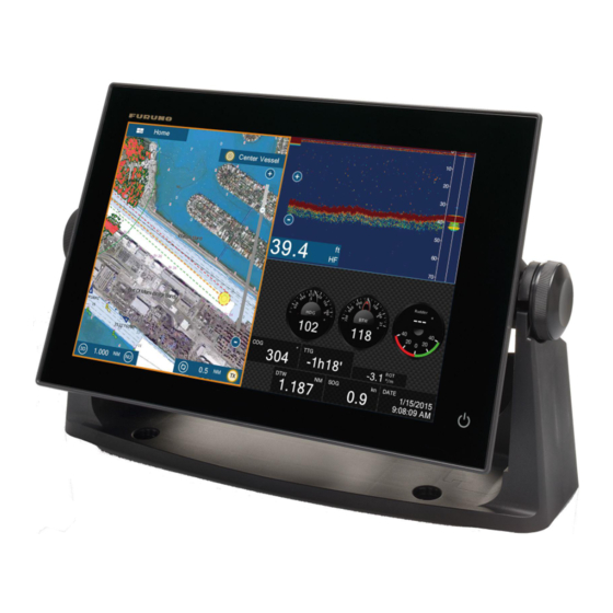
Multi function display
Hide thumbs
Also See for NAVnet TZtouch2:
- Setup procedures (19 pages) ,
- Operator's manual (17 pages) ,
- Software update procedure (12 pages)
Table of Contents
Advertisement
Quick Links
9-52 Ashihara-cho,
Nishinomiya, 662-8580, JAPAN
All rights reserved.
Printed in Japan
Pub. No. OME-44870-H
(GREG) TZTL12F/TZTL15F/TZT2BB
(Elemental Chlorine Free)
The paper used in this manual
is elemental chlorine free.
FURUNO Authorized Distributor/Dealer
A : MAY. 2015
H : JUL.27 2020
00019006917
MULTI FUNCTION DISPLAY
MULTI FUNCTION DISPLAY
TZTL12F/TZTL15F/TZT2BB
Model
www.furuno.com
Advertisement
Table of Contents

Related Manuals for Furuno NAVnet TZtouch2


Summary of Contents for Furuno NAVnet TZtouch2
- Page 1 MULTI FUNCTION DISPLAY TZTL12F/TZTL15F/TZT2BB Model (Elemental Chlorine Free) The paper used in this manual is elemental chlorine free. FURUNO Authorized Distributor/Dealer 9-52 Ashihara-cho, Nishinomiya, 662-8580, JAPAN A : MAY. 2015 All rights reserved. Printed in Japan H : JUL.27 2020 Pub.
- Page 2 How to discard a used battery Some FURUNO products have a battery(ies). To see if your product has a battery, see the chapter on Maintenance. Follow the instructions below if a battery is used. Tape the + and - terminals of bat- tery before disposal to prevent fire, heat generation caused by short circuit.
- Page 3 SAFETY INSTRUCTIONS Read these safety instructions before you operate the equipment. WARNING Indicates a condition that can cause death or serious injury if not avoided. CAUTION Indicates a condition that can cause minor or moderate injury if not avoided. Warning, Caution Prohibitive Action Mandatory Action WARNING...
- Page 4 SAFETY INSTRUCTIONS CAUTION WARNING The fish finder picture is not Keep units other than the radar refreshed when the picture antenna away from rain and advance setting is “OFF”. water. Do not use high-pressure cleaners Fire or electrical shock can occur if to clean this equipment.
- Page 5 Safety Labels malfunction. A safety label is attached to the display unit. Do not remove the label. If the label is missing or damaged, contact a FURUNO agent or dealer about replacement. Name: Warning Label (1) WARNING Type: 86-003-1011-3 To avoid electrical shock, do not remove cover.
-
Page 6: Table Of Contents
TABLE OF CONTENTS FOREWORD ......................... xiv SYSTEM CONFIGURATION ..................xvi SYSTEM INTRODUCTION ..................1-1 1.1 Controls ........................1-2 1.2 Remote Control Units (option) ..................1-5 1.2.1 Remote Control MCU-002................1-5 1.2.2 Remote Control Unit MCU-004 ..............1-6 1.2.3 Control Unit MCU-005 ..................1-7 1.2.4 Remote Control Unit group settings ...............1-9 1.3 How to Turn the Power On or Off ................1-11 1.4 How to Adjust the Brilliance of the Display and Power Switch and Hue....1-13 1.5 Home Screen......................1-14... - Page 7 TABLE OF CONTENTS 2.5.3 COG vector length ..................2-5 2.5.4 Boat icon orientation ..................2-6 2.6 How to Information About a Chart Object, Chart............2-6 2.6.1 Chart object information ................. 2-6 2.6.2 Chart information.................... 2-7 2.7 How to Find the Range and Bearing Between Two Locations........2-8 2.8 Multiple Plotter Displays.....................
- Page 8 TABLE OF CONTENTS 4.4 Event Mark Comment....................4-5 4.5 Default Point, Event Mark Settings................4-5 4.5.1 Default point settings..................4-5 4.5.2 Default event mark settings ................4-7 4.6 How to Find Number of Points Used ................4-7 4.7 Points List ........................4-8 4.7.1 How to show the points list................4-8 4.7.2 How to sort the points list ................4-8 4.7.3...
- Page 9 TABLE OF CONTENTS 5.4 Routes List ......................... 5-6 5.5 How to Find Number of Routes Created ..............5-8 5.6 How to Find a Route on the Chart................5-8 5.7 How to Delete a Route ....................5-8 5.7.1 How to delete a route on the screen .............. 5-8 5.7.2 How to delete a route from the routes list ............
- Page 10 TABLE OF CONTENTS 6.14.1 How to set the guard zone ................6-15 6.14.2 How to activate or deactivate the guard zone ..........6-16 6.14.3 How to hide the guard zone .................6-16 6.15 Watchman ........................6-16 6.16 Echo Trail .........................6-17 6.16.1 How to show, hide echo trails...............6-17 6.16.2 How to clear echo trails ................6-17 6.16.3 How to select echo trail length ..............6-17 6.16.4 How to select the echo trail mode (reference)..........6-18...
- Page 11 TABLE OF CONTENTS 7.6 Picture Advance Speed....................7-9 7.7 How to Reduce Interference ..................7-10 7.8 How to Measure Range, Depth to an Object ............7-10 7.9 Echo History Display ....................7-11 7.10 How to Balance Echo Strength ................7-11 7.11 Fish Finder Alarms ....................
- Page 12 TABLE OF CONTENTS 8.6.6 How to calibrate the seabed echo ..............8-13 8.6.7 How to use the noise filter ................8-14 8.6.8 How to use terrain shading................8-14 8.6.9 How to change the picture advance speed ..........8-14 8.6.10 Depth/Color Shading display ................8-15 8.6.11 How to show or hide the scale box...............8-19 8.6.12 Availability of points and event marks registration, and go to a point...8-19 FILE OPERATIONS ....................9-1 9.1 File Format .........................9-1...
- Page 13 TABLE OF CONTENTS 12.3.5 Troll mode ....................12-29 12.3.6 Trouble codes .................... 12-30 12.3.7 Alarm list ....................12-30 13. WEATHER OPERATIONS...................13-1 13.1 Weather Display Introduction ................... 13-1 13.2 NavCenter Weather ....................13-2 13.2.1 How to set up for NavCenter weather ............13-2 13.2.2 How to download the NavCenter weather data..........
- Page 14 TABLE OF CONTENTS 16. MAINTENANCE, TROUBLESHOOTING ............16-1 16.1 Maintenance ......................16-1 16.2 Fuse Replacement ....................16-2 16.3 Life of Parts ......................16-2 16.4 Troubleshooting......................16-3 16.4.1 General troubleshooting ................16-3 16.4.2 Radar troubleshooting ..................16-4 16.4.3 Plotter troubleshooting .................16-4 16.4.4 Fish finder troubleshooting ................16-4 APPENDIX 1 MENU TREE ..................AP-1 APPENDIX 2 RADIO REGULATORY INFORMATION ..........AP-13 SPECIFICATIONS .....................
-
Page 15: Foreword
NavNet TZtouch2 units through Ethernet or NMEA 2000. The plug-and- play format allows expansion and you can connect a maximum of six NavNet TZtouch2 units (for configurations with a TZT2BB on the same network as the TZTL12F/15F, the maximum number of TZTL12F/15F units is four.). - Page 16 FOREWORD • Points (waypoints) and routes are transferred and shared between NavNet TZtouch2 units via Ethernet. • Large memory stores 30,000 track points, 30,000 points, and 200 routes (500 points per route), 200 boundaries, 1000 photos and 1000 catches. • Able to write and read data (points, routes, tracks, etc.).
-
Page 17: System Configuration
See the radar sensor Installation Manual (IME-35670) for details. A maximum of 6 NavNet TZtouch2 units can be connected via Ethernet hub. With connection of a TZT2BB unit, the maximum number of units is 4. These units are internally fittted with a GPS antenna/receiver and fish finder as standard. - Page 18 DRS2D/4D/6A/12A: PSU-012; DRS25A/: PSU-013; DRS2D/4D: PSU-017 supply Max. 6 NavNet TZtouch2 units connected via Ethernet hub. For configurations with TZT2BB included, a maximum of 4 NavNet TZtouch2 units can be connected. Hatteland Display monitor. Use an after-market PoE hub. The NETGEAR GS108PE is confirmed as compatible. Compatibility tests are limited to general use as part of this configuration and in no way indicates overall capability.
- Page 19 SYSTEM CONFIGURATION This page is intentionally left blank. xviii...
-
Page 20: System Introduction
SYSTEM INTRODUCTION This chapter provides the information necessary to get you started using your system. Standards used in this manual • Key names are shown in boldface type. For example, ENT key (on the MCU-002, MCU-004 or MCU-005). • Menu items, on-screen indications, and pop-up menus and pop-up windows names are shown in brackets. -
Page 21: Controls
1. SYSTEM INTRODUCTION Controls The TZTL12F and TZTL15F are operated by a power switch on the front panel and a microSD card slot, which is used for chart data, is on the rear panel. The power switch is also used to adjust brilliance. The TZT2BB uses the Switch Box (PSD-003) for power and SD cards. - Page 22 1. SYSTEM INTRODUCTION About the soft cover The soft cover (supplied with TZTL12F/TZTL15F) pro- tects the LCD when the display unit is not in use. To re- move the cover, grasp the cover at the locations circled in the right figure and pull forward. Touchscreen operations The tables which follow outline the touchscreen opera- tions.
- Page 23 1. SYSTEM INTRODUCTION Notes on touch control operations • Waterdrops on the screen can cause mis-operation and slow touch response. Wipe the screen with a dry cloth to remove the water. • This equipment uses a capacitive touch screen. Tap the screen with your fingertips directly.
-
Page 24: Remote Control Units (Option)
- AUTO modeSTBY mode: "NAVpilot is disengaged." 1.2.1 Remote Control MCU-002 Function STBY•AUTO Switches the steering mode of the FURUNO NAVpilot series Autopilot between the STBY and AUTO modes. CENTER key • Returns own ship to the center of the screen (Plotter/Weather/Radar display). -
Page 25: Remote Control Unit Mcu-004
1. SYSTEM INTRODUCTION 1.2.2 Remote Control Unit MCU-004 Function STBY•AUTO Switches the steering mode of the FURUNO NAVpilot series Autopilot between the STBY and AUTO modes. HOME/BRILL • Short press: Opens the home screen. • Long press: Opens the Brilliance/Power win- dow. -
Page 26: Control Unit Mcu-005
1. SYSTEM INTRODUCTION 1.2.3 Control Unit MCU-005 Key Name Description Power lamp When the power is on, the lamp is lit. EVENT key Inscribes an event mark at your current position. GAIN/TX key Short press: • Adjusts the radar gain/AC SEA/AC RAIN or adjust the Fish Finder/Multi-beam Sounder gain. - Page 27 Note: CURSOR key "short press" and "long press" operations are the same as "tap" and "long tap" operations respectively. STBY/AUTO key Switches the steering mode of the connected FURUNO NAVpilot series between the STBY and AUTO modes. POINTS/ROUTE key Short press: •...
-
Page 28: Remote Control Unit Group Settings
1.2.4 Remote Control Unit group settings If multiple NavNet TZtouch2 units are installed in the network, you can the select the display to show on a unit, using the MCU-004 or MCU-005. Additionally, you can se- lect the order in which to cycle through the displays. - Page 29 1. SYSTEM INTRODUCTION Based on the menu settings shown on the previous page, the installed configura- tion should look similar to the following image. (A) TZTL12F_FB_LEFT (B) TZTL12F_FB_RIGHT FLYBRIDGE MCU1 (A) and (B) can be controlled STBY STBY HOME • •...
-
Page 30: How To Turn The Power On Or Off
1. SYSTEM INTRODUCTION How to Turn the Power On or Off The Power switch ( ) on the front panel controls the power. Power switch TZTL12F/TZTL15F TZT2BB When you turn on the power, he equipment beeps twice and the splash screen ap- pears. - Page 31 1. SYSTEM INTRODUCTION How to turn the power off Tap the power switch to show the [Power & Brilliance] window. Closes the window. Tap either of these two. Tap [Power Off This Equipment] or [Power Off Network], then tap [OK]. 15 seconds after the screen goes blank, the power turns off.
-
Page 32: How To Adjust The Brilliance Of The Display And Power Switch And Hue
1. SYSTEM INTRODUCTION How to Adjust the Brilliance of the Display and Power Switch and Hue With the power applied, press to show the [Power & Brilliance] window. DRS6A_X-CLASS BBDS1 Hue options TZTL12F/15F: Adjust the display brilliance. TZT2BB: Adjust the power lamp and power key backlight brilliance. -
Page 33: Home Screen
1. SYSTEM INTRODUCTION Home Screen The home screen is where you access functions and menus, select displays and check sensor status. Tap the [Home] icon at the top left corner to show the home screen. The home screen is automatically closed, and the previous operation display restored, when no operation is detected for approx. -
Page 34: How To Set A Nickname For Your Unit
The Display icons select corresponding displays. See the next section for details. How to Set a Nickname for Your Unit If your vessel has more than one NavNet TZtouch2/3 unit connected to the same net- work, differentiating between the units can become difficult. You can use the nickname feature to help tell each one apart. -
Page 35: How To Select A Display
1. SYSTEM INTRODUCTION How to Select a Display You have two methods from which to select a display, the home screen and the quick page. 1.7.1 How to select a display from the home screen Tap the [Home] icon to show the home screen. Tap the applicable display icon. (It may be necessary to swipe the screen if you have programmed a number of display icons.) Display icons 1.7.2... -
Page 36: How To Edit The Display Icons
1. SYSTEM INTRODUCTION How to Edit the Display Icons The default home screen arrangement provides seven displays (icons) in configura- tions according to the equipment that you have in your network. If the arrangement does not meet your requirements, you can change the display icons to suit your needs. -
Page 37: How To Edit A Display Icon
1. SYSTEM INTRODUCTION 1.8.2 How to edit a display icon Long tap the display icon to edit to show the editing icons on the display icon. Tap the applicable editing icon. Refer to the figure and instructions below. Note: For vessels with more than one TZtouch2 on the same network, changes made to displays are shared and applied to the other TZtouch2 units. -
Page 38: Hidden Functions
1. SYSTEM INTRODUCTION Hidden Functions This equipment has five functions that are normally hidden from view: quick page, slide-out menu, pop-up menu, [Layers] menu, and data area (navdata). Swipe or tap the screen at the locations shown below to access the hidden functions. A function window is automatically erased from the screen when it is not operated within the time specified with [User Interface Auto-Hide] in the [General] - [Settings] menu. - Page 39 1. SYSTEM INTRODUCTION The [Layers] menu controls the items that are displayed on the top layer of the active display. Unavailable functions are grayed out. (This menu can also be accessed from the slide-out menu in some modes. The figure below shows the [Layers] menu for the radar and weather displays.
-
Page 40: Data Area
1. SYSTEM INTRODUCTION 1.10 Data Area The data area at the left side of the screen shows various navigation data, in movable and editable data boxes. You can select the data to display, select format (analog or digital) for data and change the order of the data. Data availability depends on your system configuration. -
Page 41: How To Change The Contents Of A Data Box
1. SYSTEM INTRODUCTION 1.10.2 How to change the contents of a data box Tap the data box to change, and the [Modify NavData] pop-up menu appears. Tap the data to use, on the pop-up menu. Tap item to change Tap an item 1.10.3 How to add data to a data area... -
Page 42: How To Delete A Data Box
1. SYSTEM INTRODUCTION 2. On the pop-up menu, tap the data to add. For example, tap [Cursor].The added data appears at the bottom of the data area. 1.10.4 How to delete a data box Tap the data box to delete, then tap [Remove] on the [Modify NavData] pop-up menu. 1.10.5 How to change the display method for data in the data box Tap the data box for which to switch the indication, and the [Modify NavData] menu... -
Page 43: How To Adjust The Transparency Of The Data Area
1. SYSTEM INTRODUCTION 1.10.6 How to adjust the transparency of the data area You can adjust the degree of transparency for the data box with [NavData Transpar- ency] in the [Settings] - [Chart Plotter] menu. The available degree of transparency is 0 - 80(%). -
Page 44: Microsd Cards/Sd Cards
1. SYSTEM INTRODUCTION 1.11 MicroSD Cards/SD Cards This equipment uses two types of microSD cards/SD cards, chart cards and data cards. The chart cards contain charts and the data cards store plotter-related data such as tracks, routes, points and generic data such as menu settings. (The microSD card drive on the TZTL12F/TZTL15F display is for chart cards only. - Page 45 The tables below list the cards that have been verified for use with this equipment. Note 1: The cards were verified using basic functions. All functions were not verified. FURUNO does not guarantee card operations. Note 2: Cards other than those listed below have not been verified.
- Page 46 1. SYSTEM INTRODUCTION Maker Model Capacity (GB) Class Transcend TS8GUSDU1 TS8GUSDHC4 TS16GUSDU1 TS16GUSDHC4 TS32GUSDU1 TS32GUSDHC4 TS64GUSDU1 TS128GUSDU1 SD cards Maker Model Capacity (GB) Class KINGMAX KM-MCSDHC10X32GUHS1P KM-MCSDHC10X16GUHS1P Kingston SDA10/128GB SDCX10/64GB SDC10/32GB SDC4/32GB SDC10/16GB SDC4/16GB SDC4/8GB SANDISK SDSDXPA-128G-G46 SDSDXPA-064G-JU3 SDSDXPA-032G-JU3 SDSDB-032G-J35U SDSDXPA-016G-EPK2 SDSDB-016G-J35U SDSDB-008G-J01...
-
Page 47: Plotter Introduction
1. SYSTEM INTRODUCTION 1.12 Plotter Introduction The plotter provides a small world map in raster format. A vector chart for the US coastline (with Alaska and Hawaii) is provided also. The plotter section has functions to enter points, and create and plan routes. The plotter receives position data fed from the built in GPS receiver (TZTL12F/TZ- TL15F only), or from the connected EPFS device (TZT2BB). -
Page 48: Radar Introduction
1. SYSTEM INTRODUCTION 1.13 Radar Introduction A radar system operates in the microwave part of the radio frequency (RF) range. The radar detects the position and movement of objects. Objects are shown on the radar display at their measured distances and bearings in intensities according to echo strength. -
Page 49: Sounder (Fish Finder) Introduction
1. SYSTEM INTRODUCTION 1.14 Sounder (Fish Finder) Introduction The sounder display provides a picture of the echoes found by the fish finder. Echoes are scrolled across the screen from the right position to the left position. The echoes at the right position are the current echoes. These echoes can be from separate fish, a school of fish, or the bottom. -
Page 50: Settings Menu
1. SYSTEM INTRODUCTION 1.15 Settings Menu The [Settings] menu provides the options for customizing your system. The [Settings] menu, as well as all other items on the home screen, is automatically closed, and the previous operation display restored, when no operation is detected for approx. one minute. - Page 51 1. SYSTEM INTRODUCTION • Alphabet, numerical data entry: A menu item that requires entry of alphabet and/or numerical data has a keyboard icon ( ). Tap the keyboard icon to show the keyboard. (The keyboard displayed depends on the item selected. Some items provide only the numeric keyboard.) Enter data, then tap [] to con- firm.
- Page 52 1. SYSTEM INTRODUCTION • Color selection: A menu item that requires selection of color shows the current color selection to the right of the name of the menu item. Tap the menu item to show the color options. Tap color option desired. Current selection is highlight- ed with a light blue square.
-
Page 53: Function Gesture
1. SYSTEM INTRODUCTION 1.16 Function Gesture The function gesture controls what occurs when you tap the screen with two fingers. Select the function as below. 1. Open the home screen, then select [Settings] - [General]. 2. Tap [Two Finger Tap Function], or [Two Finger Long Tap Function] as required. [Two Finger Tap Function] sets the function for a single, short tap, [Two Finger Long Tap Function] sets the function for “tap-and-hold”... -
Page 54: Language
1. SYSTEM INTRODUCTION 1.17 Language The default interface language is English (United States). To change the language, do as follows: 1. Open the home screen, then tap [Settings] - [General]. 2. Tap [Language]. 3. Tap the language to use. The message "APPLICATION HAS TO RESTART NOW! DO YOU WANT TO RESTART APPLICATION?"... -
Page 55: Man Overboard (Mob)
1. SYSTEM INTRODUCTION 1.18 Man Overboard (MOB) The MOB function is used to mark the location of man overboard, from the plotter and radar displays. At the moment the MOB function is activated, the MOB mark is put at the current position, on both the plotter and radar displays. How to mark the MOB position Tap [MOB] on the home screen. -
Page 56: Wireless Lan Settings
1. SYSTEM INTRODUCTION 1.19 Wireless LAN Settings Note: This procedure is not available from a monitor connected to the HDMI OUT2 port (TZT2BB only). You can connect to the internet with the wireless LAN signal to download weather in- ™ formation (see chapter 13) and to connect to an iOS or Android device. - Page 57 1. SYSTEM INTRODUCTION 5. Turn on [Wireless] to see the available WLAN networks at the bottom of the screen. XXXX XXXX XXXX XXXX 6. Tap the network to use. CANCEL FORGET CONNECT 7. Tap [Connect] to show the network key input window. 8.
-
Page 58: How To Create A Local Wireless Network
Tap the [OK] button then reenter the password.) 7. Turn on [Local Network] in [Wireless LAN Settings] to connect to the network. 8. Tap X on the title bar to close the menu. 9. Connect to NavNet TZtouch2 at your tablet or smartphone. 1-39... -
Page 59: How To Create And Login To Your My Timezero ™ Account
My Friends (social network) functions. Prepare a PC or mobile device to complete the registration. 1. Connect your NavNet TZtouch2 to the internet. See section 1.19. 2. Open the [Settings]-[General] menu, then select [Login] in the [SOCIAL NET- WORK] section. -
Page 60: Dual Monitor Configurations
Your e-mail address 6. From a PC or mobile device, follow the link provided in the e-mail to log into your account. Leave the NavNet TZtouch2 as is. 7. Tap [Go to Log in page] on this equipment. 8. Enter the e-mail address used to register the account, and your password. -
Page 61: Pin Code Lock
1. SYSTEM INTRODUCTION 1.22 PIN Code Lock The PIN code lock feature allows you to require a four-digit password to be entered upon startup, keeping your data safe against theft. Follow the procedure below to set the password. Note 1: Make a note of your password and store it in a safe place. If the password is forgotten you cannot retrieve your user data (points, routes, tracks, boundaries, catch- es, photos, settings). -
Page 62: Plotter
PLOTTER This chapter shows you how to do the following: • Use and prepare the plotter display • Set plotter related alarms • Control the track Chart Type A world map in raster chart format is included in your unit. A vector chart for the US coastline (Alaska and Hawaii included) is provided also. -
Page 63: Display Range
2. PLOTTER Display Range You can change the display range to change the amount of information shown. The selected range appears in the box at the bottom left-hand corner of the screen. Range area Range area Display range How to zoom in or out the display range Method 1: Pinch the plotter display. -
Page 64: Orientation Mode
2. PLOTTER Orientation Mode The chart can be shown in head-up or north-up orientation. Tap the orientation mode switch, [HU] or [NU], whichever is shown, at the bottom left corner to change the ori- entation mode. North Up: North is at the top of the screen. When your heading changes, the boat icon moves according to heading. -
Page 65: The Boat Icon
2. PLOTTER The Boat Icon 2.5.1 Description The boat icon (red) marks current position and moves according to your vessel’s movement. Heading line Turn direction indicator COG vector • The heading line is a straight line that runs from your position and shows the cur- rent heading. -
Page 66: Cog Vector Length
2. PLOTTER 2.5.3 COG vector length The COG vector shows estimated course and speed of your ship. The tip of the vector is the estimated position of your ship at the end of the selected predictor time or dis- tance (set on the menu). You can increase the length of the predictor to find the esti- mated position of your ship in the future on the current course and speed. -
Page 67: Boat Icon Orientation
2. PLOTTER 2.5.4 Boat icon orientation You can select the orientation of the boat icon to heading or COG. 1. Open the home screen, then tap [Settings] - [Ship & Track]. 2. Tap [Vessel Icon Orientation]. 3. Tap [Heading] or [COG]. 4. -
Page 68: Chart Information
2. PLOTTER Detailed information Tap an object to show the pop-up menu. Tap [Chart Object info] on the pop-up menu to show detailed information. 2.6.2 Chart information Tap a location on the chart not occupied by a chart object, then tap [Chart Info] on the pop-up menu. -
Page 69: How To Find The Range And Bearing Between Two Locations
2. PLOTTER How to Find the Range and Bearing Between Two Locations The [Distance] item in the slide-out menu measures the range and bearing between any two locations on your chart. Range and bearing between the two locations are dig- itally indicated on the screen. -
Page 70: Multiple Plotter Displays
2. PLOTTER Multiple Plotter Displays Three plotter displays can be shown on one screen. With three plotter displays, you can see the conditions around your ship on both short and long ranges. Also, you can see how your ship moves toward your destination from more than one angle. For ex- ample, you can show one display in 3D and the other two in 2D. -
Page 71: Cartographic Text And Objects On Vector Charts
2. PLOTTER Cartographic Text and Objects on Vector Charts This section shows you how to show or hide the cartographic objects and text infor- mation that appear on the vector charts. 2.9.1 Control visibility of text and object information in vector charts The [Settings] - [Vector Chart] menu controls the visibility of text and object informa- tion, for example, buoy names and light description. -
Page 72: Control Visibility Of Cartographic Objects In S-52 Charts
2. PLOTTER [Display Light Description]: Show or hide the light descriptions. [Display Light Sectors]: Show or hide light sectors for fixed beacons. [Display Routes]: Show or hide routes. [Display Routes Bearings]: Show or hide route bearings. [Display Soundings]: Show or hide depth soundings. [Display Soundings in Red]: Spot soundings whose depths are lower than the value selected on the [Shallower than...] menu are shown in red. - Page 73 2. PLOTTER Note: The following menu items except [Reset Default Settings] are unavailable when you select the mode other than [Custom] [Unknown Object]: Show or hide unknown objects that appear on the chart. [Chart Data Coverage]: Show or hide the geographic names and geographic objects. [Water and Seabed Features]: Show or hide the water and seabed presentation.
-
Page 74: Alarms
2. PLOTTER 2.10 Alarms The various plotter alarms alert you (with audiovisual alarms) when the conditions specified are met. These alarms are: • Anchor watch alarm • Speed alarm • Depth alarm • XTE alarm • Sea surface temperature alarm •... -
Page 75: Xte Alarm
2. PLOTTER 2.10.1 XTE alarm The XTE alarm tells you when your ship goes off course by more than the limit set (XTE alarm boundaries). Starting point Go to point Alarm setting Intended :Alarm area course 1. Turn on [XTE Alarm] in the [Alarm] menu. 2. -
Page 76: Speed Alarm
2. PLOTTER [Over] or [Under] The [Over] or [Under] alarm sounds when the temperature is over or under the set value, respectively. 1) Tap [Temperature Alarm Value] to display the software keyboard. 2) Set the value, then tap []. Go to step 3. [Within] or [Out of] The [Within] or [Out of] alarm sounds when the temperature is within or out of the temperature range set, respectively. -
Page 77: Anchor Watch Alarm
2. PLOTTER 2.10.5 Anchor watch alarm The anchor watch alarm tells you that your ship has moved a distance greater than the set value when the ship must not be moving. Alarm : Alarm area setting Your ship's position where you start the anchor watch alarm. -
Page 78: Alarms List
2. PLOTTER 2.10.8 Alarms list When an alarm is violated, you can see the name of the offending alarm on the [Alarms] list. The list stores both warning and system messages. Open the home screen, then tap [Lists] followed by [Alarms]. Active alarms are flashing and have a red vertical bar at the let margin. -
Page 79: Track Recording Interval
2. PLOTTER 2.11.3 Track recording interval Tracks are recorded at specified time or distance intervals to the internal memory of this unit. A shorter interval gives a smoother, clearly reconstructed track, however the overall distance/time that can be recorded is shorter. When the positioning data source is set to SC-30, or the internal GPS antenna (TZ- TL12F/15F only) is used, the following occurs: •... -
Page 80: Track Color
2. PLOTTER 2.11.4 Track color Track can be displayed in a single color or multiple colors. For multiple colors, you can display the track according to one of the conditions shown below. - Depth - SST Range - SST Variation - Speed - Bottom Discrimination - Depth Variation... - Page 81 2. PLOTTER 18.01 to 18.20 18.21 to 18.40 Yellow 18.41 to 18.60 Green [Speed]: Change the color of the track with speed. [Bottom Discrimination]: Change the color of the track with bottom sediment. [Depth Variation]: Change the color of the track with depth variation. The depth at the start of track recording becomes the reference depth.
-
Page 82: Track Thickness
2. PLOTTER keyboard. Set the value, then tap []. [Depth Variation]: Set the color for each depth variation. Tap [Step 2.0 ft], then set each color. Do the same for [Step 20.0 ft], and [Step 200.0 ft]. 9. Tap X on the title bar to close the menu. On the screen 1. -
Page 83: How To Create A Route With Track Currently Being Recorded (Track Back)
2. PLOTTER 2.11.7 How to create a route with track currently being recorded (track back) You can create a route with track that is currently being recorded. This method can be useful for retracing track; for example, when you need to retrieve crab pots or the like. The route is saved to the routes list. -
Page 84: How To Delete Tracks
2. PLOTTER 2.11.8 How to delete tracks If the screen becomes full of track, you can not know which is the newer track. Delete the track you do not need. How to delete a specific part of a track You can delete a track partially. Tap the part of a track to delete. Tap [Del From Here] or [Delete Up to Here]. -
Page 85: Plotter Menu
2. PLOTTER 2.12 Plotter Menu This section describes the [Plotter] menu items, which are in the [Settings] - [Plotter] menu. [Grid Interval]: Set the distance between grid lines. The options are [Off] (no lines), [Very Small], [Small], [Medium], [Large], and [Very Large]. [Show Scale Slider]: Show or hide the scale slider. -
Page 86: Navpilot Series Auto Pilot
NAVpilot to steer to a point, see subsection 4.13.4. The FURUNO NAVpilot Series Auto Pilot installs in the NavNet TZtouch2 network to get automatic steering when going to a point or a route. The following NAVpilot func- tions can be controlled from a NavNet TZtouch2 display: •... -
Page 87: How To Show The Navpilot Control Box In The Data Area
2. PLOTTER 2.13.2 How to show the NAVpilot control box in the data area 1. Tap [DATA] or [ROUTE] on the data area to select where to show the NAVpilot control box. 2. Tap a data box or an unoccupied area to select where to show the NAVpilot con- trol box. -
Page 88: My Friends (Social Network)
When the My Friends display is active, the vessels that you have registered (see subsection 2.14.1) are marked with a symbol, as shown in the figure below. Tap the symbol to show detailed information about the vessel. Furuno N 34°26.400’ E 135°07.104’... - Page 89 2. PLOTTER This page is intentionally left blank. 2-28...
-
Page 90: D Display, Overlays
3D DISPLAY, OVERLAYS 3D Display The 3D display has native 3D chart design that allows full time 3D presentation. This true 3D environment gives you all of the information you require with no restrictions on the information you can see. You can plan your routes, enter points, etc. like on the 2D chart. -
Page 91: How To Activate The 3D Display
3. 3D DISPLAY, OVERLAYS 3.1.1 How to activate the 3D display 1. To switch between the 2D and 3D displays, tap the 2D/3D switch at the bottom left corner on the screen or drag upward as shown below. The icon is filled in white when the 3D display is active. -
Page 92: How To Make The 3D View Clearer
3. 3D DISPLAY, OVERLAYS 3.1.2 How to make the 3D view clearer In the 3D display, some topographical features are easier to see if you use the 3D ex- aggeration feature. This feature expands both objects on the chart and the underwater vertically so that you can easily see the shape of the objects and position. -
Page 93: Overlays
3. 3D DISPLAY, OVERLAYS Overlays Five overlays are available for the plotter display: depth shading, satellite, radar, tide information, and tidal current. 3.2.1 Depth shading overlay The depth shading overlay shows the depths in different color (the default settings are red (shallow), yellow (medium) and blue (deep)). - Page 94 3. 3D DISPLAY, OVERLAYS Depth shading settings The depth shading settings are in the [Plotter] menu. [Auto Depth Shading Color Scale]: Turn automatic depth shading color scale selec- tion on or off. [Minimum Value]: Set the minimum depth range for which to show depth shading, with the software keyboard.
-
Page 95: Satellite Photo Overlay
High resolution satellite images for the USA coastline are not provided standard, but are available at no cost (except shipping and handling). Users can install multiple sat- ellite photos on the hard disk of the NavNet TZtouch2. The illustration below shows the vector chart with the satellite photo overlay. - Page 96 3. 3D DISPLAY, OVERLAYS How to switch between stand-by and TX; match overlay and radar ranges Tap the [TX] icon at the bottom right corner to set the radar in transmit or stand-by state. The icon is filled in white when the radar is transmitting; blue in stand-by. To match overlay and radar ranges, open the home screen, tap [Settings] - [Plotter], then turn on [Range Link].
-
Page 97: Tide Info Overlay
3. 3D DISPLAY, OVERLAYS 3.2.4 Tide info overlay Your system carries worldwide tide information, shown with tide icons, which you can overlay on the plotter display. The tide icon ( ) appears at the locations of tidal record- ing stations. How to display the tide info overlay Open the [Layers] menu, then tap [Tide Heights]. - Page 98 3. 3D DISPLAY, OVERLAYS How to display the tide graph • Display tide graph for a tide station: Tap a tide icon then tap the pop-up window. • Display tide graph for the tide station nearest the selected position: Tap the desired position on the chart, then tap [Info].
-
Page 99: Tidal Current Overlay
3. 3D DISPLAY, OVERLAYS 3.2.5 Tidal current overlay The tidal current overlay is made from the tidal current data received from NOAA sat- ellites, available in North America. How to display the tidal current overlay Open the [Layers] menu, then turn [Tidal Currents] on. Arrows of more than one color and size appear on the screen and are pointing in different directions. - Page 100 3. 3D DISPLAY, OVERLAYS How to display the tidal current graph Tap a tidal current icon to display the pop-up window. Tap the pop-up window to show the [Current] graph window Clock icon Time scale Tidal current speed at the selected time How to read the tidal current graph •...
- Page 101 3. 3D DISPLAY, OVERLAYS This page is intentionally left blank. 3-12...
-
Page 102: Points, Boundaries
You can edit points and event marks on the screen and from the points list. Note 1: Event marks are handled the same as points. Note 2: Points can be shared with other NavNet TZtouch2 units via LAN. Data is shared automatically; no operation is required. -
Page 103: How To Enter A Point, Event Mark
4. POINTS, BOUNDARIES How to Enter a Point, Event Mark 4.2.1 How to enter a point (plotter and radar displays only) Method 1: Directly on-screen 1. Tap the position on the screen where to put a point. Range 2. Tap [New Point] on the pop-up menu. Bearing The default point symbol is put at the position selected. - Page 104 4. POINTS, BOUNDARIES 3. Edit the point referring to section 4.7.4. 4. Tap X on the title bar to close the menu. Method 4: Input from external equipment External equipment (fish finder, etc.) can output points to this equipment. TLL data (NMEA 0183 format) from the external equipment is output to this equipment via an NMEA data converter (IF-NMEA2K2, option).
-
Page 105: How To Display Point, Event Mark Information
4. POINTS, BOUNDARIES How to Display Point, Event Mark Information Tap a point or event mark to display its information. The information shown depends on the display in use and the object tapped. Point, event mark information (Plotter and radar displays) Event mark information (Sounder display) -
Page 106: Event Mark Comment
4. POINTS, BOUNDARIES Event Mark Comment You can automatically attach a comment to an event mark. The comment is saved to the points list, and the default comment is [None] (no comment). To apply a comment, do as follows: 1. Open the home screen, then tap [Settings] - [Points]. 2. - Page 107 4. POINTS, BOUNDARIES 2. Tap [Default Point Symbol], [Default Point Color], or [Icons Set]. [Default Point Symbol] Icons Set [Default Point Color] [Icons Set] 3. Tap required option. To change the point size, operate the slider bar (or software keyboard) for [Points Size].
-
Page 108: Default Event Mark Settings
4. POINTS, BOUNDARIES 4.5.2 Default event mark settings 1. Open the home screen, then tap [Settings] - [Points]. 2. Tap [Default Event1 Symbol], [Default Event1 Color], or [Icons Set]. [Default Event1 Symbol] Icons Set [Default Event1 Color] 3. Tap required option. To change the point size, operate the slider bar (or software keyboard) for [Points Size]. -
Page 109: Points List
4. POINTS, BOUNDARIES Points List You can check and edit all created points in the points list. The following point data is saved for each point. • Name • Location (latitude/longitude) • Color • Icon • Comment • Distance from own ship. 4.7.1 How to show the points list 1. -
Page 110: How To View And Edit Point Details
4. POINTS, BOUNDARIES The search options appear. For searches by name, an alphabet appears. If a point starts with a particular let- ter, the letter is highlighted, as shown in the example below. Points which start with a particular letter have the first letter highlighted in the search options. -
Page 111: How To Edit A Point On The Screen
4. POINTS, BOUNDARIES 4.7.5 How to edit a point on the screen 1. Tap the point to edit to show the pop-up menu. Point editing tools 2. To change the name of the point, tap [Name] to display the software keyboard. Change the name as follows: 1) Tap the character to edit. -
Page 112: How To Move A Point
4. POINTS, BOUNDARIES 3. To change the position, tap [Edit Pos] to display the software keyboard. Set the position referring to the instructions in step 2. Switch latitude and longitude coordinates. Position display format Select position display format from pull-down menu. 4. -
Page 113: How To Delete A Point
4. POINTS, BOUNDARIES 4.8.2 How to move a point from the points list 1. Open the home screen, then tap [Lists] 2. Tap [Points] to open the points list. 3. Tap the point to move to show the editing window. You can also edit the position of a point from the screen. -
Page 114: How To Move A Point To The Screen Center
4. POINTS, BOUNDARIES 4.10 How to Move a Point to the Screen Center You can easily place a point at the center of the plotter display from the points list. 1. Open the home screen, then tap [Lists]. 2. Tap [Points] to open the points list. 3. -
Page 115: How To Go To A Point
4. POINTS, BOUNDARIES 4.13 How to Go to a Point Tap the point (including MOB mark) to go to among the three methods shown below. • Select the point on the screen • Select a position on the screen • Select the point from the points list After you have selected a point, you can do the following. -
Page 116: How To Go To A Position Selected On Screen
4. POINTS, BOUNDARIES The following occurs: • The go to point is highlighted. • A thick red dashed line and a yellow line appear. The thick red dashed line is the course to follow to get to the point. The yellow line is the shortest course from the current position to the go to point. -
Page 117: How To Go To A Point Selected From The Points List
4. POINTS, BOUNDARIES 4.13.3 How to go to a point selected from the points list 1. Open the home screen, then tap [Lists]. 2. Tap [Points] to open the points list. 3. Tap [Name], [Icon], [Color] or [Range] at the top of the list to sort the list. 4. -
Page 118: How To Display The Point Information For The Active Goto Point
4. POINTS, BOUNDARIES 4.13.5 How to display the point information for the active goto point 1. Tap the line between own ship and the goto point to show the pop-up menu. 2. Tap [Detail] to show the [Route Detail] window. 3. -
Page 119: Boundaries
4. POINTS, BOUNDARIES 4.15 Boundaries Boundaries can be marked anywhere on the chart plotter screen, and can be used to denote net position, avoidance areas, etc. Boundaries can be shown or hidden and edited. Additionally, an audiovisual alarm can be set to alert when your vessel ap- proaches a boundary. -
Page 120: How To Show Or Hide All Boundaries
4. POINTS, BOUNDARIES Circle boundary 1) Tap the location for the circle area. A yellow circle appears with circle resizing icons. Drag the icons to change the location and radius of the circle. Resize icon Drag to resize the radius of circle. Reposition icon Drag to reposition the circle. -
Page 121: How To Set Default Boundary Attributes
4. POINTS, BOUNDARIES 4.15.3 How to set default boundary attributes You can set the color, line type and transparency of boundaries on the [Points & Boundaries] menu. 1. On the Home screen, tap [Settings][Points & Boundaries]. Scroll to find the [BOUNDARIES] section. -
Page 122: Boundaries List
4. POINTS, BOUNDARIES 4.15.4 Boundaries list Boundaries are stored on the [Boundaries] list. From the list you can find information about boundaries and edit boundaries. The following data is stored for each boundary created. • Boundary name • Boundary comment •... - Page 123 4. POINTS, BOUNDARIES How to search boundaries Boundaries can be searched by entering name, alphabet and color. Search by name 1) Tape the magnifying glass at the top of the screen. 2) Enter the name (2-3 characters) of the boundary to search for, then tap []. Boundaries matching the name entered appear in the list.
- Page 124 4. POINTS, BOUNDARIES Search by color 1) Tap [Color] at the top of the list. 2) Tap the color to search. The color search screen appears, showing the colors available for search. The alphabets under which boundaries are stored are shown in blue. 3) Tap the color to search.
- Page 125 4. POINTS, BOUNDARIES 3. To find information about a boundary or edit a boundary, tap the boundary entry in the list. Edit screen for Area, Line boundary Edit screen for Circle boundary 4. Tap respective item (Latitude, Longitude circle only), Radius (circle only), Name, Comment, Color, Contour, Transparency to change its data.
-
Page 126: How To Edit An On-Screen Boundary
4. POINTS, BOUNDARIES 4.15.5 How to edit an on-screen boundary On-screen boundaries can be edited as shown in this section. Note: The entire area boundary must be present on the display in order to display it. Zoom to fit the boundary within the screen. 1. -
Page 127: How To Add A Point To A Boundary
4. POINTS, BOUNDARIES 6. Use the software keyboard to enter new radius, then tap []. 7. To change the name, tap [Name]. 8. Enter new name, then tap []. 9. To change the comment, tap [Comment]. 10. Enter new comment, then tap []. 11. -
Page 128: How To Delete A Point From A Line Or Area Boundary
4. POINTS, BOUNDARIES 6. Use the software keyboard to enter new position, then tap []. 7. Tap the close button on the title bar to finish. 4.15.8 How to delete a point from a line or area boundary You can delete a point from a line or area boundary. 1. -
Page 129: 10How To Find The Number Of Boundary Points Used
4. POINTS, BOUNDARIES • The boundary is highlighted. • A dashed black line runs between the boat icon and the notification icon. This line shows the shortest distance between own ship and the boundary. • The range and bearing to the boundary are overlaid on the black line. •... - Page 130 4. POINTS, BOUNDARIES 4. Tap the close button on the title bar to close the menu. How to delete all boundaries 1. Go to the Home screen, then tap [Settings][Points & Boundaries] 2. Tap [Delete All User Objects]. The message "THIS ACTION WIL DELETE PER- MANENTLY ALL USER OBJECTS.
- Page 131 4. POINTS, BOUNDARIES This page is intentionally left blank. 4-30...
-
Page 132: Routes
• Set a route as destination • Follow a route in the reverse direction • Ignore a route point when following a route Note: Active routes can be shared with other NavNet TZtouch2 units via LAN. Data is shared automatically; no operation is required. -
Page 133: How To Create A Route
5. ROUTES How to Create a Route 5.2.1 How to create a new route from the plotter screen 1. Tap a location on the screen for the 1st point in the route to display the pop-up menu. 2. Tap [New Route]. The flag mark appears on the selected position and the route information box appears (at the top of the screen). -
Page 134: How To Create A New Route With Points
5. ROUTES 5.2.2 How to create a new route with points You can create a route with points (including event marks) you have previously en- tered. 1. Tap a point to display the pop-up menu. 2. Tap [New Route]. The flag mark as below appears on the point. The flag mark ap- pears on the selected position and the route information box appears (at the top of the screen). -
Page 135: How To Edit A Route
5. ROUTES 5.2.3 How to create a route from the points list 1. Open the points list. 2. Tap the point to be the first point in the route then tap [Add to Route]. Repeat to add all required points. The route is drawn on the plotter screen. 3. -
Page 136: How To Delete A Point (Incl. Route Point) On A Route
5. ROUTES 3. Move the route point to the new position by dragging the route point or tapping the new position. 4. Tap [End Move] at the top right-hand corner of the screen. 5.3.3 How to delete a point (incl. route point) on a route You can delete a point on a route. -
Page 137: Routes List
5. ROUTES Routes List The created routes are stored in the routes list, where you can edit or see the route data. The list stores the following route data for each route: • Name of route • Length of route •... - Page 138 5. ROUTES 4. From the [EDITION] section, you can edit the name, from point, to point, color and comment for the route. 5. To find details about the route, tap [Detail]. Route speed Departure date adjustment button adjustment button [Route Speed] button: Change the route speed to use to follow the route. [Departure Date] button: Change the date of departure.
-
Page 139: How To Find Number Of Routes Created
5. ROUTES How to Find Number of Routes Created Open the home screen, then tap [Settings] - [General]. Find [Routes] in the [DATA US- AGE] section. In the example below, 3 routes out of 200 have been created. 99/100 How to Find a Route on the Chart You can easily find the location of a route from the routes list. -
Page 140: How To Show Or Hide All Routes
5. ROUTES How to Show or Hide All Routes All routes (including the route information box) can be shown or hidden. Open the [Layers] menu, the turn [Routes] on or off as required. Note 1: An active route cannot be hidden from the screen unless route following is stopped. -
Page 141: How To Follow A Route
5. ROUTES 5.10 How to Follow a Route Before you follow a route, make sure that the path to the route is clear. Make sure to zoom your chart to check for hazards that do not appear on a smaller scale. 5.10.1 How to follow an on-screen route 1. -
Page 142: How To Follow A Route Selected From The Routes List
5. ROUTES 5.10.2 How to follow a route selected from the routes list 1. Open the home screen, then tap [Lists] - [Routes]. 2. Tap the route to follow then tap [Goto]. 3. Tap the close button to finish. The following occurs: •... -
Page 143: How To Show The Detailed Information About A Route
5. ROUTES 5.10.4 How to show the detailed information about a route Tap a route leg of the route, then Tap [Detail] to show the [Route Detail] window. 5.11 Operations When You Follow a Route 5.11.1 How to restart navigation When you follow a route, you can re- Line 2 start the navigation to the next route... -
Page 144: Waypoint Switching Mode
5. ROUTES 5.11.5 Waypoint switching mode When you arrive to a route point, your unit automatically changes to the next route point according to the waypoint switching mode selected on the menu. [Cross Line]: Change the waypoint when the ship moves through an imaginary cross line (vertical line) that passes through the center of the destination point. -
Page 145: Xte Lines
5. ROUTES 5.11.7 XTE lines The color of the XTE line is red for the port side, green for the starboard side. You can show or hide these lines and set their distance from own ship as follows. 1. Open the home screen, then tap [Settings] - [Routes]. 2. -
Page 146: 11Steering A Route With The Navpilot
5. ROUTES 5.11.11 Steering a route with the NAVpilot The NAVpilot can be used to steer a route, from the NAVpilot control box in the data area. The figure belows shows the NAVpilot control box. See subsection 4.13.4 for de- tails. -
Page 147: Sar Operations
5. ROUTES 5.13 SAR Operations The SAR (Search And Rescue) feature facilitates search and rescue, and MOB (Man Over Board) operations. This feature requires several installation menu changes and requires a qualified technician to make the necessary menu changes. To active this feature, contact your local dealer. -
Page 148: Laylines
5. ROUTES 5.14 Laylines A layline is the best course for route, calculated using wind speed and direction, head- ing, own ship speed and tidal currents. Note 1: Appropriate sensors for these data are required to use the layline feature. Laylines Laylines 5.14.1... -
Page 149: How To Change The Polar Wind File
5. ROUTES 5.14.3 How to change the polar wind file Your NavNet TZTouch2 comes with a pre-installed polar wind file. This file contains data for sailboats, helping to improve sailing performance, by applying the data to the ™ laylines. Polar files can be downloaded from the MyTimeZero cloud service and im- ported to the NavNet TZTouch2. - Page 150 5. ROUTES [Navigate with Autopilot]: A message asks if you want to navigate with the autopilot, after setting a destination. Requires NAVpilot. Not shown otherwise. [Autopilot Step]: Controls the amount of course change set with the preset adjust- ment buttons in the NAVpilot display. Requires NAVpilot. Not shown otherwise. Preset adjustment buttons Note: The turn/menu button ( ) appears only when a NAVpilot-300 is connect-...
- Page 151 5. ROUTES This page is intentionally left blank. 5-20...
-
Page 152: Radar
RADAR This chapter provides the information necessary for radar operation, which requires a radar sensor. Note: To change the radar source, go to the Home screen, tap [Settings] - [Radar] - [Radar Source], then tap desired radar source. How to Transmit, Set the Radar in Stand-by Tap the [TX] icon at the bottom right corner of the screen to put the radar in transmit or stand-by state. -
Page 153: How To Adjust The Gain
6. RADAR How to Adjust the Gain You can adjust the gain (sensitivity) of the radar receiver. The correct setting shows some background noise on the screen. If you do not use enough gain, weak echoes are erased. If you use more gain than necessary, the background noise hides both weak and strong targets. - Page 154 6. RADAR Method 2: Radar Control data box in data area The gain can be adjusted from the data area, with the [Radar Control] box in the [RA- DAR] data box. On the box, tap the [M/A] part of the [Gain] flipswitch to switch between manual and automatic adjustment.
-
Page 155: How To Reduce The Sea Clutter
6. RADAR How to Reduce the Sea Clutter The reflected echoes from waves appear at the central part of the screen and have the name "sea clutter". The sea clut- ter increases in width as the height of waves and the height of the antenna above the water increase. -
Page 156: Range Scale
6. RADAR Range Scale The range setting controls the size of the area (in nautical miles, kilometers or statute miles) that appears on your screen. The range appears at the bottom right-hand cor- ner of the screen. How to zoom in or out the range scale The range scale can be selected two ways, as shown below. -
Page 157: How To Measure The Range And Bearing From Your Ship To A Target
6. RADAR Head-up Heading line A display without azimuth stabilization in which the line that connects the center with the top of the screen indicates your heading. Targets are shown at their measured distances and in their directions relative to your heading. North-up Targets are shown at their measured distances Heading line... -
Page 158: How To Set The Number Of The Range Rings To Show
6. RADAR 6.8.2 How to set the number of the range rings to show 1. Open the home screen, then tap [Settings] - [Radar]. 2. Tap [Rings Interval]. 3. Tap a number. [Automatic] automatically selects the number of rings according to the range scale. -
Page 159: How To Measure The Range And Bearing To An Object
6. RADAR Head-up mode Heading line North (“0”) Boat icon Bearing scale True: Bearing scale rotates according to Relative: Bearing scale is fixed and “0” is the movement of your ship. at the top of the screen. North-up mode Heading line Boat icon... -
Page 160: How To Measure The Range With The Vrm
6. RADAR 6.8.5 How to measure the range with the VRM The VRM is a dashed ring so that you can identify the VRM from the fixed range rings. Method 1: From the data area Open the data area. Tap the VRM indication in the [EBL/VRM] box. Drag the VRM or slider to set the VRM. - Page 161 6. RADAR Method 2: From the pop-up menu Tap the screen to show the pop-up menu, then tap [VRM]. Drag the VRM or slider to set the VRM. Tap [End VRM] to anchor the VRM and finish. The range to the VRM appears to the left of the slider bar.
-
Page 162: How To Measure The Bearing With The Ebl
6. RADAR 6.8.6 How to measure the bearing with the EBL Method 1: From the data area Open the data area. Tap the EBL indication in the [EBL/VRM] data box. Drag the EBL or slider to set the EBL. Tap [End EBL] to anchor the EBL and finish. The bearing of the EBL appears to the left of the slider bar and in the [EBL/VRM] data box. -
Page 163: How To Select The Ebl Reference
6. RADAR Method 2: From the pop-up menu Tap the screen to show the pop-up menu, then tap [EBL]. Drag the EBL or slider to set the EBL. Tap [End EBL] to anchor the EBL and finish. The range to the EBL ap- pears to the left of the slider bar. -
Page 164: How To Measure The Range And Bearing Between Two Targets
6. RADAR How to Measure the Range and Bearing Between Two Targets You can measure the range and bearing between any two targets with the ruler. 1. Open the slide-out menu then tap [Distance] to display the ruler, which has two drag-able circles connected with a line. -
Page 165: Heading Line
6. RADAR 6.11 Heading Line The heading line indicates your heading in all orientation modes. This line connects between your position to the out- er edge of the radar display. The line is at zero degrees on the bearing scale in the head-up mode. The orientation of the line changes in the north-up mode with the movement of your ship. -
Page 166: Echo Average
6. RADAR 6.13 Echo Average The sea clutter reduction circuit can remove wanted echoes. If this occurs, use the echo average feature. Echo average reduces the brilliance of targets within sea clutter to allow you to better discriminate targets from sea clutter. Note 1: Echo average requires heading and position data. -
Page 167: How To Activate Or Deactivate The Guard Zone
6. RADAR 4. Tap [Resize]. Drag icons appear at the corners of the guard zone. 5. Drag the icons to adjust the guard zone. Note: To create a 360 degree zone about own ship, set all four drag icons in the same direction. -
Page 168: Echo Trail
6. RADAR 3. Tap [Watchman]. 4. Tap a watchman rest interval. 5. Tap the close button to finish. 6. On the radar display, open the [Layers] menu, then turn [Watchman] on to activate the watchman function. 6.16 Echo Trail Echo trails show the movements of radar targets relative or true to your ship in imita- tion afterglow, in a color different from the echo color. -
Page 169: How To Select The Echo Trail Mode (Reference)
6. RADAR 2. Select the [Radar] menu. 3. Set [Trail Length], then select desired trail length. 6.16.4 How to select the echo trail mode (reference) Trail movement can be set for relative or true. Trails require position and heading in- formation. -
Page 170: How To Select Echo Trail Color
6. RADAR 6.16.5 How to select echo trail color 1. At the home screen, select [Settings]. 2. Select the [Radar] menu. 3. Set [Trail Color], then select desired trail color. 6.16.6 How to select echo trail shading The afterglow of the target trails can be shown in a single tone or gradual shading. Target Target [Single] trail... -
Page 171: How To Show Or Hide The Own Ship Icon
6. RADAR To cancel route navigation, tap any part of the route then tap [Stop Nav] on the pop- up menu. Your ship Your ship’s position s position 6.18 How to Show or Hide the Own Ship Icon You can show or hide the boat icon on the radar display. 1. - Page 172 6. RADAR 2. Tap [Day Background Color] or [Night Background Color] menu. Day background color Night background color 3. Tap a color. 4. Tap the close button to finish. 6-21...
-
Page 173: Dual-Range Display
6. RADAR 6.21 Dual-Range Display The dual-range display scans and displays two different radar ranges at the same time, with a single antenna. There is no time delay between the two pictures and, with the magnetron radar, you have separate control of each picture. (The solid state radar has some restrictions. -
Page 174: Bird Mode
6. RADAR The no.1 screen is independent of the no.2 screen when the no.2 screen is in stand- by. However, when the no.2 screen goes to transmit state, so does the no.1 screen. No.2 No.1 screen screen No.1 No.2 No.1 No.1 screen screen... -
Page 175: Target Analyzer
6. RADAR [Rough]: Suitable in rough weather conditions where sea clutter is strong. Applies high sea clutter reduction. Weak bird echoes may be suppressed in this setting. To select the bird mode setting, open the [Layers] menu, then, at [Bird Mode], select the desired setting option, [Calm], [Moderate], [Rough], or [Off]. -
Page 176: How To Activate Or Deactivate The Target Analyzer
6. RADAR ™ The figure below shows an actual radar image with the Target Analyzer activated. Approaching Approaching target (red) target (red) Target Analyzer : OFF Target Analyzer : Target Mode Target Mode Rain Mode Approaching targets: Approaching targets: Other targets: GREEN Rain: BLUE... -
Page 177: Rezboost
6.25 Connecting With FAR-15xx/FAR-2xx7/FAR-2xx8 Series Marine Radars Your NavNet TZTouch2 can connect with the FAR-2xx7 series and FAR-15xx series Marine Radars. The following radar type and software version restrictions apply: • FAR-15xx series: Non IMO-types only with software version 01.19, or later. - Page 178 6. RADAR • FAR-2xx7 series: C-types only with software version 04.08, or later. • FAR-2xx8 series: NavNet TZtouch3 with software version 1.06 or later and set as Master. Catch data import/export is restricted to TZX format. Note 1: Polygon acquisition zones must be also be disabled at the radar. Note 2: For FAR-15xx series users, the Echo Average function is only applied to im- ages from EAV1 when displayed on your TZtouch2 unit.
-
Page 179: Radar Menu
6. RADAR 6.26 Radar Menu This section provides the descriptions for the radar menu items not mentioned earlier. Radar Initial Setup [Antenna Rotation]: Starts or stop antenna rotation. For the serviceman. See the in- stallation manual. [Antenna Heading Align]: Compensates for error in positioning of the antenna unit at installation. - Page 180 6. RADAR [Auto Tuning]: Activate or deactivate auto tuning for the connected radar. Not avail- able (grayed out) with the radar sensor DRS4D-NXT [Tuning Source]: For dual range display, select the range to use as the manual tuning source. Not available (grayed out) with the radar sensor DRS4DL/DRS4DL+, DRS4D- NXT.
-
Page 181: Arpa Operation
6. RADAR 6.27 ARPA Operation The ARPA (Automatic Radar Plotting Aid) shows the movement of a maximum of 30 radar targets. The targets can be acquired manually or automatically. All 30 targets can be acquired manually when the ARPA acquisition area is not active. If the ARPA acquisition area is active, that total is equally divided between manual and auto acqui- sition. -
Page 182: How To Manually Acquire A Target
6. RADAR 6.27.2 How to manually acquire a target You can manually acquire a target from both the radar display and the radar display overlay. Up to 30 targets can be acquired manually. Tap the target to acquire to show the pop-up menu, then tap [Acquire]. -
Page 183: How To Display Target Data
6. RADAR When automatic acquisition by Doppler is activated, approaching targets (ships, rain clutter, etc.) within 3 NM from own ship are automatically acquired by the Doppler cal- culated from the radar echo. This feature, when active, runs in the background immediately after the start of trans- mission. -
Page 184: Arpa List
6. RADAR Tide Cancel All Clear Lost NavData 6.27.7 ARPA list The ARPA list displays data for all ARPA targets being tracked. How to show the ARPA list To show the list, go the Home screen, then tap [Lists] - [ARPA]. The color bars at the left side of the list denote ARPA symbol status, green for tracking or lost target, red for dangerous target. -
Page 185: How To Clear Lost Targets
6. RADAR Find on Chart How to put an ARPA target at the center of the plotter display Tap a target on the list. Tap [Find on Chart] to put the ARPA target at the center of the plotter display. 6.27.8 How to clear lost targets Tracking of a target cannot be continued when the echo from that target becomes lost. - Page 186 6. RADAR 3. Tap [CPA Alarm Value] or [TCPA Alarm Value] to display the software keyboard. 4. Set the value, then tap [] to confirm. 5. Tap the close button to finish. How to acknowledge the CPA/TCPA alarm The CPA/TCPA alarm sounds when the CPA and TCPA of an ARPA target are within the CPA/TCPA alarm range.
- Page 187 6. RADAR 6.27.10 CPA graphic display The CPA graphic display shows the CPA between own vessel and the selected ARPA (or AIS) target with a line, called the "CPA line." You can use the CPA line to see the CPA between your vessel and ARPA targets. Whenever you change your vessel’s course and speed, you can see the new positional relationship between your vessel and ARPA targets.
-
Page 188: How To Interpret The Radar Display
6. RADAR 6.28 How to Interpret the Radar Display 6.28.1 False echoes Echo signals can appear on the screen at positions where there is no target or disap- pear where there are targets. You can identify false targets when you understand why the false echoes appear. - Page 189 6. RADAR Sector blanking Funnels, stacks, masts, or derricks in the path of the antenna stop the radar beam. If the angle opposite the antenna is more than one or two degrees, a sector or shadow sector appears on the screen. Targets are not displayed within the sector. Wharf and its echo Radar position Wharf and its echo...
-
Page 190: Search And Rescue Transponder (Sart)
6. RADAR 6.28.2 Search and rescue transponder (SART) A ship in distress uses a radar-SART to show a series of dots on the radar display of nearby ships to indicate distress. A SART transmits when it receives a radar pulse from any X-Band (3 cm) radar within a range of approximately 8 nm. - Page 191 6. RADAR This page is intentionally left blank. 6-40...
-
Page 192: Fish Finder (Sounder)
FISH FINDER (SOUNDER) This chapter describes the functions of the built-in fish finder. The fish finder is set up from the [Fish Finder] menu, which can be opened by the fol- lowing two methods. • From the Home screen, tap [Settings][Fish Finder]. •... -
Page 193: How To Transmit, Go To Stand-By
7. FISH FINDER (SOUNDER) How to Transmit, Go to Stand-by Open the pop-up menu, then tap the flipswitch [TX/STBY]. Select [ON] to transmit; [OFF] to go to stand-by. [Stand-by] appears at the screen center when in stand-by. How to Select a Display Your fish finder has six display modes. -
Page 194: Dual Frequency Display
7. FISH FINDER (SOUNDER) 7.3.2 Dual frequency display The dual frequency display provides both low and high frequency pictures, the low fre- quency on the left half (default). Use the dual frequency display to compare the same picture with two different sounding frequencies. High frequency frequency... - Page 195 7. FISH FINDER (SOUNDER) Bottom lock display Single freq. display School of fish Zoomed school of fish Zoom marker This area zoomed and displayed on left 1/2 of screen. ( S ) 40.4 BL/LF Bottom shown as a straight line Bottom zoom display The bottom zoom display expands the bottom and the fish near the bottom according to the zoom range selected on [Zoom Range Span] in the [Settings] - [Sounder] menu.
-
Page 196: A-Scope Display (Display Only)
7. FISH FINDER (SOUNDER) 7.3.4 A-scope display (display only) The A-scope display appears at the right of the screen and is available in any fish find- er mode. This display shows the echoes at each transmission with the amplitudes and tone in balance with their intensities. -
Page 197: Bottom Discrimination Display
7. FISH FINDER (SOUNDER) 7.3.5 Bottom discrimination display The bottom discrimination display, which requires a bottom discrimination capable transducer or Bottom Discrimination Sounder BBDS1 or Network Fish Finder DFF1- UHD, identifies probable bottom composition. The display is available in all screen di- visions, single or dual frequency mode, and occupies the bottom 1/6 of the screen in the full screen display. -
Page 198: Automatic Fish Finder Operation
7. FISH FINDER (SOUNDER) Automatic Fish Finder Operation Your fish finder can be adjusted automatically to let you do other tasks. 7.4.1 How the automatic fish finder operates The automatic fish finder function automatically adjusts the gain, clutter, TVG, echo offset and range. -
Page 199: How To Shift The Range
7. FISH FINDER (SOUNDER) 7.5.3 How to shift the range The basic range and range shift functions let you select the depth you can see on the screen. This function is not available when [Auto Range] is active. 1. Open the home screen, then tap [Settings] - [Sounder]. 2. -
Page 200: How To Reduce The Clutter
7. FISH FINDER (SOUNDER) Adjusting the gain from the data area 1. Tap the data area at the location where you want to display the gain controls. The [Add NavData] menu appears. 2. Tap [Sounder Gain Control] or [Multi-Sounder Gain Control] as appropriate. The selected controls appear in the data area. -
Page 201: How To Reduce Interference
7. FISH FINDER (SOUNDER) How to Reduce Interference Interference from other fish finders and electrical equipment appears on the screen as shown in the illustration. When these types of interference appear on the screen, use the interference rejector to reduce the interference. Turn off the interference rejector when there is no interference, so that you do not erase weak echoes. -
Page 202: Echo History Display
7. FISH FINDER (SOUNDER) Echo History Display You can view past echoes which are off the screen. Swipe the screen to the right to display past echoes. To return to the active display, tap [Cancel Hist] at the top right- hand corner of the screen. -
Page 203: Fish Finder Alarms
7. FISH FINDER (SOUNDER) 7.11 Fish Finder Alarms Two types of fish alarms release audio and visual alarms to tell you that echoes from fish are in the area you selected. These alarms are [Fish Alarm] and [Fish Alarm for Bottom Lock]. -
Page 204: How To Activate Or Deactivate An Alarm
7. FISH FINDER (SOUNDER) 7.11.2 How to activate or deactivate an alarm Fish alarm 1. Open the home screen, then tap [Settings] - [Sounder]. 2. Turn [Fish Alarm] on or off. The fish alarm can also be activated or deactivated with [Fish Alarm] on the pop-up menu. -
Page 205: Accu-Fish
7. FISH FINDER (SOUNDER) ™ 7.12 ACCU-FISH ™ ™ The ACCU-FISH feature, which requires an ACCU-FISH capable transducer or Bottom Discrimination Sounder BBDS1 or Network Fish Finder DFF1-UHD, calculates the length of each fish and shows a fish symbol and depth value or fish length. Usage guidelines •... -
Page 206: Fish Size Correction
7. FISH FINDER (SOUNDER) 5. Tap [Solid], [Striped] or [Off] (turn off fish symbol). Solid Solid Striped Striped (small) (large) (small) (large) 154 ft 237 ft 154 ft 237 ft Depth (or Fish Size) Fish size Solid Striped Large fish symbol (more than 51 cm (20.08 inch)) Small fish symbol (10 to 50 cm (3.9. -
Page 207: How To Display The Fish Information
7. FISH FINDER (SOUNDER) 7.12.4 How to display the fish information Tap a fish symbol to display the information (size, depth, bearing and range) about the fish. ™ 7.12.5 How to set the minimum size of ACCU-FISH symbols If you are in an area where there are many fish, the screen may become congested ™... -
Page 208: White Edge
7. FISH FINDER (SOUNDER) ™ How to set RezBoost Tap the sounder display to show the pop-up menu, then scroll the menu to show [Rez- Boost]. Tap [RezBoost], then tap [Enhanced]* or [Standard]. *Not available if the transducer is manually selected or a non-compliant transducer is used. -
Page 209: Temperature Graph
7. FISH FINDER (SOUNDER) 7.15 Temperature Graph With connection of a water temperature sensor, you can plot sea surface temperature over time. Open the pop-up menu and turn on [Temperature]. The temperature graph runs across the screen from right to left, the latest temperature at the right edge. The temperature scale is at the left edge of the display. -
Page 210: Sounder Menu
7. FISH FINDER (SOUNDER) 7.16 Sounder Menu This section describes the fish finder functions not described in previous sections. Open the home screen, then tap [Settings] - [Sounder]. ACCU-FISH Info ACCU-FISH Symbols ACCU-FISH Size Correction [Day Background Color]: Select the background color for use during daylight hours. The options are [White], [Light Blue], [Black] and [Dark Blue]. - Page 211 7. FISH FINDER (SOUNDER) [Transmit Rate Manual]: Change the TX pulse repetition rate in 21 levels (21 is high- est power.). Use 20 in normal use. Lower the TX rate in shallow waters to prevent the second reflection echo. [Sounder Transmit]: Turn on or off the sounder transmission. Sounder initial setup [Zero Line Rejection]: Turn the zero line (transmission line) on or off.
- Page 212 7. FISH FINDER (SOUNDER) [External KP]: Turn on to sync with external keying pulse. (For external sounder) [Bottom Level HF (LF)]: The default bottom level setting (0) determines that two strong echoes received in sequence are bottom echoes. If the depth indication is not stable in the default setting, adjust the bottom level here.
-
Page 213: Interpreting The Display
7. FISH FINDER (SOUNDER) 7.17 Interpreting the Display Zero line The zero line (transmission line) shows the position of the transducer. The line disap- pears from the screen when the range is shifted. Zero line Range shifted Bottom echoes The strongest echoes are from the bottom, and are normally shown in reddish-brown or red. - Page 214 7. FISH FINDER (SOUNDER) Nature of a bottom The nature of a bottom is known from the intensity and length of the bottom tail. To find the nature of a bottom, use a long pulse length and normal gain. For the hard and rough bottom, the bottom echo is reddish-brown with a long tail.
- Page 215 7. FISH FINDER (SOUNDER) Density of a school of fish If two schools appear with the same color at different depths, the one in deeper water is denser because the ultrasonic wave attenuates as it propagates and the school of fish in deep water tends to be displayed in a weaker color.
- Page 216 7. FISH FINDER (SOUNDER) Surface noise When the sea is rough or the ship moves over a wake, surface noise can appear at the top of the screen. Surface noise Air bubbles in the water When the sea is rough or the ship makes a quick Ultrasonic wave turn, there can be blank spots in the bottom echo blocked by air bubbles...
- Page 217 7. FISH FINDER (SOUNDER) This page is intentionally left blank. 7-26...
-
Page 218: Multi Beam Sonar Dff-3D
MULTI BEAM SONAR DFF-3D This chapter describes the display screens (modes) available with the Multi Beam So- nar DFF-3D, which displays images of the underwater and the ocean floor with high precision. Four display screens are provided, multi-sounder, side scan, cross section, and 3D sounder history. -
Page 219: How To Adjust The Bottom Range Shift
8. MULTI BEAM SONAR DFF-3D 8.1.3 How to adjust the bottom range shift The bottom range shift feature changes the location at which the seabed appears on the screen. This is particularly useful when the seabed is “off-screen”. Note: This feature requires [Auto Range] to be active. See your respective Operator’s Manual for details. -
Page 220: Display Screens Overview
8. MULTI BEAM SONAR DFF-3D Display Screen Rate = 0 Rate = 10 Rate = 20 Multi Sounder 3D History Display Screens Overview Multi-sounder display From the Home screen, tap the [Multi Sounder] icon to show the Multi-sounder dis- play. The multi-sounder display operates similar to the conventional fish finder, providing in- formation about the seabed and underwater conditions. - Page 221 8. MULTI BEAM SONAR DFF-3D Depth scale Depth scale Port Port Downward Downward Starboard Starboard Bottom Bottom echo echo 21.0 Depth Frequency Frequency Triple beam display Side scan display From the Home screen, tap the [Side Scan] icon to show the side scan display. The side scan display shows the echoes received from the port and starboard direc- tions.
- Page 222 8. MULTI BEAM SONAR DFF-3D Cross section display OwnShip OwnShip PORT STBD From the Home screen, tap the [Cross Section] icon to show the School of cross section display. fish The cross section display, shows Seabed seabed and underwater conditions. This multi beam sonar uses a 120°...
-
Page 223: Multi-Sounder Display Operations
8. MULTI BEAM SONAR DFF-3D Multi-Sounder Display Operations This section covers the functions available with the multi-sounder display. For the menu items shared with the conventional fish finder, see chapter 7. To show the menu for this function, tap the screen to show the pop up menu; or from the [Home] screen, tap [Settings][Multi-Beam Sonar]. -
Page 224: How To Show Or Hide The Scale Box
8. MULTI BEAM SONAR DFF-3D From the layers menu 1. Open the layers menu. 2. At [Picture Advance], tap the required speed. The default speed is [1/1] (normal speed), the fastest speed is [4/1] (four times normal speed) and the slowest speed is [1/16] (sixteen times slower than normal speed). Se- lect [Stop] to stop the picture advance for closer examination and screenshots/photos. -
Page 225: Side Scan Display Operations
8. MULTI BEAM SONAR DFF-3D Port Port Downward Downward Starboard Starboard 21.0 Side Scan Display Operations This section covers the functions available with the side scan display. For the menu items shared with the conventional fish finder, see chapter 7. To show the menu for this function, tap the screen to show the pop up menu;... -
Page 226: Cross Section Display Operations
The table below shows function availability according to latitude/longitude, heading data presence or absence. If there is no latitude/longitude data, none of the functions below are available. For NavNet TZtouch or NavNet TZtouch2, input PGN data. The PGN data available is as shown below. Latitude/longitude data •... -
Page 227: How To Show Or Hide The Grid
8. MULTI BEAM SONAR DFF-3D 8.5.2 How to show or hide the grid The grid, which is useful for measuring the distance to a target, can be shown or hid- den as follows. 1. Tap the cross section display to show the pop-up menu. 2. -
Page 228: How To Apply Correction To The Speed Of Sound
8. MULTI BEAM SONAR DFF-3D 8.5.6 How to apply correction to the speed of sound Even though the sea bottom is flat, the left or right edge, up or down may be distorted. To compensate for this problem, adjust the speed of sound. Manual correction 1. -
Page 229: 3D Sounder History Display Operations
8. MULTI BEAM SONAR DFF-3D Latitude/Longitude / Heading data: YES Item Cross section Point registration Go to point Event mark registration Latitude/Longitude: YES, Heading data: NO Item Starboard Point registration Go to point Event mark registration 3D Sounder History Display Operations This section covers the functions available with the 3D sounder history display. -
Page 230: How To Mark School Of Fish
8. MULTI BEAM SONAR DFF-3D How to restore default view If you get lost in viewpoint or zoom, you can restore the default view as follows. 1. Tap the 3D sounder history display to show the pop-up menu. 2. Select [Default View]. 8.6.3 How to mark school of fish A detected school of fish can be marked with a "dot"... - Page 231 8. MULTI BEAM SONAR DFF-3D 8.6.7 How to use the noise filter If the seabed echo is displayed with undulations, use the noise filter to smooth the sea- bed echo. 1. Select [Settings] on the home screen. 2. Select [Multibeam Sonar] - [3D Sounder History]. 3.
- Page 232 8. MULTI BEAM SONAR DFF-3D The default speed is [1/1] (normal speed), the fastest speed is [4/1] (four times normal speed) and the slowest speed is [1/8] (eight times slower than normal speed). The fol- lowing figure shows examples of the same object at [4/1], [1/1] and [1/4] speeds. [ 1/4 ] [ 1/1 ] [ 4/1 ]...
- Page 233 8. MULTI BEAM SONAR DFF-3D How to set color shading Open the menu, select Multi Beam to show the menu for setting color shading. Seabed Color Classic Hue Fish Color Classic Hue Fish Monochrome Color Gray Hue Seabed Monochrome Color Gray Hue Auto Seabed Shading Auto Seabed Shading...
- Page 234 8. MULTI BEAM SONAR DFF-3D Menu item Description Setting options [Minimum Value] Use the software keyboard to set the shal- 0 to 1200 (m) lowest depth to use. [Auto Seabed Shading] must be OFF to enter depth. Alternatively, tap the minimum value indica- tion on the color bar scale to show the slider bar.
- Page 235 8. MULTI BEAM SONAR DFF-3D Menu item Description Setting options [Auto Fish Shading] Use automatic or manual fish shading. [ON], [OFF] Tap [A] to switch between automatic and manual depth/color shading scale setting mode. Manual mode Auto mode Note: Objects that are detected outside of the selected color range are shown on- screen in white color.
- Page 236 8. MULTI BEAM SONAR DFF-3D 8.6.11 How to show or hide the scale box The scale box, shown at the bottom left corner on the display, shows depth and TX frequency. You can show the box as follows. 1. Tap the 3D sounder history display to show the pop-up menu. 2.
- Page 237 8. MULTI BEAM SONAR DFF-3D This page is intentionally left blank. 8-20...
- Page 238 FILE OPERATIONS Points, tracks, routes and settings can be read and written, using the USB port, SD card unit or card slot on the PSD-003 Switch Box (TZT2BB only). Further, with a My ™ Time Zero * account, you can save settings data to the cloud. The card slot at the back of the TZTL12F/TZTL15F is exclusively for use with chart cards.
- Page 239 9. FILE OPERATIONS 3. Tap desired file format, among [TZX], [TZD], [CSV], [GPX]. [TZX]: For NavNet TZtouch2/3 [TZD]: For NavNet TZtouch2 [CSV] : For NavNet3D [GPX] : For use with PC plotter : The CSV format has the following export restrictions: •...
- Page 240 9. FILE OPERATIONS How to Import User Objects You can import points, routes and boundary lines to the internal memory of this unit, using a SD card, microSD card or USB flash memory. 1. Put the appropriate media in the USB port or a slot in the SD Card Unit. For TZTL12F/TZTL15F users: Put a microSD card in either slot on the SD Card Unit.
- Page 241 9. FILE OPERATIONS How to Export, Import Track How to export track This unit saves up to 30,000 points of track data. If [Automatic Track Deleting] is OFF, new track points are not saved when the capacity for track points is reached. You can export all tracks to a SD card, microSD card or USB flash memory.
- Page 242 How to import tracks You can import the tracks stored on a media to the internal memory of this unit. Note 1: Imported track is transfered to each NavNet TZtouch2 unit. Track cannot be shared among units in the network.
- Page 243 You can load saved settings data from an appropriate media to this unit, and share them with the NavNet TZtouch2 units in the NavNet network. 1. Put the appropriate media in the USB port or a slot in the SD Card Unit.
- Page 244 7. Tap the [Convert] button to convert the data. Tracks, points and routes are converted and saved to separate .csv" files. You can now import the data files to NavNet TZtouch2. See section 9.3 (points and routes) or section 9.4 (tracks).
- Page 245 9. FILE OPERATIONS This page is intentionally left blank.
- Page 246 DVD player and other compatible de- vices. The image from a network camera can be seen by all NavNet TZtouch2 MFD units in the NavNet network, however it cannot be seen on the NavNet series MFD.
- Page 247 10. CAMERA/VIDEO/EXTERNAL EQUIPMENT 10.2 Video Signal Type There are five types of video signals which can be connected to this equipment. • Digital signal (HDMI): Images from surveillance cameras, on-board cameras and video playback. Note 1: This feature is only available for the TZT2BB. Note 2: For TZT2BB configurations with dual monitors, only one monitor can dis- play the HDMI input at any time.
- Page 248 10. CAMERA/VIDEO/EXTERNAL EQUIPMENT Video Input 1/Video Input 2 (analog, FLIR) Connected: Turn on to use the device (video equipment, FLIR camera) connected to the VIDEO-IN1, VIDEO-IN2 port. Nickname: If desired, you change the name of the analog camera(s). The default names are [CAMERA1], [CAMERA 2].
- Page 249 10. CAMERA/VIDEO/EXTERNAL EQUIPMENT Nickname: If desired you can change the name of the IP camera(s). The default names are [IP CAMERA 1], [IP CAMERA 2], [IP CAMERA 3], [IP CAMERA 4]. You can use a maximum of 20 characters. To change a name, tap [NickName] to show the software keyboard.
- Page 250 10. CAMERA/VIDEO/EXTERNAL EQUIPMENT Axis Quad Server digital signal A maximum of two Axis Quad Servers can be connected. Each server can be set in- dividually with the menus [AXIS QUAD SERVER] and [SECOND AXIS QUAD SERV- ER], respectively. Server: Turn this item on to receive the signal from the Axis Quad Server. IP Server: Enter the IP address of the server, using the software keyboard.
- Page 251 Open the home screen, then tap [Settings][Camera][FLIR Installation]. Note: To use the PTZ function of the FLIR camera with the NavNet TZtouch2, a set- ting (Nexus CGI Interface, port: 8090) is required at the FLIR camera. See the opera- tor’s manual of the FLIR camera for details.
- Page 252 10. CAMERA/VIDEO/EXTERNAL EQUIPMENT 10.3.2 How to adjust the image size You can adjust the image size from the pop-up menu. 1. In the camera mode, tap the screen to show the pop-up menu. The items shown on the pop-up menu depend on the camera con- Image size nected.
- Page 253 10. CAMERA/VIDEO/EXTERNAL EQUIPMENT 10.3.4 How to adjust the video image Tap the screen to show the pop-up menu. Tap [Contrast] or [Brilliance] on the pop-up, then drag the slider to adjust. Current setting (ex. Contrast) Drag slider (or tap bar, +, - icons) Tap screen to show pop-up menu.
- Page 254 10. CAMERA/VIDEO/EXTERNAL EQUIPMENT 10.5 Touch Control on the Camera Display Operations available with connection of an analog camera, Axis Server 241Q Operation Function Opens the pop-up menu. Operations available with connection of a FLIR camera Operation Function Points camera to direction tapped.
- Page 255 10. CAMERA/VIDEO/EXTERNAL EQUIPMENT 10.6 Operating External Equipment You can control external equipment (such as on-board monitoring and digital switch- ing) by connecting the external equipment via the HDMI Input ports, and the touch monitors via the USB ports on the TZT2BB. Note: This feature is not available for the TZTL12F/TZTL15F.
- Page 256 11. FUSION-Link ™ The FUSION-Link product from FUSION Entertainment allows compatible NavNet TZtouch3 displays to interface and achieve control of specialized FUSION marine en- ™ tertainment equipment. The following FUSION-Link products are compatible with the multi function display, as of 1/2019. Series name Model 750 series...
- Page 257 11. FUSION-Link Zones 1 and 2 volumes synched. Zones 1 and 2 volumes independent. : Select tracks or albums. : Repeat one or all. Close button Drag slider to adjust Swipe to volume. Globally change adjust source. volume. Show or hide [MENU] panel.
- Page 258 11. FUSION-Link Drag bar to adjust squelch. Tap to select CH16. Channel selection mode Hide or show menu. Lower volume. Select channel. Tap: Switch channel selection mode between Mute/unmute. preset and manual. Long tap: After selecting channel in manual mode, Raise volume.
- Page 259 11. FUSION-Link 11.2 FUSION Operation Bar The FUSION controls can be accessed two ways: • Tap Fusion on the slide-out menu. Tap to show or hide the FUSION operation bar. • Tap (long tap) the screen with two fingers. Note: [Two Finger Long Tap Function] ([General] menu) must be set to [Fusion Bar] to use this method.
- Page 260 11. FUSION-Link 11.3 FUSION Settings Open the Home screen, tap [Initial Setup], then scroll down to find the [FUSION] sec- tion. Set the [FUSION] items referring to the descriptions shown below. [Connect to Fusion]: Connects to your FUSION equipment. [Fusion Auto Volume]: Set to [ON] to allow the NavNet TZtouch3 unit to control the FUSION volume.
- Page 261 11. FUSION-Link This page is intentionally left blank. 11-6...
- Page 262 12. INSTRUMENT-RELATED DIS- PLAYS With connection of appropriate sensors, this equipment provides three types of spe- cialized displays: Instrument display: This display provides conventional navigation and environment data. Analog and digital displays, highway display, NAVpilot data, etc. can be shown. The display can be programmed to a full screen or three-way split screen.
- Page 263 12. INSTRUMENT-RELATED DISPLAYS 12.1.1 Full-screen instrument displays Sailing instrument display Cruising instrument display 12-2...
- Page 264 12. INSTRUMENT-RELATED DISPLAYS Single outboard instrument display Twin outboard instrument display 12-3...
- Page 265 12. INSTRUMENT-RELATED DISPLAYS Triple outboard instrument display Quad outboard instrument display 12-4...
- Page 266 12. INSTRUMENT-RELATED DISPLAYS Single inboard instrument display Highway instrument display 12-5...
- Page 267 12. INSTRUMENT-RELATED DISPLAYS Twin inboard instrument display 12.1.2 Three-way, four-way split screen instrument display Navigation instrument display Graphs instrument display 12-6...
- Page 268 12. INSTRUMENT-RELATED DISPLAYS Environment instrument display Wind instrument display Numeric instrument display 12-7...
- Page 269 12. INSTRUMENT-RELATED DISPLAYS Highway instrument display NAVpilot instrument display Single engine instrument display 12-8...
- Page 270 12. INSTRUMENT-RELATED DISPLAYS Twin engines instrument display Triple engines instrument display Tank instrument display The tank display shows the fuel level in both analog and digital formats. The analog display indicates an increase or decrease in fuel level and changes color according to the percentage of fuel remaining.
- Page 271 12. INSTRUMENT-RELATED DISPLAYS 12.1.3 How to switch between instrument displays Three-way and four-way split screens Note: The four-way split screens is only available for the TZT2BB. The default display screens in the three-way and four-way split screen are [Naviga- tion], [Historical Graphs], [Environment Numerical], [Wind], [Numeric], [Highway], [NAVpilot], [Single Engine], [Twin Engines], [Triple Engines], and [Tank].
- Page 272 12. INSTRUMENT-RELATED DISPLAYS Full screen The default full screens are [Full 1], [Full 2], [Single Engine], [Twin Engines], [Triple Engines], [Quad Engines] and [Historical Graphs]. (The availability of the displays de- pends on your system configuration.) You can switch between the displays by swiping downward at the bottom of the display, or tapping the screen to display the pop-up menu shown below and tapping the display of your choice.
- Page 273 12. INSTRUMENT-RELATED DISPLAYS How to rearrange the indications in an instrument display Drag and drop the indications to your liking. How to edit, remove an indication in an instrument display 1. Prepare the display for editing as shown in "How to prepare for editing"...
- Page 274 [TANK]: sets the size of the tank indication. [HIGHWAY], [NAVPILOT]* select respective display size. *: Requires connection of a FURUNO NAVpilot. **: Tank/engine data is not displayable as a graph. • Change the graph’s plotting period and range: Tap [Plot Period] to change the time over which the graph’s data is plotted (x axis).
- Page 275 12. INSTRUMENT-RELATED DISPLAYS How to add an indication to an instrument display 1. Prepare the display for editing as shown in "How to prepare for editing" on page 12-11. 2. Tap an unoccupied position on the display to show the [Add Instrument] pop-up menu.
- Page 276 12. INSTRUMENT-RELATED DISPLAYS How to add an instrument display Ten full size and six split screen instrument displays are preset in this equipment. If the displays do not meet your requirements, you may add custom displays as neces- sary. A maximum of ten each of full screen and split screen displays is available. 1.
- Page 277 12. INSTRUMENT-RELATED DISPLAYS 12.1.5 Instrument theme The instrument theme is available in black or white. To change the theme, go to the home screen and tap [Settings] - [General]. Set [Instrument Theme] to [Black] or [White]. The setting also controls the graphic format navigation data displays in the data area.
- Page 278 12. INSTRUMENT-RELATED DISPLAYS Fuel management from the Slide-out menu You can check remaining fuel and update fuel amount from the [Slide-out] menu. Check remaining fuel: See [Total Fuel Remaining (volume)], [Total Fuel Remaining (%)]. How to fill up all tanks: 1.
- Page 279 12. INSTRUMENT-RELATED DISPLAYS 12.2 CZone The NavNet TZtouch2 can control Power Products’ CZone equipment connected in the NavNet network. CZone is a shipboard power management system. This equipment controls [CZone Control], [CZone Modes] and [CZone Monitoring]. • CZone Control: Controls the power of individual CZone equipment.
- Page 280 12. INSTRUMENT-RELATED DISPLAYS 12.2.2 CZone control Display and operations from the instrument display 1. On the home screen, tap the instrument display icon. If there is no instrument dis- play icon, see section 1.8.1 for how to add the icon. 2.
- Page 281 12. INSTRUMENT-RELATED DISPLAYS You can customize the CZone Control, CZone Modes and CZone monitoring screens. See section 12.1.4. Customized screen (example) Display and operations from the slide-out menu 1. Open the slide-out menu. 2. Tap [CZone Control] to show the following menu. 3.
- Page 282 12. INSTRUMENT-RELATED DISPLAYS 12.2.3 CZone modes Display and operations from the instruments display 1. On the home screen, tap the instrument display icon. If there is no instrument dis- play icon, see section 1.8.1 for how to add the icon. 2.
- Page 283 12. INSTRUMENT-RELATED DISPLAYS You can customize the CZone Control, CZone Modes and CZone monitoring screens. See section 12.1.4. Customized screen (example) 4. Tap the X button on the title bar to close the menu. Display and operations from the data area 1.
- Page 284 12. INSTRUMENT-RELATED DISPLAYS 3. Tap the display mode to add. The selected item appears at the bottom of the data area. Tide Height Speed Direction Next Tide Time 4. Tap the added item to control corresponding CZone device. Display and operations from the slide-out menu 1.
- Page 285 12. INSTRUMENT-RELATED DISPLAYS 12.2.4 CZone monitoring Display on the instruments display 1. On the home screen, tap the instrument display icon. If there is no instrument dis- play icon, see section 1.8.1 for how to add the icon. 2. Tap the screen to show the following pop-up menu. 3.
- Page 286 12. INSTRUMENT-RELATED DISPLAYS You can customize the CZone Control, CZone Modes and CZone monitoring screens. See section 12.1.4. Customized screen (example) 4. Tap the X button on the title bar to close the menu. Display and operations from the data area 1.
- Page 287 The information for a maximum of four engines is available. Set the number of engines and other engine-related information on the [YAMAHA ENGINE SETUP] menu, in the [Initial Setup] menu. For details, see the NavNet TZtouch2 installation manual. 12.3.1 How to show the display Add the Yamaha engine status display icon to the home screen (if it has not already been done), referring to section 1.8.1.
- Page 288 12. INSTRUMENT-RELATED DISPLAYS 12.3.2 Display examples Each display type is divided into three sections: upper, middle and lower. The error message area at the top of a display shows engine error messages. For detailed descriptions of the displays, see the Operator’s Manual for the Yamaha engine.
- Page 289 12. INSTRUMENT-RELATED DISPLAYS 12.3.3 How to switch between displays You can switch between displays by two methods: • Swipe screen from bottom up or top down. • Tap the screen to show the pop-up window, then tap the indication in the window, as in the example below.
- Page 290 12. INSTRUMENT-RELATED DISPLAYS 12.3.5 Troll mode The Troll mode is also integrated into the display, allowing you to control trolling speed from the engine combo display. Tap the Troll mode ON switch at the top right corner on the engine combo display to activate the mode. The Troll mode operation panel ap- pears at the bottom of the display.
- Page 291 12. INSTRUMENT-RELATED DISPLAYS 12.3.6 Trouble codes Trouble codes generated by the engine can be reviewed on the [YAMAHA ENGINE SETUP] menu, in the [Initial Setup] menu. For detailed information, see the Operator’s Manual for the Yamaha engine. 12.3.7 Alarm list When an engine alarm is violated, you can see the name of the offending alarm on the [Alarms] list.
- Page 292 SiriusXM satellite radio subscription. 13.1 Weather Display Introduction Your NavNet TZtouch2 has a built-in NavCenter weather data, via an Ethernet con- nection, and optional weather data via the FURUNO BBWX SiriusXM weather receiv- Note: For BBWX SiriusXM weather receiver operations, see section 13.3.
- Page 293 How to set up for NavCenter weather 1. Open the home screen, then tap [Settings] - [Weather]. 2. Tap [Load Weather File]. Note: The option [Sirius] appears when connecting a FURUNO BBWX series weather receiver. 3. Tap [NavCenter] then tap < to return to the menu.
- Page 294 13. WEATHER OPERATIONS 6. Tap [Duration of Animation]. 7. Tap the update interval for the animation. The larger the time, the slower the ani- mation moves. 13.2.2 How to download the NavCenter weather data 1. Open the home screen, then tap [Settings] - [General]. 2.
- Page 295 13. WEATHER OPERATIONS 6. Tap the data model from [Model] in the [NAVCenter Download] section. (The op- tions are [USA] and [Worldwide].) 7. Drag the slider in [Forecast Days] to select how many days’ data to download. 8. Turn on the items to receive, from [Wind] to [Plankton]. 9.
- Page 296 U.S. Information provided by the FURUNO BBWX SiriusXM weather receiver service is ad- visory in nature. You, the customer, agree to release FURUNO ELECTRIC CO., LTD., SiriusXM satellite radio INC, Navcast Inc. and WSI Corporation from any problems that occur from this service.
- Page 297 • Purchase a SiriusXM satellite radio service subscription. Contact SiriusXM satellite radio INC. for additional information. • After installation of the FURUNO BBWX SiriusXM weather receiver, make sure to check the NavNet TZtouch2 sensor list to make sure the BBWX appears in the sen- sor list. BBWX4...
- Page 298 13. WEATHER OPERATIONS Precipitation indication on USNowRadar. Weather radar color Precipitation type Level Light green Rain 15-19 dBz Medium green Rain 20-29 dBz Dark green Rain 30-39 dBz Yellow Rain 40-44 dBz Orange Rain 45-49 dBz Light red Rain 50-54 dBz Dark red Rain over 55 dBz...
- Page 299 13. WEATHER OPERATIONS [Adv Wx Data] (Advanced weather) The advanced weather display provides the weather data; [Buoys], [City], [Storm], [Lighting] or [Storm Tracks] or [Marine Zone]. For the icons of these data, see section 13.4. 1. Tap the screen to show the pop-up menu, then tap [Adv Wx Data]. 2.
- Page 300 13. WEATHER OPERATIONS 13.4 Weather Icons (SiriusXM Weather) The table below shows the weather icons that appear on the SiriusXM weather dis- play. You can show or hide these icons from the pop-up menu, with [Wx Data]. Icon Meaning Storm cast Lightning Surface observation stations Buoy or...
- Page 301 13. WEATHER OPERATIONS 13.5 Weather Data (NavCenter or SiriusXM Weather) The table below shows the weather data available for displaying according to weather data server (NavCenter or SiriusXM weather). Items NavCenter SiriusXM Item NavCenter SiriusXM Wind Currents Waves Altimetry Plankton Cloud Buoys Rain...
- Page 302 13. WEATHER OPERATIONS [Rain/Snow]: The rain/snow fore- cast displays rain/snow images. 0.1 mm/hour of rainfall/snowfall (mini- mum) is displayed in green, 5 mm/ hour (maximum) in dark violet. 4,979 [Air Temp]: The air temp forecast displays the air temperature by col- or.
- Page 303 13. WEATHER OPERATIONS Pressure icon Meaning Trough Squall line Dry line Isobars 1010 [500mb]: The 500mb forecast dis- plays the contour lines over 500 mb. 4,898 [SST] (Sea surface tempera- ture): This data layer shows the temperature of the sea surface in shades.
- Page 304 13.6 SiriusXM Weather Diagnostics Your FURUNO BBWX SiriusXM weather receiver can be checked for proper opera- tion as shown below. 1. From the home screen, tap [Settings][Initial Setup] to show the [Initial Setup] menu.
- Page 305 13. WEATHER OPERATIONS 13.7 SiriusXM Satellite Radio The SiriusXM satellite radio provides round-the-clock, 100% commercial-free music from every genre plus sports, news, talk and comedy. 13.7.1 How to enable the radio Method 1: From the home screen Go to the home screen and tap the [Sirius] icon to show the full screen SiriusXM radio controls.
- Page 306 13. WEATHER OPERATIONS 13.7.2 How to operate the radio controls Full screen controls Channel, music genre Signal strength Sound setting Title, artist Preset channels Raise Select Channel selection* volume. category. Mute, unmute. Lower volume. *: The channel ▲ and ▼ down buttons cycle through the available channels within the selected category.
- Page 307 13. WEATHER OPERATIONS 13.7.3 Radio diagnostics Your SIriusXM satellite radio can be checked for proper operation as shown below. This test is intended for the service technician. 1. From the home screen, tap [Settings][Initial Setup] to show the [Initial Setup] menu.
- Page 308 14. AIS, DSC MESSAGE 14.1 What is AIS? AIS (Automatic Identification System) is a system that continuously transmits the iden- tification and position of your ship to AIS-equipped ships within VHF range. All such ships also receive data from other AIS-equipped ships and display their positions and other relevant information.
- Page 309 14. AIS, DSC MESSAGE Target Symbol Description type Lost AIS An AIS target becomes a lost target target if a signal is not received from the AIS target for x* min- utes. The lost target symbol is erased if a signal is not re- Color - AIS target: Blue for the Class A AIS ceived for an additional x* min-...
- Page 310 14. AIS, DSC MESSAGE 14.4 Proximity AIS Target Alarm The proximity AIS target alarm alerts you when an AIS target is within the distance you specify, and is applicable to both displayed and not displayed targets. When an AIS target is within the distance set, the alarm indication "Proximity AIS Alarm" flashes in the status bar and the audio alarm sounds.
- Page 311 14. AIS, DSC MESSAGE For detailed information, tap the target, then tap [Info] on the pop-up menu to show the [Target Info] window. Name FURUNO MMSI 124365890 GALE WARNING 27.16N 82.40W 342.0° 0.0 kn Range 7.293 NM Bearing 325.2° 5.992 NM TCPA -41’30s...
- Page 312 14. AIS, DSC MESSAGE 14.9 AIS List The AIS list provides information about the AIS targets you are receiving navigation data from. How to open the AIS list Open the home screen, then tap [Lists] and [AIS]. The vertical bar at the right side of the list is colored according to that vessel’s AIS tran- sponder type or vessel’s status.
- Page 313 How to display the detailed information for an AIS target Tap the AIS target on the AIS list then tap [Detail]. The name of the AIS is shown in the title bar and navigation data appears in the [TARGET INFO] section. FURUNO FURUNO 000886617 How to find an AIS target on the plotter display Tap the AIS target on the AIS list, then tap [Find On Chart].
- Page 314 14. AIS, DSC MESSAGE 14.11 CPA/TCPA Alarm This alarm helps you keep your ship away from collision by warning of targets on a collision course. The ARPA continuously monitors the predicted range at the Closest Point of Approach (CPA) and predicted time to CPA (TCPA) of each tracked target. When both the predicted CPA and TCPA are less than their set values, the target sym- bol turns red, the alarm sounds and the message "CPA/TCPA Alarm"...
- Page 315 14. AIS, DSC MESSAGE 14.12 How to Register an AIS or DSC Target to the Buddies List The buddies list provides a quick reference to ships’ MMSI and nickname. For exam- ple, you might want to enter the MMSI and nickname of partner ships or ships that of- ten operate in your area.
- Page 316 14. AIS, DSC MESSAGE 14.13 CPA Graphic Display The CPA graphic display, which requires own position and heading data, draws a line between own ship position and the selected AIS target. This feature lets you monitor an AIS target’s heading and speed changes. The display is useful as an anti-collision aid, especially in congested waters.
- Page 317 The FURUNO AIS Transponder FA-30 (or FA-50) installs in the NavNet TZtouch2 net- work and can be controlled from a NavNet TZtouch2 display. To access the menu for the transponder, do as shown below. See the respective operator’s manual for details.
- Page 318 Tap a DSC marker to display the simple information (position, MMSI no. of the ship that transmitted a DSC message, etc.). To get detailed information, tap a DSC marker, then tap [Info] on the pop-up menu. FURUNO 5.992 NM TCPA 41’30s...
- Page 319 On Chart]. 14.15.5 How to make a DSC call (FM-4800 users only) If your NavNet TZtouch2 network has a FM-4800 VHF Radiotelephone connected, you can send a DSC message to a DSC target. Tap the target to show the pop-up menu, then tap [DSC CALL].
- Page 320 15. OTHER FUNCTIONS Once you have become acquainted with your equipment, you can set it according to your needs. You can change system configuration, change how the equipment oper- ates and displays information, etc. 15.1 General Menu The [General] menu contains items that once preset do not require frequent adjust- ment.
- Page 321 15. OTHER FUNCTIONS Menu item Function Options [Move Tool on Enable the "move" function with long-push of an [ON], [OFF] Long Push] object. Applicable to points (excluding Sounder), temporary waypoints, route waypoints, guard zone, EBL, VRM and external equipment menu icon ( [User Interface Select the timeout for the home icon on the [Lay-...
- Page 322 15. OTHER FUNCTIONS Menu item Function Options [Check for Soft- Checks if your software is up-to-date. See ware Update] section 15.5. [Reset Default Restore default settings for the items of the [Gen- Settings] eral] menu. * In the demo mode, plotter display, you can relocate the boat icon to the location tapped.
- Page 323 15. OTHER FUNCTIONS Menu item Options [Atmospheric Pressure] [HectoPascal], [Millibar], [Millimeter of Mercury], [Inch of Mercury] [Oil Pressure] [KiloPascal], [Bar], [Pound per Square Inch] [Volume] [Gallon] (Gallon & Gallon/Hour), [Litre] (Litre & Litre/Hour) [Reset Default Settings] Restore default settings for the [Units] menu. 15.3 Initial Setup Menu The [Initial Setup] menu, which is mainly for use by the installer of the equipment, sets...
- Page 324 15. OTHER FUNCTIONS INSTRUMENTS SETUP section Menu item Description Options (setting range) See "Engine & Tank Automatic Setup" below. [Engine & Tank Automatic Setup] [Engine & Tank See "Engine & Tank Automatic Setup" on the next page. Manual Setup] [Graphic Instruments See "Graphic Instruments Setup"...
- Page 325 15. OTHER FUNCTIONS [Graphic Instruments Setup] - [Propulsion Engine] Menu Item Description Options (setting range) [Max. RPM] Set the maximum rpm of your engine to 1 rpm to 20,000 rpm show on the RPM display. [Red Zone Oil Pressure] Set the starting value for the red zone area 0 kPa to 998 kPa of the oil pressure meter.
- Page 326 Select the source for each data to input to the system. If two or more sources are connected for a data, select one using the pull-down dialog box. (FURUNO sensors are shown at the upper part of the list.) [Sensor List] Show the information for sensors connected to your equipment.
- Page 327 15. OTHER FUNCTIONS NETWORK SENSOR SETUP section The [NETWORK SENSOR SETUP] section allows you to set up compatible FURUNO NMEA2000 sensors. Calibrations and offsets applied in this menu are also applied to the sensor itself. Tap the sensor to access its menus and settings. For details regarding the menu struc- ture and set up of each sensor, see the appropriate operator’s manual, supplied with...
- Page 328 Resolution] Note: This menu item does not appear for TZTL12F/TZTL15F systems. [Sirius Radio Check the satellite radio of the FURUNO BBWX weather receiver for proper operation. See section 13.7.3. Diagnostic] Check the weather section of the FURUNO BBWX weather receiver for [Sirius Weather proper operation.
- Page 329 Facsimile Receiver FAX-30 The FURUNO Facsimile Receiver FAX-30 installs in the NavNet TZtouch2 network and can be controlled from a NavNet TZtouch2 display. Below are the steps to start fax operation. 1. Connect the FAX-30 to the NavNet TZtouch2 network.
- Page 330 15. OTHER FUNCTIONS 15.5 How to Check for Software Updates You can check for software updates via the internet. 1. Referring to section 1.19, connect to the internet. 2. Open the home screen, then tap [Settings] - [General] - [Check for Software Up- date] The following window appears.
- Page 331 15.6 How to Manage Your Charts The NavNet TZtouch2 uses the same Mapmedia charts as NavNet 3D. Even though NavNet TZtouch2 is a master-less system in networking, for charts one NavNet TZtouch2 unit should be set as Chart Master to share the System ID, which will be necessary to obtain a chart unlock code from Mapmedia.
- Page 332 Free (USA and NOAA) and for-fee NavNet TZtouch2 compatible charts are provided by FURUNO and Mapmedia. Go to the URLs shown below to download chart data. Download the chart file to your desktop. Unzip the file, then copy it to the root of a mi- croSD card.
- Page 333 15. OTHER FUNCTIONS This page is intentionally left blank. 15-14...
- Page 334 16. MAINTENANCE, TROUBLE- SHOOTING This chapter has information about maintenance and troubleshooting that the user can follow to care for the equipment. NOTICE WARNING Do not apply paint, anti-corrosive ELECTRICAL SHOCK HAZARD Do not open the equipment. sealant or contact spray to plastic parts or equipment coating.
- Page 335 16. MAINTENANCE, TROUBLESHOOTING 16.2 Fuse Replacement The fuse in the fuse holder in the power cable protects the equipment from high elec- tric current and equipment fault. If you cannot turn on the power, check the fuse to see if it has blown. Find the reason for the blown fuse before you replace the fuse. If the fuse blows again after the replacement, contact your dealer for advice.
- Page 336 16. MAINTENANCE, TROUBLESHOOTING The approximate life of the fan is as shown in the table below, and the actual life de- pends on ambient temperature. When the fan does not rotate sufficiently, an applica- ble message appears in the status bar. Turn off the power and contact your dealer about replacement of the fan.
- Page 337 16. MAINTENANCE, TROUBLESHOOTING 16.4.2 Radar troubleshooting Problem Remedy The radar cannot transmit. • Tap the [TX] icon again. (The icon is filled in white when the ra- dar is in transmit state.) • Check that the antenna cable is tightly fastened. •...
- Page 338 16. MAINTENANCE, TROUBLESHOOTING Problem Remedy Noise or interference shows on • Make sure the transducer cable is not near the engine. the display. • Check the ground for tight connection, corrosion. • Check if another fish finder near your boat has the same fre- quency as your fish finder.
- Page 339 16. MAINTENANCE, TROUBLESHOOTING This page is intentionally left blank. 16-6...
- Page 340 APPENDIX 1 MENU TREE Settings menu Default settings indicated in bold italic. General Two Finger None, Full Screen, Screen Capture, Tap Function Event Mark, Home, Settings, Lists, Tide Two Finger Long None, Full Screen, Screen Capture, Tap Function Event Mark, Home, Settings, Lists, Tide Move Tool On Long Push ( OFF, ON ) Password Lock ( OFF, ON ) Connect to...
- Page 341 APPENDIX 1 MENU TREE Routes Default Route Color (Red, Blue, Green, Yellow, Magenta, Orange, Cyan, Black) Route Thickness (1 - 10 or 2 - 2) (1 - 10=2D mode, 2 - 11=3D mode) Routes Density (Low, Medium, Full) Navigate with Autopilot* (ON, OFF) *Requires NAVpilot.
- Page 342 APPENDIX 1 MENU TREE Plotter Grid Interval (Off, Very Small, Small, Medium, Large, Very Large) Show Scale Slider (OFF, ON) Tide/Current Icons Size (50 - 150(%), 100) NavData Transparency (0 - 80(%), 10) PhotoFusion Transparency (0 - 80(%), 15) Tide Range for PhotoFusion (0.0 - 60(ft), 0) Tidal Currents Transparency (0 - 80(%), 25) Radar Transparency (0 - 80(%), 20) Range Link (ON, OFF)
- Page 343 APPENDIX 1 MENU TREE S-52 S-52 Vector Chart Display Mode (Custom, Base, Standard, Other, Fishing) Display Unknown Object (ON, OFF) Chart Data Coverage (ON, OFF) Water and Seabed Features (ON, OFF) Traffic Routes (ON, OFF) Information Areas (ON, OFF) Buoys & Beacons (ON, OFF) Lights (ON, OFF) Fog Signals (ON, OFF) Radar (ON, OFF)
- Page 344 APPENDIX 1 MENU TREE Radar Radar Source (Select the antenna host name.) Day Background Color (Black, Dark Blue, White) Night Background Color (Black, Dark Blue) Echo Color (Multicolor, Green, Yellow) Rings Interval (Auto, 1, 2, 3, 4, 5, 6, 7, 8, 9) Show Range Slider (ON, OFF) Own Ship Icon (ON, OFF) Bearing Scale Mode (Relative, True)
- Page 345 APPENDIX 1 MENU TREE Sounder Fish Finder Source (TZTL, network sounder name if connected) Day Background Color (White, Light Blue, Black, Dark Blue) Night Background Color (Black, Dark Blue) Echo Color Levels (8 Colors, 16 Colors, 64 Colors) Show Range Slider (ON, OFF) A-Scope Peak Hold (ON, OFF) Zoom Reference Lines (ON, OFF) Smoothing (ON, OFF)
- Page 346 APPENDIX 1 MENU TREE Multi Day Background Color (White, Light Blue, Black, Blue) Beam Night Background Color (Black, Dark Blue) Sonar Show Range Slider (OFF, ON) Bottom Range Shift Area (15~85(%); 50) Transmit Rate Mode (Auto, Manual, Maximum) Transmit Rate Manual Value (0~20) Multi-beam Sonar Transmit (OFF, ON) Multi-Sounder A-Scope Peak Hold...
- Page 347 APPENDIX 1 MENU TREE Continued from previous page Fish Finder Alarms Fish Alarm (OFF, Single Beam, Triple Beam) Range Minimum Value (0~1200; 0m)* Range Maximum Value (0~1200; 10m)* Fish Alarm Level (Low, Medium, High)* Initial Setup *: Settings have no effect when Fish Alarm is set to OFF.
- Page 348 APPENDIX 1 MENU TREE Files Export File Format (TZX, TZD, CSV, GPX) Import Points & Routes (Open the dialog box for importing points and routes.) Export All Points & Routes (Open the dialog box for exporting all points and routes.) Import Tracks (Open the dialog box for importing tracks.) Export Tracks (Open the dialog box for exporting tracks.) Convert Old Data Format...
- Page 349 APPENDIX 1 MENU TREE Camera HDMI HDMI Input (ON, OFF) Touch Output (ON, OFF) HCDP (ON, OFF) ANALOG CAMERA 1~2 Connected (ON, OFF) NickName (Camera 1) IP CAMERA 1~4 NickName (IP CAMERA1) IP Camera (IP address) PTZ Control (ON, OFF) AXIS QUAD SERVER Server (ON,...
- Page 350 APPENDIX 1 MENU TREE INSTRUMENTS SETUP Engine & Tank Automatic Setup Engine & Tank Manual Setup Graphic Instruments Setup Maximum Boat Speed Maximum Wind Speed DEPTH Minimum Depth Maximum Depth SEA SURFACE TEMPERATURE Minimum Sea Surface Temperature Maximum Sea Surface Temperature PROPULSION ENGINE Max.
- Page 351 APPENDIX 1 MENU TREE NETWORK SENSOR SETUP (Shows compatible FURUNO devices.) CALIBRATION Heading Speed Through Water Wind Speed Wind Angle Sea Surface Temperature DATA DAMPING COG & SOG Heading Speed Through Water Wind Speed & Angle Rate of Turn FUSION...
- Page 352 APPENDIX 2 RADIO REGULATORY INFORMATION Wireless Interoperability This product is designed to be interoperable with any wireless LAN product that is based on direct sequence spread spectrum (DSSS) and orthogonal frequency division multiplexing (OFDM) radio technology and to comply with the following standards. •...
- Page 353 APPENDIX 2 RADIO REGULATORY INFORMATION AP-14...
- Page 354 FURUNO TZTL12F/15F SPECIFICATIONS OF MULTI FUNCTION DISPLAY TZTL12F/15F GENERAL Display TZTL12F 12.1-inch wide TFT color LCD, 1280 x 800 (WXGA) TZTL15F 15.6-inch full-wide TFT color LCD, 1366 x 768(FWXGA) Brightness 1300 cd/m typical (TZTL12F), 1000 cd/m typical (TZTL15F) Display colors...
- Page 355 FURUNO TZTL12F/15F Notification DSC receiving, Waypoint crossing, End of route, AIS target count, NAVpilot engagement (NAVpilot series required) INTERFACE Number of port 1 port, Ethernet 100Base-TX NMEA2000 1 port (LEN=1), external power input required 1 port, USB2.0 Video output 1 port, HDMI (720 p)
- Page 356 FURUNO TZT2BB SPECIFICATIONS OF MULTI FUNCTION DISPLAY TZT2BB EXTERNAL MONITOR SPECIFICATIONS (REQUIRED) Screen type Color display with touch panel control, 1920 x 1080 (FHD), 1024 x 768 (XGA) or 1280 x 1024 (SXGA) Signal interface Picture HDMI Touch panel USB2.0, Windows®7 multi-touch...
- Page 357 FURUNO TZT2BB HDMI input 1 port, 1920 x 1080p (FHD) or less, HDCP, non-interlace Composite video input 2 ports, RCA, NTSC/PAL 5 ports (type-A: 4 ports, micro B: 1 port), USB2.0 3 ports, Ethernet 100Base-TX HUB NMEA0183 output 1 port...
- Page 358 INDEX Numerics hardware ..........2-16 proximity AIS target ....... 14-3 2D/3D switch ..........3-2 speed ............ 2-15 3D display SST ............2-14 activating ..........3-2 XTE ............2-14 description ..........3-1 Alarms list..........2-17 exaggeration ........... 3-3 Anchor watch alarm ........ 2-16 3D sounder history display ARPA echo detection level ......
- Page 359 INDEX Charts DSC message adding ..........15-13 displaying ..........14-11 deleting..........15-13 DSC list ..........14-12 panning ............2-3 going to position of .......14-11 range ............2-2 notification of ........14-11 S52 charts objects........2-11 Dual frequency display.......7-3 type ............2-1 Dual range radar ........6-22 updating ..........15-13 vector charts text and object information..2-10 viewing ..........15-12 bearing measurement with...
- Page 360 INDEX multi-sounder display ......8-7 MOB mark ..........1-36 side scan display ........8-9 Multiple echoes (radar) ......6-37 Function gesture ........1-34 Multi-sounder display Fuse replacement ........16-2 beam angle ..........8-6 FUSION-Link........... 11-1 beam type selection ........ 8-6 beam width ..........
- Page 361 INDEX moving point to screen center ....4-13 following on-screen route .......5-10 points used display........4-7 following route selected from the restarting navigation to......4-17 routes list..........5-11 showing/hiding point names....4-13 inserting route points........5-4 stopping navigation to ......4-17 moving route points........5-4 Pop-up menu ...........1-19 navigation from selected route point ..5-11 Power and Brilliance window ..
- Page 362 INDEX Sirius weather Transmit rate (fish finder) ......7-19 animation radar ........13-8 Troubleshooting data description ........13-10 fish finder..........16-4 SiriusXM general ..........16-3 weathersetup......... 13-6 plotter ............ 16-4 SiriusXM radio radar ............16-4 controls..........13-15 Tuning ............6-1 diagnostics ..........
- Page 363 INDEX Zero line ...........7-22 Zoom display..........8-10 Zoom display selection (fish finder)....7-3 Zoom reference lines .......7-19 IN-6...
- Page 364 When a claim is made, FURUNO has a right to choose whether with other electronic devices. The imported product may also be to repair the product or replace it.
- Page 365 24 months from installation date provided the work is done by Furuno U.S.A., Inc. or an AUTHORIZED Furuno dealer during normal shop hours and within a radius of 50 miles of the shop location.
- Page 366 Il testo completo della dichiarazione di conformità UE è disponibile al seguente indirizzo Internet: Latvian Ar šo Furuno Electric Co., Ltd. deklar , ka augst k min ts radioiek rta atbilst (LV) Direkt vai 2014/53/ES. Pilns ES atbilst bas deklar cijas teksts ir pieejams š d interneta vietn :...
- Page 367 O texto integral da declaração de conformidade está disponível no seguinte endereço de Internet: Romanian Prin prezenta, Furuno Electric Co., Ltd. declar c men ionat mai sus tipul de (RO) echipamente radio este în conformitate cu Directiva 2014/53/UE. Textul integral al declara iei UE de conformitate este disponibil la urm toarea...