Garmin G5 User Manual
Hide thumbs
Also See for G5:
- Installation manual (285 pages) ,
- Install manual & pilot's manual (238 pages) ,
- Pilot's manual (96 pages)
Table of Contents
Advertisement
Advertisement
Table of Contents
Troubleshooting

Related Manuals for Garmin G5


Summary of Contents for Garmin G5
- Page 1 G5 User's Manual...
- Page 2 INSTALLATION MANUAL PILOT'S GUIDE INDEX...
- Page 3 Garmin is a registered trademark of Garmin Ltd. or its subsidiaries. This trademark may not be ® used without the express permission of Garmin.
- Page 4 Operating Handbook of the aircraft. Thoroughly practice basic operation prior to actual use. During flight operations, carefully compare indications from the G5 to all available flight displays. For safety purposes, always resolve any discrepancies. WARNING: The altitude calculated by the G5 internal GPS receiver is geo- metric height above Mean Sea Level and could vary significantly from the altitude displayed by pressure altimeters.
- Page 5 FAA, FCC, and other applicable regulations. NOTE: The G5 is a non-TSO certified product that has not received FAA approval or endorsement. Consequently the G5 is not type-certificated and is not suitable for installation in type-certificated aircraft.
- Page 6 Although unlikely, it may be possible for erroneous operation to occur without a fault indication shown by the G5. It is thus the responsibility of the pilot to detect such an occurrence by means of cross-checking with all redundant or correlated information available in the cockpit.
- Page 7 LICENSE AGREEMENT AND WARRANTY ontaCt armin Contact Garmin if you have any questions while using the G5. In the USA contact Garmin Product Support by phone: (913) 397-8200 or (800) 800-1020, Monday–Friday, 8 AM–5 PM Central Time; or go to www.garmin.com/support.
- Page 8 The Garmin G5 and other G3X LRUs are warranted to be free from defects in materials or workmanship for two years from the date of purchase. Within the applicable period, Garmin will, at its sole option, repair or replace any components that fail in normal use. Such repairs or replacement will be made at no charge to the customer for parts or labor, provided that the customer shall be responsible for any transportation cost.
- Page 9 Distributor warranties are only valid in the area of intended distribution. Devices purchased in the United States or Canada must be returned to the Garmin service center in the United Kingdom, the United States, Canada, or Taiwan for service.
- Page 10 Part Number Change Summary 190-02072-00 Initial release. Date Description April, 2016 Production Release. April, 2016 Updates to Installation Manual section. Garmin G5 User's Manual 190-02072-00 Rev. B...
-
Page 11: Table Of Contents
1.5 G5 Pinout ..........................30 1.5.1 J51 .......................... 30 1.6 G5 Interconnect Drawings ..................... 32 1.7 G5 Configuration and Post Installation Checkout ........... 35 1.7.1 Recommended Test Equipment ................. 36 1.7.2 Configuration Mode ....................36 1.7.3 Software Loading Procedure ..................36 1.7.4 Configuration Pages .................... - Page 12 2.9 Automatic Flight Control System (Optional) ............116 2.9.1 AFCS System Architecture ..................116 2.9.2 Control Wheel Steering (CWS) (Optional) ..............118 2.9.3 G5 AFCS Status Box ....................118 2.9.4 G5 AFCS Configuration................... 119 2.9.5 AFCS Operation ...................... 120 2.9.6 AFCS PRE-FLIGHT Actions (Standalone Installation) ..........121 2.9.7 AFCS Controls ......................
-
Page 13: Section 1 Installation Manual
In the case of aircraft power loss, the optional battery backup sustains the G5 flight display with up to 4 hours of emergency power. Two G5 units installed in the same aircraft will communicate with one another and with the G3X system. -
Page 14: Unpacking The Unit
Carefully unpack the equipment and make a visual inspection of all contents for evidence of damage incurred during shipment. If any component of the G5 is damaged, notify the carrier and file a claim. To justify a claim, save the original shipping container and all packing materials. -
Page 15: Required Non-Garmin Equipment
Installation Manual 1.1.4.3 OPTIONAL GARMIN LRUS The G5 can be installed in a standalone configuration or as part of the G3X system. Optional Garmin LRUs (Line Replaceable Units) that can be installed with the G5 in the standalone configuration are listed below. If any of these LRUs are to be used in this installation, verify that all required installation materials such as connector kits have been acquired. -
Page 16: Optional Equipment (Non-Lru)
Check the GPS antenna installation instructions for detailed information. 1.1.5.4 HEX DRIVER A 3/32” hex drive tool is required to secure the G5 to the panel as described in Section 1.3, G5 Installation. 1.1.5.5 SD CARD A microSD™... -
Page 17: Installation Preparation
1.2 INSTALLATION PREPARATION This section provides electrical and mechanical information needed for planning the physical layout of the G5 installation. Use the information in Section 1.2 to become familiar with all aspects of the installation before actually beginning the physical installation of any equipment into the aircraft. -
Page 18: Wiring/Cabling Considerations
Installation Manual 1.2.1.1 POWER SPECIFICATIONS The G5 is capable of operating at either 14 or 28 VDC. Table 1-3 lists the supply voltage and current draw information for the G5. Use this information when determining power supply requirements. All installed electrical appliances must be considered when determining total power requirements. - Page 19 Contacts for the connectors must be crimped onto the individual wires of the aircraft wiring harness. Table 1-2 lists contact part numbers (for reference) and recommended crimp tools. CAUTION: Check wiring connections for errors before connecting any wiring harnesses. Incorrect wiring could cause internal component damage. 190-02072-00 Rev. B Garmin G5 User's Manual...
- Page 20 There is no minimum node length. The G5 installation kit provides a DB-9 CAN Bus terminator that contains a 120 Ohm resistor connected between pins 1 and 2 (Figure 1-2). The GSA 28 servos contain a 120 Ohm resistor inside the unit that provides the termination when pin 3 is connected (outside of the unit) to pin 4 (Figure 1-3).
- Page 21 LRUs together into a single connection point. 2) Keep all node lengths as short as practical. 3) If a G5 or GAD 29 (that was used as a CAN bus termination) is removed, the CAN bus will remain terminated as long as the CAN bus terminator (Figure 1-2) is left connected.
-
Page 22: Mechanical Considerations
This section presents all information required for planning the physical layout of the G5 installation. 1.2.3.1 PHYSICAL SPECIFICATIONS Use Table 1-4 to determine panel requirements. All width, height, and depth measurements are taken with unit mounting ring and connectors (if applicable). Table 1-4 G5 Physical Specifications Configuration Width Height Depth*... - Page 23 Installation Manual 1.2.3.2 COOLING REQUIREMENTS While no forced cooling air is required for the G5, it is highly recommended that the air behind the panel be kept moving (by ventilation or a fan). Units tightly packed in the avionics stack heat each other through radiation, convection, and sometimes by direct conduction.
-
Page 24: G5 Installation
Installation Manual 1.3 G5 INSTALLATION The G5 can be installed as a standalone flight display or a fully integrated backup instrument in the G3X system. This section contains general information as well as installation information for the G5. Figure 1-4 G5 Unit View 1.3.1 PRIMARY FUNCTIONS... -
Page 25: General Specifications
G5 installed. The G5 Mounting Ring is included in the installation kit to mount the G5 to the aircraft panel and to reinforce the panel cutout in thin panel installations. The installation kit is not included with the G5. -
Page 26: Unit Installation
Installation Manual 1.3.3.2 ADDITIONAL EQUIPMENT REQUIRED A 3/32” hex drive tool is required to secure the G5 to the panel as described in Section 1.3.6.3 and shown in Figure 1-7. Air hoses and fittings are required to connect pitot air and static air to the G5. The G5 uses a female 1/8-27 ANPT fitting for each of these ports. - Page 27 G5. The G5 should be rigidly mounted to the aircraft panel. • The G5 must be leveled to within 30.0° of the flight level cruise attitude. An air- craft leveling and offset calibration procedure must additionally be carried out prior to flight.
- Page 28 1/8-27 ANPT male threads. NOTE: The temporary port plugs attached to the pressure ports on a new G5 are not suitable for flight and must be removed prior to the installation of G5 into the aircraft.
- Page 29 Avoid sharp bends in the tubing and attempt to route hoses away from aircraft control cables. The G5 should not be at the low point of the pneumatic plumbing lines to avoid moisture or debris collecting at or near the unit. Ensure that no deformations of the airframe surface have been made that would affect the relationship between static air pressure and true ambient static air pressure for any flight condition.
-
Page 30: Antennas
NOTE: Use of different colored tubing is recommended for static and pitot plumbing to avoid plumbing connection errors. Incorrect plumbing connections will result in erroneous air data information calculated by the G5. Observe the following cautions when connecting pneumatic lines:... -
Page 31: Mounting Instructions
30°, can be corrected for during calibration. 1.3.6.1 PANEL CUTOUT TEMPLATE The G5 Mounting Ring (115-02251-03) or Figure 1-13 can be used as a template when marking the panel for cutout. See Figure 1-12 for complete cutout dimensions (the dimensions on Figure 1-12 are to verify the accuracy of the printout only). - Page 32 Figure 1-7. To fasten the captive screw to the mounting ring, insert a 3/32” hex drive tool through the access hole in the front cover of the G5 as shown in Figure 1-8. Torque the captive mounting screw to 10-12 in-lbs.
- Page 33 Installation Manual 3/32 HEX DRIVER Figure 1-8 G5 Hex Driver Insertion 190-02072-00 Rev. B Garmin G5 User's Manual...
- Page 34 6-8 in-lb. of torque to the #4-40 mount plate screws. NOTE: Standard #6-32 hex socket head screws use a 7/64” hex drive feature. The access hole in the G5 bezel is large enough to accommodate this increase in hex tool size.
-
Page 35: Outline And Installation Drawings
R1.52 38.6 TYP. STATIC 1.71 43.4 NOTES: 1-1. DIMENSIONS: INCHES[mm]. METRIC VALUES ARE FOR REFERENCE ONLY. 1-2. DIMENSIONS ARE NOMINAL AND TOLERANCES ARE NOT IMPLIED UNLESS SPECIFICALLY STATED. Figure 1-10 G5 Outline Drawing 190-02072-00 Rev. B Garmin G5 User's Manual... - Page 36 FOR SPECIFIC GUIDANCE ON CAN BUS WIRING. 2-2. ALL RED PLUGS MUST BE REMOVED AND DISCARDED. THEY ARE NOT TO BE USED FOR CAPPING AND SEALING UNUSED PORTS. Figure 1-11 G5 Installation Drawing Garmin G5 User's Manual 190-02072-00 Rev. B...
- Page 37 Installation Manual .150±.003 3.81±0.08 2X 1.237±.005 31.4±0.13 1.237±.005 31.4±0.13 Cut out panel to inside line 3.155 80.14 3.125 79.38 Figure 1-12 G5 Panel Cutout Measurements (Not to Scale) 190-02072-00 Rev. B Garmin G5 User's Manual...
- Page 38 For panel cutout, drill out with a 3.125" diameter bimetal hole saw. The outline in this drawing is identical to the outline of the actual bezel. Figure 1-13 G5 Panel Cutout Drawing (Template) Garmin G5 User's Manual 190-02072-00 Rev. B...
-
Page 39: Gps Antenna Installation
A GPS 20A (and connected GPS/WAAS antenna) can be used as the sole GPS source for a G3X system, however it is recommended to also install a GPS antenna on a G5 or GDU 37X/4XX for redundancy. If the G5's GPS receiver is not used in a particular installation, it may be disabled in configuration mode (see Section 1.7.4.11). -
Page 40: Non-Garmin Antennas
Installation Manual 1.4.1 NON-GARMIN ANTENNAS Table 1-7 lists non-Garmin antennas currently supported by the G5. For non-Garmin antennas, follow the manufacturer’s installation instructions. It is the installer’s responsibility to ensure that their choice of antenna meets FAA standards according to the specific installation. -
Page 41: Garmin Antennas
NOTE: See the G3X Install Manual (190-01115-01) for detailed GPS antenna installation information. All antenna mounting and unit installation recommendations applicable to the GDU37X/4XX also apply to the G5. NOTE: It is the installer’s responsibility to ensure that their choice of antenna meets FAA standards according to the specific installation. -
Page 42: G5 Pinout
POWER GROUND 1.5.1.1 AIRCRAFT POWER The G5 can operate using power from one or both inputs (AIRCRAFT POWER 1 and AIRCRAFT POWER 2). The pins are internally connected using diodes to prevent current from flowing between the two power inputs. AIRCRAFT POWER 2 is for connecting to an alternate power source, such as on aircraft with two electrical buses. - Page 43 • G5/GAD 29 interconnect (non-G3X system) 1.5.1.4 UNIT ID The G5 detects its assigned unit type at startup by checking the UNIT ID pin. This pin can be strapped into the following configurations. A maximum ot two G5 units may be used in a single installation.
-
Page 44: G5 Interconnect Drawings
Installation Manual 1.6 G5 INTERCONNECT DRAWINGS Figure 1-15 G5 Interconnect Notes Garmin G5 User's Manual 190-02072-00 Rev. B... - Page 45 Installation Manual NOTE: CAN BUS IS USED WHEN INSTALLED IN G3X SYSTEM, OR WITH GSA 28 SERVOS, OR WITH GAD 29 ARINC 429 ADAPTER Figure 1-16 G5 Interconnect Diagram 190-02072-00 Rev. B Garmin G5 User's Manual...
- Page 46 Installation Manual Figure 1-17 G5 with Autopilot Interconnect Diagram Garmin G5 User's Manual 190-02072-00 Rev. B...
-
Page 47: G5 Configuration And Post Installation Checkout
G5. The calibration procedures are required to be performed after installing the G5. It is assumed that the person performing these checks is familiar with the aircraft, has a working knowledge of typical avionics systems, and has experience using the test equipment defined in this section. -
Page 48: Recommended Test Equipment
G5. 1.7.3 SOFTWARE LOADING PROCEDURE G5 software loading can be performed in either normal or configuration mode. Manuallly loading software to the G5 is not required when the G5 is installed as part of a G3X system. ™... -
Page 49: Configuration
1.7.4 CONFIGURATION PAGES 1.7.4.1 DEVICE INFORMATION PAGE NOTE: When a G5 is installed as part of a G3X system, some configuration pages are not available because configuration settings are automatically transferred from the GDU displays to the G5. - Page 50 NOTE: The G5 must be leveled within 30.0° of the aircraft in-flight level cruise attitude. In-flight level cruise attitude is not necessarily the same as the level reference provided by the manufacturer (such as fuselage longerons).
- Page 51 G5. The Engine Run-Up Vibration Test is intended to help discover mounting issues but successful completion of the test does not validate the mounting of the G5, and does not account for all possible vibration profiles that may be encountered during normal aircraft operation 1) Select the Attitude configuration page.
- Page 52 Vibration or motion of the G5 caused by neighboring equipment and/or supports. c) Mounting of the G5 in a location that is subject to severe vibrations (e.g. close to an engine mount). d) Mounting screws and other hardware for G5 not firmly attached.
- Page 53 The altitude pressure sensor used in the G5 is very low drift and does not typically require re-calibration. NOTE: This calibration is only used when the G5 fails a periodic altimeter test and should only rarely, if ever, be used.
- Page 54 GSA 28 installation that controls only the roll axis is sometimes referred to as a “wing-leveler”. The roll servo follows roll steering commands from the G5 so the airplane will hold a desired roll angle, follow a desired heading, or follow the lateral component of a flight plan.
- Page 55 A larger number will cause the yaw servo to more aggressively control the aircraft, and a smaller number will cause the yaw servo to less aggressively control the aircraft. 190-02072-00 Rev. B Garmin G5 User's Manual...
- Page 56 NOTE: Ensure basic autopilot functionality is properly adjusted before enabling trim control for any servo. Garmin G5 User's Manual 190-02072-00 Rev. B...
- Page 57 NOTE: The following post installation checkout must be followed after every completed installation. These steps should be followed when using a Garmin mounting kit or non-Garmin mounting parts to install the GSA 28. After mounting the GSA 28, please complete the following steps prior to completing the first flight with the GSA 28.
- Page 58 Center the elevator trim switch to input no trim command. Verify the elevator trim switch is not moving. Verify the pitch servo is properly indicating no trim activity. Garmin G5 User's Manual 190-02072-00 Rev. B...
- Page 59 Set the Servo Direction to Reverse. The servo arm should move clockwise to cause a bank right aileron movement and the servo arm should move counterclockwise to cause a bank left aileron movement. 190-02072-00 Rev. B Garmin G5 User's Manual...
- Page 60 The minimum airspeed limit should be set above the stall speed of the aircraft with some margin. b) The maximum airspeed limit should be set below the never exceed speed of the aircraft with some margin. Garmin G5 User's Manual 190-02072-00 Rev. B...
- Page 61 This phase of the checkout requires a valid ground track and pitch output from the G5. This means the post installation procedures must have already been completed on the G5 before performing the on ground autopilot normal mode checkout.
- Page 62 Push the knob on the G5 to access the menu. d) Select Track from the menu on the G5. e) Push and hold the knob on the G5 to center the HDG bug. f) Rotate the knob on the G5 clockwise to command a right turn.
- Page 63 This phase of the checkout requires a valid output from the G5. This means the post installation procedures must have been completed on the G5 before performing the on ground autopilot normal mode checkout.
- Page 64 1.7.4.3.6 S utoPiLot etuP The next phase of setting up the Garmin autopilot system is to verify and tune the proper functionality of the autopilot system while airborne. Refer to Section 1.7.4.3.1 for general autopilot use and functionality. WARNING: This stage of the flight test involves allowing the GSA 28 autopilot servos to manipulate the flight control surfaces of the aircraft.
- Page 65 Press the AP button on the GMC 30X to engage the AP. ii) Press the YD button on the GMC 30X to disengage the YD. b) Press the knob on the G5 to access the menu. c) Select Setup from the menu.
- Page 66 3) Set the vertical acceleration gain lower if the aircraft objectionably undershoots the altitude target before leveling off at the correct altitude. Similar to the vertical speed gain, the airspeed gain can be used to improve airspeed hold performance when needed. Garmin G5 User's Manual 190-02072-00 Rev. B...
- Page 67 Yaw Damper Setup The next phase of setting up the Garmin yaw damper system is to verify and tune the proper functionality of the yaw damper system in the air. WARNING: This stage of the flight test involves allowing the GSA 28 autopilot servos to manipulate the flight control surfaces of the aircraft.
- Page 68 2) The yaw servo has additional expert configurations that can be adjusted to achieve the desired yaw damping performance. These settings are detailed in Table 1-16 and should only be adjusted after studying the descriptions to properly understand their effect on the yaw servo. Garmin G5 User's Manual 190-02072-00 Rev. B...
- Page 69 The recommended setting for the Trim Low Airspeed Threshold is the airspeed typically used for cruise flight. 3) Re-verify proper trim movement in described in Section 1.7.4.3.3. 190-02072-00 Rev. B Garmin G5 User's Manual...
- Page 70 1) Use the Setup page in normal mode to adjust the trim motor speed to get the desired manual electric trim response. a) Press the knob on the G5 to access the menu. b) Select Setup from the menu. c) Note the low and high airspeed threshold settings on this page.
- Page 71 If Control Wheel Steering is disabled, CWS is not supported and the AP button serves as a dedicated AP DISC button only. The AP DISC button will disconnect the autopilot any time it is pressed, regardless of how long it is held. 190-02072-00 Rev. B Garmin G5 User's Manual...
- Page 72 The Airspeed Threshold Slowest Movement setting is the airspeed in which the trim motor will be moved at its slowest setting. This should be the higher of the two airspeeds. Garmin G5 User's Manual 190-02072-00 Rev. B...
- Page 73 After selecting the proper servo direction, the installer should engage the autopilot system in normal mode and verify proper aileron response by using TRK mode and rotating the track bug left and right of the current track. 190-02072-00 Rev. B Garmin G5 User's Manual...
- Page 74 Trim Motor corresponding airspeed. Speed The Slowest Trim Motor Speed percentage is the speed at which the roll servo will run the auxiliary trim motor when at or above the corresponding airspeed. Garmin G5 User's Manual 190-02072-00 Rev. B...
- Page 75 Fine Adjust Time to correct very small oscillations in the aircraft. (expert configuration) Fine Adjust Time is an expert configuration setting, and should generally be not be changed by the installer. The default value is 0.20. 190-02072-00 Rev. B Garmin G5 User's Manual...
- Page 76 The servo gain setting can be adjusted from 0.00 to 10.00 in steps of 0.05. Garmin G5 User's Manual 190-02072-00 Rev. B...
- Page 77 Select the Normal or Reversed setting depending on which is Trim Motor required for the proper trim motor movement when using the Direction aircraft trim motor switches on the ground with the autopilot disengaged (servos powered). 190-02072-00 Rev. B Garmin G5 User's Manual...
- Page 78 Amount and Fine Adjust Time to correct very small oscillations in Amount (expert the aircraft. configuration) Fine Adjust Amount is an expert configuration setting, and should generally be not be changed by the installer. The default value is 0. Garmin G5 User's Manual 190-02072-00 Rev. B...
- Page 79 Gain* in VS, ALT, or LVL modes. The Vertical Speed Gain should be decreased if the aircraft is overly aggressive when trying to hold the desired vertical speed. 190-02072-00 Rev. B Garmin G5 User's Manual...
- Page 80 Gain (expert less than 5 knots. configuration) The Airspeed Tracking Gain should be decreased if the aircraft is overly aggressive while tracking airspeed when the airspeed error is less than 5 knots. Garmin G5 User's Manual 190-02072-00 Rev. B...
- Page 81 After selecting the proper servo direction, the installer should engage the yaw damper in normal mode and verify proper rudder response by the tail of the aircraft back and forth. 190-02072-00 Rev. B Garmin G5 User's Manual...
- Page 82 Trim Motor corresponding airspeed. Speed The Slowest Trim Motor Speed percentage is the speed at which the yaw damper will run the auxiliary trim motor when at or above the corresponding airspeed. Garmin G5 User's Manual 190-02072-00 Rev. B...
- Page 83 Constant is used to filter the aircraft yaw body rate. Constant (expert Yaw Rate Filter Constant is an expert configuration setting, and configuration ) should generally be not be changed by the installer. The default value is 0.08. 190-02072-00 Rev. B Garmin G5 User's Manual...
- Page 84 Filter Constant Yaw Acceleration Filter Constant is an expert configuration setting, (expert and should generally be not be changed by the installer. The default configuration ) value is 0.16. Garmin G5 User's Manual 190-02072-00 Rev. B...
- Page 85 This Maximum Bank setting should not be adjusted from the default of 30° except for Angle very high performance aircraft that have bank angle limitations at high speeds. 190-02072-00 Rev. B Garmin G5 User's Manual...
- Page 86 This page allows for configuration of the default page displayed at unit power on. The options for Powerup Page are PFD or HSI. The HSI page cannot be configured as the default powerup page on the #1 G5 if it is installed as part of a G3X system. Garmin G5 User's Manual...
- Page 87 Automatic mode sets the backlight intensity (display brightness) Current Mode based on the photocell (ambient light sensor) input on the G5. Manual mode allows for setting the backlight intensity by changing the Backlight percentage directly. Manual brightness control is available at any time by pressing the power button.
- Page 88 Installation Manual 1.7.4.9 RS-232 CONFIGURATION PAGE This page allows for configuration of the serial communication port on the G5. Both the input and output serial port formats can be configurated independently. Some input/output formats will also allow for a configurable baud rate.
- Page 89 600/700 series unit. 1.7.4.11 GPS CONFIGURATION PAGE This page allows for the configuration and of the G5 GPS. The internal GPS receiver can be enabled and disabled. The GPS data fields on the PFD can be shown or hidden. This page also displays the status of the G5's internal GPS receiver. The GPS Status displays the status of the GPS signal acquisition.
- Page 90 5) Repeat steps 2 through 4 for the following frequencies: • 121.175 MHz • 121.200 MHz • 131.250 MHz • 131.275 MHz • 131.300 MHz 6) Repeat steps 2 through 5 for all other installed COM transceivers (if applicable). Garmin G5 User's Manual 190-02072-00 Rev. B...
- Page 91 (if applicable). NOTE: The signal strength bars at the bottom of the GPS configuration page are a real-time representation of GPS signal strength, which may be useful for troubleshooting a failed COM interference test. 190-02072-00 Rev. B Garmin G5 User's Manual...
-
Page 92: Troubleshooting
NOTE: The information in this section is for troubleshooting use only and does not supersede any approved maintenance or other installation instructions. 1.8.1 GENERAL TROUBLESHOOTING 1) Review the airframe logbook to verify if any G5 or other avionics or electrical maintenance had been performed recently that may have contributed to the failure. -
Page 93: Sd Card Slot
Garmin Product Support for additional assistance. A Garmin Field Service Engineer may ask the technician to download the fault logs to a PC and email the logs back to Garmin to help determine if the condition is caused by a G5 LRU or in the aircraft. 1.8.2 SD CARD SLOT A stuck or sticking microSD™... -
Page 94: Air Data Troubleshooting
1) Inspect the pitot/static plumbing integrity. 2) Inspect the pitot/static ports and all associated equipment. 3) If the problem persists replace the G5 with a known good unit. 1.8.4 ATTITUDE FAILURE TROUBLESHOOTING Prior to troubleshooting an attitude or heading failure, gather answers to the following questions. -
Page 95: G5 Data Logging
Data logging on the G5 may be used to help troubleshoot issues. Operational data can be gathered from the G5 during flight or on ground and is stored in *.csv log files on the microSD™ card. To enable logging on the G5, in configuration mode, navigate to Device Information, Diagnostics, Data Log and select Enabled for the Data Card Log field. -
Page 96: Maintenance
1.9.1 INSPECTIONS/CONTINUED AIRWORTHINESS/ MAINTENANCE Periodic maintenance for the G5 is limited to the air data system as listed in Section 1.9.1.2. All other maintenance is "on condition" only. Instructions for Continued Airworthiness (ICA) are not required per 14 CFR Part 21 for these products as they have received no FAA approval or endorsement. -
Page 97: Return To Service Information
1.9.2.2 NEW G5 IS INSTALLED Any time a new G5 is installed, or an existing G5 is moved to a different mounting location, the pitch/roll offset calibration procedure (Section 1.7.4.2.2) must be performed. The correct G5 software version will automatically be loaded into the G5 from a connected GDU (if applicable). -
Page 98: Performance Specifications/Licensing/Compliance
Positional Accuracy <10 meters 1.10.2 ENVIRONMENTAL SPECIFICATIONS The G5 has an operating temperature range of -20°C to +60°C. The G5 will prevent operation from the battery when the battery is outside of this temperature range. For maximum battery longevity, store the within a temperature range of 32˚ to 77˚F (from 0˚... -
Page 99: Performance Specifications
Installation Manual 1.10.3 PERFORMANCE SPECIFICATIONS Table 1-23 G5 Performance Specifications Characteristics Specifications Pressure Altitude -1,400 feet to 30,000 feet Range Vertical Speed ±20,000 feet per minute Range Airspeed Range 300 knots (indicated) Mach Range <1.00 mach Pitch/Roll Range ±360° ±2° (straight and level flight) ±3.5° (normal dynamic... - Page 100 Installation Manual Blank Page Garmin G5 User's Manual 190-02072-00 Rev. B...
-
Page 101: Section 2 Pilot's Guide
GPS approaches to be flown or continued in the event of primary flight display loss. In the case of aircraft power loss, the optional battery backup sustains the G5 flight display with up to 4 hours of emergency power. -
Page 102: Micro -Sd ™ Cards
During system initialization, the G5 displays the message ‘ALIGNING’ over the attitude indicator. The G5 should display valid attitude typically within the first minute of power-up. The G5 can align itself both while taxiing and during level flight. Garmin G5 User's Manual... -
Page 103: Operation
Any failure of the inertial sensors results in loss of attitude and information (indicated by red 'X' flags over the PFD attitude display). If the G5 senses that the attitude solution is valid, but not yet within the internal accuracy limits, "ALIGNING" is displayed. The G5 can align itself both while taxiing and during level flight. -
Page 104: G5 Heading
G5 will display GPS-derived ground track instead. The G5 corrects for shifts and variations in the Earth’s magnetic field by applying the Magnetic Field Variation Database. The Magnetic Field Variation Database is derived from the International Geomagnetic Reference Field (IGRF). -
Page 105: Accessing Functionality
2.5 ACCESSING FUNCTIONALITY 2.5.1 PAGES The G5 has two main pages, the HSI Page and the PFD Page. The HSI Page can only be accessed from the PFD Page if: • A GPS or navigation data source is configured (ARINC 429 or RS-232). -
Page 106: Menu
Pilot's Guide 2.5.2 MENU Press the Knob to access the G5 Menu. Navigate the menu by rotating the Knob and make selections by pressing the Knob. PFD Page Menu HSI Page Menu Garmin G5 User's Manual 190-02072-00 Rev. B... -
Page 107: Pfd Page
Pilot's Guide 2.6 PFD PAGE The G5 PFD Page displays a horizon, airspeed, attitude, altitude, vertical speed, heading, and course deviation information. The following flight instruments and supplemental flight data are displayed on the PFD Page. G5 PFD Flight Instruments... -
Page 108: Airspeed Indicator
Pilot's Guide 2.6.1 AIRSPEED INDICATOR NOTE: The G5 Vspeed Reference values depend upon the aircraft’s specific system configuration and may vary from the examples discussed in this sec- tion. The Airspeed Indicator displays airspeed on a rolling number gauge using a moving tape. - Page 109 Pilot's Guide ADJUSTED FOR TRUE AIRSPEED OR MACH NUMBER (OPTIONAL) NOTE: Mach number data is only available when the G5 is installed as part of a G3X/G3X Touch system and is receiving air temperature data from another ADAHRS. The airspeed indicator can optionally be configured to display V adjusted for true airspeed or maximum Mach number (MMO).
-
Page 110: Attitude Indicator
Slip/skid is indicated by the location of the ball. Roll Pointer Roll Scale Horizon Line Aircraft Symbol Slip/Skid Indicator Land Representation Pitch Scale Sky Representation Roll Scale Zero Attitude Indicator Flight Director Attitude Indicator with Flight Director (Single Cue) Garmin G5 User's Manual 190-02072-00 Rev. B... -
Page 111: Altimeter
Selected Altitude exceeds the range shown on the tape, the bug appears at the corresponding edge of the tape. The Selected Altitude is synchronized between the G5 and the other displays in a G3X/G3X Touch system. Setting the selected altitude: Rotate the ALT SEL Knob on the GMC 307. - Page 112 The barometric pressure setting is displayed below the Altimeter in inches of mercury (in Hg) or hectopascals (hPa) when metric units are selected. The barometric pressure setting is synchronized between the G5 and the other displays in a G3X/G3X Touch system.
- Page 113 • After reaching the Selected Altitude, if the pilot flies outside the deviation band (±200 Feet of the Selected Altitude), the Selected Altitude changes to yellow text on a black background, flashes for 5 seconds. Deviation of ±200 ft Altitude Alerting Visual Annunciation 190-02072-00 Rev. B Garmin G5 User's Manual...
-
Page 114: Turn Rate Indicator
A magenta Turn Rate Trend Vector shows the current turn rate. A standard-rate turn is shown on the indicator by the trend vector stopping at the standard turn rate tick mark. Turn Rate Trend Vector Turn Rate Indicator (Standard Rate Tick Marks) Turn Rate Indicator Garmin G5 User's Manual 190-02072-00 Rev. B... -
Page 115: Heading/Ground Track (Pfd Page)
When displaying the Selected Heading, a light blue bug on the tape corresponds to the Selected Heading. When displaying Ground Track, a magenta bug is displayed on the tape. The selected heading is synchronized between the G5 and the other displays in a G3X/G3X Touch system. - Page 116 Pilot's Guide Current Heading Selected Ground Heading Track PFD Page - Selected Heading Current Selected Ground Ground Track Track Bug PFD Page - Selected Ground Track Garmin G5 User's Manual 190-02072-00 Rev. B...
-
Page 117: Vertical Speed Indicator (Vsi)
The pitch attitude can be adjusted as much as +/- 5°. The pitch offset is synchronized between the G5 and the other displays in a G3X/G3X Touch system. Changing the PFD pitch attitude offset: 1) From the PFD Page, press the Knob to display the Menu. -
Page 118: Battery Status Indicator
41-100% 21-40% 0-20% When the G5 is powered by the battery, the estimated time until the battery is empty is displayed. Otherwise, the current charge level of the battery in percent is displayed as a numeric value. When the G5 is connected to external power and the battery is being charged, a lightning bolt symbol appears over the battery icon. -
Page 119: Hsi Page
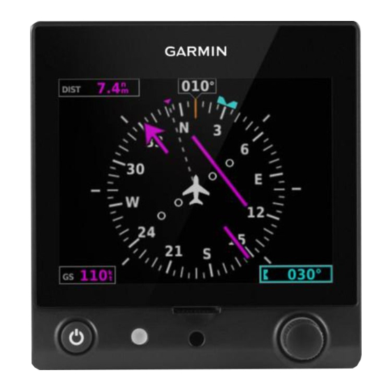
2.7 HSI PAGE NOTE: The HSI Page is accessible if a source of GPS or navigation data is configured (ARINC 429 or RS-232) AND the G5 is not configured as the #1 backup unit or a GDU is present. Distance To Waypoint... -
Page 120: Horizontal Situation Indicator (Hsi)
The bearing pointer never overrides the CDI and is visually separated from the CDI by a white ring (shown when the bearing pointer is selected but not necessarily visible due to data unavailability). Bearing Pointer HSI Page with Bearing Pointer Garmin G5 User's Manual 190-02072-00 Rev. B... - Page 121 CDI is not displayed. The CDI is capable of displaying two sources of navigation: GPS or NAV (VOR, localizer) depending on the external navigator(s) configured (refer to the G5 Installation Manual Section for more information). Color indicates the current navigation source: magenta (for GPS) or green (for VOR and LOC).
-
Page 122: Heading/Ground Track (Hsi Page)
Syncing to the current heading or ground track from the HSI page: Press the HDG Knob on the GMC 307. From the HSI Page, press and hold the Knob to sync to the current heading or ground track. Garmin G5 User's Manual 190-02072-00 Rev. B... -
Page 123: Navigation
Pilot's Guide 2.8 NAVIGATION NOTE: If the G5 is installed as part of a G3X/G3X Touch system, navigation data (both horizontal and vertical) will not appear on the G5 if any GDU displays are operational. 2.8.1 COURSE DEVIATION INDICATOR (CDI) The PFD Page displays the Course Deviation Indicator (CDI) below the slip/skid indicator. -
Page 124: Vertical Deviation Indicator And Vnav Indicator
NOTE: An external navigator (i.e. GTN/GNS, GNC 255, or SL30 Nav/Comm Transceiver) must be configured to receive glideslope and/or glidepath vertical deviation indications. Vertical Deviation Indicator Vertical Deviation Indicator Vertical Deviation Indicator Vertical Deviation Indicator Position (PFD Page) Position (HSI Page) Garmin G5 User's Manual 190-02072-00 Rev. B... - Page 125 A green diamond acts as the VDI Indicator, like a glideslope needle on a conventional indicator. If a localizer frequency is tuned and there is no glideslope signal, “NO GS” is annunciated. Vertical Deviation Indicator Vertical Deviation Indicator (Glideslope-ILS Source) 190-02072-00 Rev. B Garmin G5 User's Manual...
- Page 126 GPS approach. The glidepath is analogous to the glideslope for GPS approaches supporting WAAS vertical guidance (LNAV+V, L/VNAV, LPV). The Glidepath Indicator appears on the G5 as a magenta diamond. If the approach type downgrades past the final approach fix (FAF), “NO GP” is annunciated.
-
Page 127: Course Selection
VNAV Indicator 2.8.3 COURSE SELECTION When the G5 is receiving VOR or LOC data, a Course menu option is displayed. Setting the course for a VOR or localizer: 1) From the PFD Page, press the Knob to display the Menu. -
Page 128: Automatic Flight Control System (Optional)
Pilot’s Guide. NOTE: Refer to the approved Pilot’s Operating Handbook (POH) for emergency procedures. NOTE: The G5 does not support VOR, LOC, and GS modes. NOTE: A GMC controller is required for G5 AFCS functionality. 2.9.1 AFCS SYSTEM ARCHITECTURE An Automatic Flight Control System (AFCS) is typically comprised of two major components: A Flight Director (FD) and Autopilot servos. - Page 129 Dutch roll response. It also uses lateral acceleration to coordinate turns and reduce or eliminate the need for the pilot to use rudder pedal force to maintain coordinated flight during climbs and descents. 190-02072-00 Rev. B Garmin G5 User's Manual...
-
Page 130: Control Wheel Steering (Cws) (Optional)
The AFCS status box displays Autopilot (AP) and Flight Director (FD) mode annunciations on the PFD Page. Autopilot (AP) status is displayed on the far left of the G5 Autopilot Status Box. Lateral modes are displayed in the center, and vertical modes are displayed on the right. -
Page 131: G5 Afcs Configuration
Pilot's Guide 2.9.4 G5 AFCS CONFIGURATION The G5 can be configured as a standalone unit or as a backup unit for a G3X or G3X Touch system. When configured as a standalone unit with a GMC controller and GSA servos: •... -
Page 132: Afcs Operation
2.9.5 AFCS OPERATION NOTE: When the G5 is configured as part of a G3X/G3X Touch system, the G5 can be used to drive the autopilot and flight director only when all GDUs are removed from the network. AFCS functionality is distributed across the following Line Replaceable Units (LRUs): •... -
Page 133: Afcs Pre-Flight Actions (Standalone Installation)
2.9.6 AFCS PRE-FLIGHT ACTIONS (STANDALONE INSTALLATION) To ensure that the Automatic Flight Control System (AFCS) is operating properly prior to flight, perform the following Garmin recommended preflight checks. Before takeoff checklist: 1) Autopilot - ENGAGE (using AP/CWS button, or AP button on mode... -
Page 134: Afcs Controls
Command Bars. If the autopilot is engaged, the key is disabled. APR Key Selects/deselects Approach Mode (GP mode only) HDG Knob Selects the desired Heading* ALT SEL Knob Selects the desired Altitude setting* *GMC 307 only Garmin G5 User's Manual 190-02072-00 Rev. B... - Page 135 Pilot's Guide Active Mode GMC 305 AFCS Control Unit GMC 307 AFCS Control Unit 190-02072-00 Rev. B Garmin G5 User's Manual...
- Page 136 Pilot's Guide The following AFCS controls are located separately from the G5 and GMC 305/307 AFCS Control Unit: CWS/AP DISC Button An AP DISC/CWS Button is located on the pilot’s control (Autopilot Disconnect) stick. This button combines the functions of Autopilot Disconnect and Control Wheel Steering.
- Page 137 (GmC 305/307) nGaGinG the utoPiLot An initial press of the AP Key on the GMC 305/307 will activate the Flight Director and engage the autopilot in the default PIT and ROL modes. 190-02072-00 Rev. B Garmin G5 User's Manual...
- Page 138 3) Retrim the aircraft as needed. Substantial trim adjustment may be needed. 4) Pull the appropriate circuit breaker(s) to electrically isolate the servo and solenoid components. 5) Release the AP DISC Switch. Garmin G5 User's Manual 190-02072-00 Rev. B...
-
Page 139: Flight Director Operation
PFD Page. With the flight director active, the aircraft can be hand-flown to follow the path shown by the Command Bars. The Flight Director has the following maximum commands: pitch (-15°, +20°) and roll (30°) angles. 190-02072-00 Rev. B Garmin G5 User's Manual... - Page 140 *** HDG mode is only available when magnetic heading data is being received from an ADAHRS unit, when the G5 is installed as a backup unit in a G3X/G3X Touch system. Flight Director Activation (GMC 305/307) Garmin G5 User's Manual...
- Page 141 PFD Page. If the aircraft is being flown by hand, the command bars are displayed hollow. The Command Bars do not override the Aircraft Symbol. The Command Bars move together vertically to indicate pitch commands and bank left or right to indicate roll commands. 190-02072-00 Rev. B Garmin G5 User's Manual...
- Page 142 Command Bars (Single Cue Flight Director) Flight Director Flight Director (Dual Cue) If the attitude information being sent to the flight director becomes invalid or unavailable, the Command Bars are removed from the display. Garmin G5 User's Manual 190-02072-00 Rev. B...
- Page 143 Default Vertical Speed that is used for the initial climb or descent is set using a pair of fields that appear when Select VS Mode is selected. When Altitude Controls are set to Simplified, Altitude Hold (ALT) Mode behavior differs in the following ways: 190-02072-00 Rev. B Garmin G5 User's Manual...
- Page 144 Default Vertical Speed fields as described previously. • When Altitude Hold (ALT) Mode has captured the Selected Altitude, the vertical speed bug is removed and vertical speed adjustments have no effect. Garmin G5 User's Manual 190-02072-00 Rev. B...
-
Page 145: Vertical Modes
VS Key 100 fpm Speed climb/descend to the Selected Altitude Maintains the current aircraft Indicated airspeed in IAS while the IAS Key Airspeed 1 kt aircraft is climbing/descending (IAS) to the Selected Altitude 190-02072-00 Rev. B Garmin G5 User's Manual... - Page 146 * ALTS armed automatically when PIT, VS, IAS, or GA active, and under VNAV when Selected Altitude is to be captured instead of VNV Target Altitude ** TO and GA modes are only displayed when the G5 is configured as a backup unit in a G3X/G3X Touch system.
- Page 147 Hold the Control Wheel Steering (CWS) Button (if equipped, and the autopilot unit supports CWS), establish the desired pitch attitude, then release the CWS Button. Selected Altitude Selected Altitude Pitch Hold Capture Mode Mode Active Armed Pitch Hold & Selected Altitude Capture Modes 190-02072-00 Rev. B Garmin G5 User's Manual...
- Page 148 1) Press the Knob to display the Menu. 2) Select Altitude and use the Knob to change the Selected Altitude. Syncing to the current altitude: Press the Knob on the GMC 307. 1) Press the Knob to display the Menu. Garmin G5 User's Manual 190-02072-00 Rev. B...
- Page 149 (to the nearest 10 feet) as the Altitude Reference. Altitude Hold Mode active is indicated by a green ‘ALT’ annunciation in the G5 Autopilot Status Box. Altitude Hold Mode is automatically armed when in Selected Altitude Capture Mode.
- Page 150 Vertical Speed Indicator. A Vertical Speed Reference Bug corresponding to the Vertical Speed Reference is shown on the indicator. Vertical Speed Reference Vertical Speed Reference Vertical Speed Reference on PFD Page Garmin G5 User's Manual 190-02072-00 Rev. B...
- Page 151 Airspeed Reference along the airspeed tape. Engine power must be adjusted to allow the autopilot to fly the aircraft at a pitch attitude corresponding to the desired flight profile (climb or descent) while maintaining the Airspeed Reference. 190-02072-00 Rev. B Garmin G5 User's Manual...
- Page 152 CWS Button. Vertical Navigation (VNV) Mode is available for enroute/terminal cruise and descent operations any time that VNAV input data is being received. Vertical Navigation Mode Active Vertical Navigation Mode Garmin G5 User's Manual 190-02072-00 Rev. B...
- Page 153 1) When a flight plan is active, VNAV data is valid, and the VNV Key is selected, VNV mode is armed in preparation for descent path capture. ‘VNV’ is annunciated in white in the G5 Autopilot Status Box. 2) When a descent leg is captured (i.e., vertical deviation becomes valid), VNV Mode is activated and tracks the descent profile.
- Page 154 • The active waypoint is at or after the final approach fix (FAF). • Vertical deviation is valid. • The CDI is at less than full-scale deviation. • Automatic sequencing of waypoints has not been suspended. Garmin G5 User's Manual 190-02072-00 Rev. B...
- Page 155 Glidepath Mode GO AROUND (GA) AND TAKEOFF (TO) MODES NOTE: TO and GA modes are only available when the G5 is configured as a backup unit in a G3X/G3X Touch system. Go Around and Takeoff modes are coupled pitch and roll modes and are annunciated as both the vertical and lateral modes when active.
-
Page 156: Lateral Modes
Commands a constant pitch angle Go Around and wings level in the air * HDG, TO, and GA modes are only available when the G5 is configured as a backup unit in a G3X/ G3X Touch system. Flight Director Lateral Modes The CWS Button (if equipped) does not change lateral references for HDG or NAV modes. - Page 157 When operating in Roll Hold Mode, the roll reference can be adjusted in the following ways: • Hold the CWS Button (if equipped), establish the desired bank angle, then release the CWS Button. 190-02072-00 Rev. B Garmin G5 User's Manual...
- Page 158 Pilot's Guide HEADING SELECT MODE (HDG) NOTE: HDG mode is only available when the G5 is configured as a backup in a G3X/G3X Touch system and the G5 is receiving magnetic heading data from an ADAHRS unit. Heading Select Mode is activated by pressing the HDG Key. Heading Select Mode acquires and maintains the Selected Heading.
- Page 159 Bug is turned more than 180˚ from the present heading (e.g., a 270˚ turn to the right). However, Selected Ground Track changes of more than 330˚ at a time result in turn reversals. Track Mode Annunciation 190-02072-00 Rev. B Garmin G5 User's Manual...
- Page 160 If Navigation Mode is active and either of the following occur, the AFCS reverts to Roll Hold Mode (wings rolled level): • Active navigation source manually switched • Active flight plan is deleted • GPS reception is lost Garmin G5 User's Manual 190-02072-00 Rev. B...
- Page 161 . If not, press the CDI Key. lower-left corner 3) EXTERNAL NAVIGATOR: Select and activate the GPS approach using the PROC Key. 4) Press the NAV Key. 5) Adjust the aircraft’s pitch axis as required. 190-02072-00 Rev. B Garmin G5 User's Manual...
- Page 162 2) EXTERNAL NAVIGATOR: Ensure the ‘GPS’ indication is showing in the . If not, press the CDI Key. lower-left corner 3) EXTERNAL NAVIGATOR: Select and activate the GPS approach using the PROC Key. APR Key. 4) Press the Garmin G5 User's Manual 190-02072-00 Rev. B...
-
Page 163: System Messages
Unit temperature limit Unit is too hot or too cold exceeded Network address conflict Another G5 with the same address is detected on the network (most commonly a wiring error on one of the units) Communication error General communication error (most commonly... - Page 164 Pilot's Guide Message Comments Factory calibration data Unit calibration data not valid - return to Garmin invalid Magnetic field model Internal magnetic field database is out of date - database out of date software update required Using external GPS data GPS data from another network LRU is being used.
-
Page 165: Index
Secure Digital (SD) Cards 90 Glidepath Mode (GP) 142 Installing 90 Selected Altitude 135, 136, 138 Selected Altitude Capture Mode 135, Heading 95 136, 138, 143 Heading Select Mode 146, 147 Selected Heading 110, 146, 147 Index-1 190-02072-00 Rev. B Garmin G5 User's Manual... - Page 166 Initialization 90 Power-up 90 Takeoff Mode 143 Transponder Status Box 95 True Airspeed (TAS) 95 Vertical Deviation Indicator (VDI) 112 Vertical Speed Indicator (VSI) 103, 105, Vertical Speed Mode 138 Warranty C-10 Index-2 Garmin G5 User's Manual 190-02072-00 Rev. B...
- Page 167 Blank Page 190-02072-00 Rev. B Garmin G5 User's Manual...
- Page 168 Fax: +44 (0) 238 052 4004 Aviation Support: +44 (0) 370 850 1243 Garmin Corporation No. 68, Zhangshu 2nd Road Xizhi District, New Taipei City, Taiwan Tel: 34-93-357-2608 Fax: 34-93-429-4484 www.garmin.com 190-02072-00 Rev. B © 2016 Garmin Ltd. or its subsidiaries...