Garmin G5 Pilot's Manual
Electronic flight instrument
Hide thumbs
Also See for G5:
- Installation manual (285 pages) ,
- Install manual & pilot's manual (238 pages) ,
- User manual (168 pages)

Related Manuals for Garmin G5


Summary of Contents for Garmin G5
- Page 1 Garmin G5 Electronic Flight Instrument Part 23 AML STC Pilot’s Guide 190-01112-12 July 2016 Revision 1...
- Page 2 Garmin. Garmin hereby grants permission to download a single copy of this manual and of any revision to this manual onto a hard drive or other electronic storage medium to be viewed...
- Page 3 RECORD OF REVISIONS Revision Revision Date Description 7/21/16 Initial Release Garmin G5 Part 23 AML STC Pilot’s Guide 190-01112-12 Rev. 1 Page B...
- Page 4 Use of polarized eyewear may cause the display to appear dim or blank. NOTE All images used in this document are current at the time of publication but are subject to change and may not be up to date. Garmin G5 Part 23 AML STC Pilot’s Guide 190-01112-12 Rev. 1 Page i...
-
Page 5: Table Of Contents
2.3 Backlight Intensity ..........................5 3 ACCESSING FUNCTIONALITY ......................6 3.1 Pages ............................... 6 3.2 Menu ..............................6 3.3 PFD Page ............................7 4 SYSTEM MESSAGES ........................... 16 Garmin G5 Part 23 AML STC Pilot’s Guide 190-01112-12 Rev. 1 Page ii... -
Page 6: System Description
The G5 Electronic Flight Instrument contains integrated attitude/air data sensors that provide display of attitude and secondary display of air data information. The G5 features a bright, sunlight readable, 3.5-inch color display. In the case of aircraft power loss, the G5 battery sustains the G5 flight display with up to 4 hours of power. -
Page 7: Bezel Overview
From the Main Menu, turn the Knob to move the cursor to the desired menu item. Rotate to adjust the barometric setting. Turn to select the desired value when editing numeric data or selecting from a list. Garmin G5 Part 23 AML STC Pilot’s Guide 190-01112-12 Rev. 1 Page 2 of 16... -
Page 8: Microsd Cards
1.3 MicroSD Cards ™ ™ The G5 data card slot uses micro Secure Digital (SD) cards. The microSD card can be used for software updates and data logging. The maximum supported card size is 32G. ™ Installing a microSD Card: ™... -
Page 9: Operation
If the G5 senses that the attitude solution is valid, but not yet within the internal accuracy limits, "ALIGNING" is displayed. The displayed attitude information is still accurate and usable while this indication is shown. -
Page 10: Backlight Intensity
Attitude Aligning Keep Wings Level Indication If the G5 inertial sensors fail, “ATTITUDE FAIL” is displayed in addition to a red-X flag. No attitude information is displayed while this indication is shown. -
Page 11: Accessing Functionality
The G5 is in PFD page format only. PFD Page 3.2 Menu Press the Knob to access the G5 Menu. Navigate the menu by rotating the Knob and make selections by pressing the Knob. PFD Page Menu Garmin G5 Part 23 AML STC Pilot’s Guide 190-01112-12 Rev. -
Page 12: Pfd Page
3.3 PFD Page The G5 PFD Page displays a horizon, airspeed, attitude, altitude, and vertical speed. The following flight instruments and supplemental flight data are displayed on the PFD Page: G5 PFD Flight Instruments Airspeed Indicator Selected Altitude Bug Attitude Indicator... - Page 13 3.3.1 Airspeed Indicator NOTE: The G5 Vspeed Reference values depend upon the aircraft’s specific system configuration and may vary from the examples discussed in this section. The Airspeed Indicator displays airspeed on a rolling number gauge using a moving tape. The numeric labels and major tick marks on the moving tape are marked at intervals of 10 MPH or KT, as indicated at bottom of airspeed tape).
- Page 14 When airspeed is present, the Vspeeds configured are displayed at their respective locations to the right of the airspeed scale; otherwise, the Vspeeds are displayed at the bottom of the airspeed indicator. Vspeed References Vspeed References Garmin G5 Part 23 AML STC Pilot’s Guide 190-01112-12 Rev. 1 Page 9 of 16...
- Page 15 Slip/skid is indicated by the location of the ball. Attitude Indicator Roll Pointer Roll Scale Horizon Line Aircraft Symbol Slip/Skid Indicator Land Representation Pitch Scale Sky Representation Roll Scale Zero Garmin G5 Part 23 AML STC Pilot’s Guide 190-01112-12 Rev. 1 Page 10 of 16...
- Page 16 The barometric pressure setting is displayed below the Altimeter in inches of mercury (in Hg). Selecting the altimeter barometric pressure setting: Turn the Knob to set the barometric pressure. Garmin G5 Part 23 AML STC Pilot’s Guide 190-01112-12 Rev. 1...
- Page 17 Feet of the Selected Altitude), the Selected Altitude changes to yellow text on a black background, flashes for 5 seconds. Deviation of ±200 ft Altitude Alerting Visual Annunciation Garmin G5 Part 23 AML STC Pilot’s Guide 190-01112-12 Rev. 1 Page 12 of 16...
- Page 18 Turn Rate Trend Vector Turn Rate Indicator (Standard Rate Tick Marks) Turn Rate Indicator Garmin G5 Part 23 AML STC Pilot’s Guide 190-01112-12 Rev. 1 Page 13 of 16...
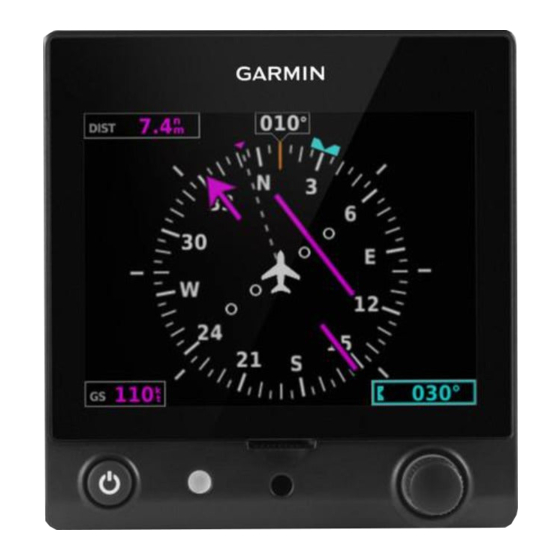
- Page 19 2) Select Track and press and hold the Knob to sync the selected ground track to the current ground track. Current Selected Ground Ground Track Track Bug Selected Ground Track Garmin G5 Part 23 AML STC Pilot’s Guide 190-01112-12 Rev. 1 Page 14 of 16...
- Page 20 21-40% 0-20% When the G5 is powered by the battery, the estimated time until the battery is empty is displayed in hours and minutes. Otherwise, the current charge level of the battery in percent is displayed as a numeric value.
-
Page 21: System Messages
Battery fault Battery is not present SYSTEM MESSAGES The following table shows G5 system messages that may appear along the bottom of the display. These messages remain while the condition persists or until cleared by pressing the knob. Message Meaning...