Garmin G5 Pilot's Manual
Electronic flight instrument for non-certified aircraft
Hide thumbs
Also See for G5:
- Installation manual (285 pages) ,
- Install manual & pilot's manual (238 pages) ,
- User manual (168 pages)
Table of Contents
Advertisement
Advertisement
Table of Contents

Related Manuals for Garmin G5


Summary of Contents for Garmin G5
- Page 1 G5 Electronic Flight Instrument Pilot's Guide for Non-Certified Aircraft...
- Page 2 Blank Page...
- Page 3 SYSTEM OVERVIEW FLIGHT INSTRUMENTS AFCS ADDITIONAL FEATURES INDEX...
- Page 4 Blank Page...
- Page 5 Garmin is a registered trademark of Garmin Ltd. or its subsidiaries. This trademark may not be ® used without the express permission of Garmin.
- Page 6 WARNING: To reduce the risk of unsafe operation, carefully review and understand all aspects of the G5 Install Manual & Pilot's Guide documentation and the Pilot’s Operating Handbook of the aircraft. Thoroughly practice basic operation prior to actual use.
- Page 7 FAA, FCC, and other applicable regulations. NOTE: The G5 may only be installed in type-certificated aircraft in accordance with Garmin STC SA01818WI. NOTE: The term LRU, as used throughout this manual is an abbreviation for Line Replaceable Unit.
- Page 8 Although unlikely, it may be possible for erroneous operation to occur without a fault indication shown by the G5. It is thus the responsibility of the pilot to detect such an occurrence by means of cross-checking with all redundant or correlated information available in the cockpit.
-
Page 9: Declaration Of Conformity
Warnings, Cautions & Notes DECLARATION OF CONFORMITY Hereby, Garmin declares that this product is in compliance with the Directive 2014/53/EU. The full text of the EU declaration of conformity is available at the following internet address www.garmin. com/compliance. This device complies with Part 15 of the FCC Rules. Operation is subject to the following two conditions: (1) this device may not cause harmful interference, and (2) this device must accept any interference received, including interference that may cause undesired operation. - Page 10 You further acknowledge that the structure, organization, and code of the Software are valuable trade secrets of Garmin and/or its third-party providers and that the Software in source code form remains a valuable trade secret of Garmin and/or its third-party providers.
- Page 11 Distributor warranties are only valid in the area of intended distribution. Devices purchased in the U.S. or Canada must be returned to the Garmin service center in the U.K., the U.S., Canada, or Taiwan for service.
- Page 12 Added support for multiple navigation sources Added 'Unable to Charge Battery' indication Added ability to configure Sky Pointer or Ground Pointer Other miscellaneous updates for Software Version 4.10 G5 Electronic Flight Instrument Pilot's Guide for Non-Certified Aircraft 190-02072-00 Rev. G...
-
Page 13: Table Of Contents
3.1.6 Control Wheel Steering (CWS) (Optional) ..............39 3.1.7 G5 AFCS Status Box ....................39 3.1.8 G5 AFCS Configuration..................... 40 3.1.9 AFCS Operation ......................40 3.1.10 AFCS PRE-FLIGHT Actions (Standalone Installation) ..........41 190-02072-00 Rev. G G5 Electronic Flight Instrument Pilot's Guide for Non-Certified Aircraft... - Page 14 Section 4 Additional Features ................... 73 4.1 Electronic Stability & Protection (ESP) ............... 73 4.1.1 Roll Engagement ...................... 75 4.1.2 Pitch Engagement ....................76 4.1.3 Airspeed Protection ....................78 Index ...........................Index-1 G5 Electronic Flight Instrument Pilot's Guide for Non-Certified Aircraft 190-02072-00 Rev. G...
- Page 15 Table of Contents 190-02072-00 Rev. G G5 Electronic Flight Instrument Pilot's Guide for Non-Certified Aircraft...
- Page 16 Table of Contents Blank Page G5 Electronic Flight Instrument Pilot's Guide for Non-Certified Aircraft 190-02072-00 Rev. G...
-
Page 17: Section 1 System Overview
3.5-inch color display which is sized to fit in a standard 3-1/8-inch instrument cutout. When installed as part of a G3X system, the G5 provides a redundant source of attitude and air data to the G3X displays, and additionally provides backup autopilot control allowing coupled GPS approaches to be flown or continued in the event of primary flight display is unavailability. -
Page 18: Micro -Sd ™ Cards
During system initialization, the G5 displays the message ‘ALIGNING’ over the attitude indicator. The G5 should display valid attitude typically within the first minute of power-up. The G5 can align itself both while taxiing and during level flight. G5 Electronic Flight Instrument Pilot's Guide for Non-Certified Aircraft... -
Page 19: Operation
Any failure of the inertial sensors results in loss of attitude and information (indicated by Red-X flags over the PFD attitude display). If the G5 senses that the attitude solution is valid, but not yet within the internal accuracy limits, "ALIGNING" is displayed. The G5 can align itself both while taxiing and during level flight. -
Page 20: G5 Heading
Magnetic heading is available in a standalone installation with a magnetometer, and when the G5 is configured as a backup in a G3X/G3X Touch system and the G5 is receiving magnetic heading data from an ADAHRS unit. If magnetic heading input data is not available, the G5 will display GPS-derived ground track instead. -
Page 21: Accessing Functionality
(if enabled in the system configuration). Refer to the Installation Manual section for more information. The G5 has two main pages, the HSI Page and the PFD Page. The HSI Page can be accessed from the PFD Page (unless it has been disabled in configuration). -
Page 22: Menu
System Overview 1.5.2 MENU Press the Knob to access the G5 Menu. Navigate the menu by rotating the Knob and make selections by pressing the Knob. Figure 1-5 PFD Page Menu Figure 1-6 HSI Page Menu G5 Electronic Flight Instrument Pilot's Guide for Non-Certified Aircraft... -
Page 23: Section 2 Flight Instruments
Flight Instruments SECTION 2 FLIGHT INSTRUMENTS 2.1 PFD PAGE The G5 PFD Page displays a horizon, airspeed, attitude, altitude, vertical speed, heading, and course deviation information. The following flight instruments and supplemental flight data are displayed on the PFD Page. -
Page 24: Airspeed Indicator
Selected Altitude Bug Battery Status Indicator 2.1.1 AIRSPEED INDICATOR NOTE: The G5 Vspeed Reference values depend upon the aircraft’s specific system configuration and may vary from the examples discussed in this sec- tion. The Airspeed Indicator displays airspeed on a rolling number gauge using a moving tape. - Page 25 Mach number (MMO). This is useful in aircraft where true airspeed or Mach number must be kept below a certain limit. If configured, the G5 can display V based on TAS or Mach in addition to IAS, which will cause the displayed value for V to be reduced at high altitudes.
- Page 26 Vspeed references including V , can be configured to display on the G5, refer to the Installation Manual section for more information. When airspeed is present, the Vspeeds configured are displayed at their respective locations to the right of the airspeed scale, otherwise the Vspeeds are displayed at the bottom of the airspeed indicator.
-
Page 27: Attitude Indicator
Sky Representation Roll Scale Zero Figure 2-4 Attitude Indicator Flight Director Figure 2-5 Attitude Indicator with Figure 2-6 Attitude Indicator with Flight Director (Single Cue) Flight Director (Dual Cue) 190-02072-00 Rev. G G5 Electronic Flight Instrument Pilot's Guide for Non-Certified Aircraft... - Page 28 The roll (bank angle) indication may be configured to be a Ground Pointer (default) or a Sky Pointer. Refer to the G5 Installation Manual for configuration information. The Ground Pointer configuration displays both the roll arc and the pitch ladder anchored to the horizon and the roll pointer beneath the roll arc pointing to the present roll angle.
-
Page 29: Altimeter
Selected Altitude exceeds the range shown on the tape, the bug appears at the corresponding edge of the tape. The Selected Altitude is synchronized between the G5 and the other displays in a G3X/G3X Touch system. Setting the selected altitude: Rotate the ALT SEL Knob on the GMC 307. -
Page 30: Barometric Pressure
The barometric pressure setting is displayed below the Altimeter in inches of mercury (in Hg) or hectopascals (hPa) when metric units are selected. The barometric pressure setting is synchronized between the G5 and the other displays in a G3X/G3X Touch system. -
Page 31: Turn Rate Indicator
10°. Major tick marks are at 5° intervals and minor tick marks at 1° intervals. The current track is represented by a magenta triangle. The Heading/ Ground Track Tape also displays the navigation course. 190-02072-00 Rev. G G5 Electronic Flight Instrument Pilot's Guide for Non-Certified Aircraft... - Page 32 When displaying the Selected Heading, a light blue bug on the tape corresponds to the Selected Heading. When displaying Ground Track, a magenta bug is displayed on the tape. The selected heading is synchronized between the G5 and the other displays in a G3X/G3X Touch system.
-
Page 33: Vertical Speed Indicator (Vsi)
Vertical Speed Indicator can be configured to display ± 1500 fpm, ± 2000 fpm, or ± 3000 fpm (refer to the Installation Manual section for more information). Current Vertical Speed Figure 2-14 Vertical Speed Indicator 190-02072-00 Rev. G G5 Electronic Flight Instrument Pilot's Guide for Non-Certified Aircraft... -
Page 34: Pfd Pitch Attitude Offset
The pitch attitude can be adjusted as much as ± 5°. The pitch offset is synchronized between the G5 and the other displays in a G3X/G3X Touch system. This function can be disabled in configuration mode. -
Page 35: Battery Status Indicator
1:31 0%-20% 0:38 When the G5 is powered by the battery, the estimated time until the battery is empty is displayed. Otherwise, the current charge level of the battery in percent is displayed as a numeric value. When the G5 is connected to external power and the battery is being charged, a lightning bolt symbol appears over the battery icon. -
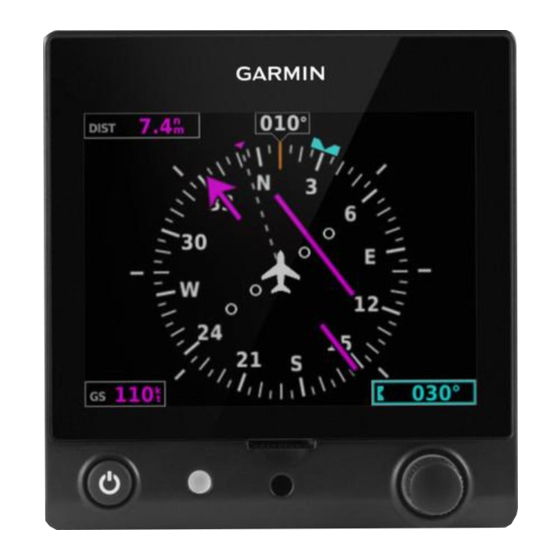
Page 36: Hsi Page
Selected Heading or Current Heading/Ground Navigation Source Ground Track Track Aircraft Symbol OBS Annunciator Current Track Course Deviation Indica- Navigator Messages tor (CDI) Figure 2-16 Horizontal Situation Indicator (HSI) G5 Electronic Flight Instrument Pilot's Guide for Non-Certified Aircraft 190-02072-00 Rev. G... -
Page 37: Horizontal Situation Indicator (Hsi)
Pending Nav Message GPS Dead-Reckoning Mode Waypoint Arrival NOTE: The VFR CDI Scale is displayed when the G5 is connected to a GPS navigator via RS-232 only, or if ARINC 429 GPS navigation data is unavailable. 2.2.1 HORIZONTAL SITUATION INDICATOR (HSI) The Horizontal Situation Indicator (HSI) on the HSI Page displays a rotating compass card in a heading-up orientation. - Page 38 1) From the HSI Page, press the Knob to display the Menu. 2) Turn the Knob to highlight Bearing Pointer. 3) Press the Knob to enable or disable the Bearing Pointer. G5 Electronic Flight Instrument Pilot's Guide for Non-Certified Aircraft 190-02072-00 Rev. G...
- Page 39 CDI is not displayed. The CDI is capable of displaying multiple sources of navigation (GPS, VLOC, or both) depending on the external navigator(s) configured (refer to the G5 Installation Manual Section for more information). Color indicates the current navigation source: magenta (for GPS) or green (for VOR and LOC).
-
Page 40: Heading/Ground Track (Hsi Page)
Syncing to the current heading or ground track from the HSI page: Press the HDG Knob on the GMC 307. From the HSI Page, press and hold the Knob to sync to the current heading or ground track. G5 Electronic Flight Instrument Pilot's Guide for Non-Certified Aircraft 190-02072-00 Rev. G... -
Page 41: Navigation
Flight Instruments 2.3 NAVIGATION A G5 installed as part of a G3X system with multiple navigation sources will only display data from the #1 navigation source. If the navigation source is a GNS/GTN unit, both GPS and VLOC data can be displayed. Displayed navigation information is also dependent upon the selection on the navigation configuration page. -
Page 42: Course Deviation Indicator (Cdi)
CDI is not displayed. The CDI is capable of displaying multiple sources of navigation (GPS, VLOC, or both) depending on the external navigator(s) configured (refer to the G5 Installation Manual Section for more information). Color indicates the current navigation source: magenta (for GPS) or green (for VOR and LOC). - Page 43 Use the associated external navigator to toggle between GPS and VOR/LOC source types. Refer to the appropriate external navigator Pilot's Guide for more information. Changing the navigation source on the G5 (GPS, VOR, LOC, or VLOC): Refer to the G5 Installation Manual for information on configuring multiple navigation sources.
-
Page 44: Vertical Deviation Indicator And Vnav Indicator
Transceiver) must be configured to receive glideslope and/or glidepath vertical deviation indications. Vertical Deviation Indicator Vertical Deviation Indicator Figure 2-22 Vertical Deviation Figure 2-23 Vertical Deviation Indicator Position (PFD Page) Indicator Position (HSI Page) G5 Electronic Flight Instrument Pilot's Guide for Non-Certified Aircraft 190-02072-00 Rev. G... - Page 45 A green diamond acts as the VDI Indicator, like a glideslope needle on a conventional indicator. If a localizer frequency is tuned and there is no glideslope signal, “NO GS” is annunciated. Vertical Deviation Indicator Figure 2-24 Vertical Deviation Indicator (Glideslope-ILS Source) 190-02072-00 Rev. G G5 Electronic Flight Instrument Pilot's Guide for Non-Certified Aircraft...
- Page 46 GPS approach. The glidepath is analogous to the glideslope for GPS approaches supporting WAAS vertical guidance (LNAV+V, L/VNAV, LPV). The Glidepath Indicator appears on the G5 as a magenta diamond. If the approach type downgrades past the final approach fix (FAF), “NO GP” is annunciated.
-
Page 47: Vnav Indicator
Flight Instruments 2.3.2.3 VNAV INDICATOR NOTE: VNAV deviation is only displayed when the G5 is receiving NMEA RS-232 data from a portable GPS. The magenta chevron (VNAV Indicator) to the left of the altimeter on the Vertical Deviation Scale displays the VNAV profile. -
Page 48: Course Selection
Flight Instruments 2.3.3 COURSE SELECTION When the G5 is receiving VOR, LOC, or GPS data, a Course menu option is displayed. Setting the course for a VOR or localizer: 1) From the PFD Page, press the Knob to display the Menu. -
Page 49: Section 3 Automatic Flight Control System (Optional)
Pilot’s Guide. NOTE: Refer to the approved Pilot’s Operating Handbook (POH) for emergency procedures. NOTE: A GMC controller is required for G5 AFCS functionality. 3.1 AFCS SYSTEM ARCHITECTURE An Automatic Flight Control System (AFCS) is typically comprised of two major components: A Flight Director (FD) and Autopilot servos. -
Page 50: Flight Control
Dutch roll response. It also uses lateral acceleration to coordinate turns and reduce or eliminate the need for the pilot to use rudder pedal force to maintain coordinated flight during climbs and descents. G5 Electronic Flight Instrument Pilot's Guide for Non-Certified Aircraft 190-02072-00 Rev. G... -
Page 51: Control Wheel Steering (Cws) (Optional)
The G5 autopilot control is synchronized to the aircraft attitude during Control Wheel Steering. The green ‘AP’ annunciation is temporarily replaced by a white ‘CW’ for the duration of Control Wheel Steering maneuvers. -
Page 52: G5 Afcs Configuration
AFCS 3.1.8 G5 AFCS CONFIGURATION The G5 can be configured as a standalone unit or as a backup unit for a G3X or G3X Touch system. When configured as a standalone unit with a GMC controller and GSA servos: • The G5 supports the following modes: LVL, PIT, ROL, HDG... -
Page 53: Afcs Pre-Flight Actions (Standalone Installation)
• Manual Electric Trim (MET) — Manual electric trim may provide trim capability for any properly configured axis (pitch, roll, or yaw) when the autopilot is not engaged. NOTE: Refer to the G5 Installation Manual Section for information on install- ing and configuring the G5 Integrated Autopilot Interface. -
Page 54: G5 Electronic Flight Instrument Pilot's Guide For Non-Certified Aircraft
APR Key Selects/deselects Approach Mode (GP mode only) HDG Knob Selects the desired Heading* ALT SEL Knob Selects the desired Altitude setting* *GMC 307 only G5 Electronic Flight Instrument Pilot's Guide for Non-Certified Aircraft 190-02072-00 Rev. G... - Page 55 AFCS Active Mode Figure 3-2 GMC 305 AFCS Control Unit Figure 3-3 GMC 307 AFCS Control Unit 190-02072-00 Rev. G G5 Electronic Flight Instrument Pilot's Guide for Non-Certified Aircraft...
- Page 56 AFCS The following AFCS controls are located separately from the G5 and GMC 305/307 AFCS Control Unit: Table 3-2 Other AFCS Controls CWS/AP DISC Button An AP DISC/CWS Button is located on the pilot’s control (Autopilot Disconnect) stick. This button combines the functions of Autopilot Disconnect and Control Wheel Steering.
-
Page 57: Engaging The Autopilot
An initial press of the AP Key on the GMC 305/307 will activate the Flight Director and engage the autopilot in the default PIT and ROL modes. 190-02072-00 Rev. G G5 Electronic Flight Instrument Pilot's Guide for Non-Certified Aircraft... -
Page 58: Disengaging The Autopilot
3) Retrim the aircraft as needed. Substantial trim adjustment may be needed. 4) Pull the appropriate circuit breaker(s) to electrically isolate the servo and solenoid components. 5) Release the AP DISC Switch. G5 Electronic Flight Instrument Pilot's Guide for Non-Certified Aircraft 190-02072-00 Rev. G... -
Page 59: Flight Director Operation
Command Bars. The Flight Director has the following maximum commands: pitch (-15°, +20°) and roll (30°) angles. 190-02072-00 Rev. G G5 Electronic Flight Instrument Pilot's Guide for Non-Certified Aircraft... -
Page 60: Activating The Flight Director
*** HDG mode is only available when magnetic heading data is being received from an ADAHRS unit, when the G5 is installed as a backup unit in a G3X/G3X Touch system. G5 Electronic Flight Instrument Pilot's Guide for Non-Certified Aircraft... -
Page 61: Flight Director Modes
If after 10 seconds no action is taken, the flashing annunciation stops. The flight director is automatically disabled if the attitude information required to compute the default flight director modes becomes invalid or unavailable. 190-02072-00 Rev. G G5 Electronic Flight Instrument Pilot's Guide for Non-Certified Aircraft... -
Page 62: Command Bars
Figure 3-5 Flight Director (Dual Cue) If the attitude information being sent to the flight director becomes invalid or unavailable, the Command Bars are removed from the display. G5 Electronic Flight Instrument Pilot's Guide for Non-Certified Aircraft 190-02072-00 Rev. G... - Page 63 Select VS Mode is selected. When Altitude Controls are set to Simplified, Altitude Hold (ALT) Mode behavior differs in the following ways: 190-02072-00 Rev. G G5 Electronic Flight Instrument Pilot's Guide for Non-Certified Aircraft...
-
Page 64: Vertical Modes
Speed, Indicated Airspeed, or Altitude Hold modes. Increments of change of values for each of these references using the NOSE UP/DN Wheel, are also listed in the table. G5 Electronic Flight Instrument Pilot's Guide for Non-Certified Aircraft 190-02072-00 Rev. G... - Page 65 * ALTS armed automatically when PIT, VS, IAS, or GA active, and under VNAV when Selected Altitude is to be captured instead of VNV Target Altitude ** TO and GA modes are only displayed when the G5 is configured as a backup unit in a G3X/G3X Touch system.
- Page 66 CWS), establish the desired pitch attitude, then release the CWS Button. Selected Altitude Capture Mode Pitch Hold Armed Mode Active Selected Altitude Figure 3-6 Pitch Hold & Selected Altitude Capture Modes G5 Electronic Flight Instrument Pilot's Guide for Non-Certified Aircraft 190-02072-00 Rev. G...
-
Page 67: Setting The Selected Altitude
Press the Knob on the GMC 307. 1) Press the Knob to display the Menu. 2) Select Altitude and press and hold the Knob to sync the Selected Altitude to the current altitude 190-02072-00 Rev. G G5 Electronic Flight Instrument Pilot's Guide for Non-Certified Aircraft... - Page 68 Altitude Hold Mode can be activated by pressing the ALT Key; the AFCS maintains the current aircraft altitude (to the nearest 10 feet) as the Altitude Reference. Altitude Hold Mode active is indicated by a green ‘ALT’ annunciation in the G5 Autopilot Status Box.
- Page 69 Vertical Speed Indicator. A Vertical Speed Reference Bug corresponding to the Vertical Speed Reference is shown on the indicator. Vertical Speed Reference Bug Vertical Speed Reference Figure 3-9 Vertical Speed Reference on PFD Page 190-02072-00 Rev. G G5 Electronic Flight Instrument Pilot's Guide for Non-Certified Aircraft...
- Page 70 Engine power must be adjusted to allow the autopilot to fly the aircraft at a pitch attitude corresponding to the desired flight profile (climb or descent) while maintaining the Airspeed Reference. G5 Electronic Flight Instrument Pilot's Guide for Non-Certified Aircraft 190-02072-00 Rev. G...
- Page 71 Vertical Navigation (VNV) Mode is available for enroute/terminal cruise and descent operations any time that VNAV input data is being received. Vertical Navigation Mode Active Figure 3-12 Vertical Navigation Mode 190-02072-00 Rev. G G5 Electronic Flight Instrument Pilot's Guide for Non-Certified Aircraft...
- Page 72 • Vertical deviation becomes invalid (the Deviation Indicator is removed from the PFD Page). Following a reversion to Pitch Hold Mode, VNV Mode becomes armed to allow for possible profile recapture. G5 Electronic Flight Instrument Pilot's Guide for Non-Certified Aircraft 190-02072-00 Rev. G...
- Page 73 • Vertical deviation is valid. • The CDI is at less than full-scale deviation. • Automatic sequencing of waypoints has not been suspended. Glidepath Mode Active Figure 3-13 Glidepath Mode 190-02072-00 Rev. G G5 Electronic Flight Instrument Pilot's Guide for Non-Certified Aircraft...
- Page 74 AFCS 3.1.13.8 GO AROUND (GA) AND TAKEOFF (TO) MODES NOTE: TO and GA modes are only available when the G5 is configured as a backup unit in a G3X/G3X Touch system. Go Around and Takeoff modes are coupled pitch and roll modes and are annunciated as both the vertical and lateral modes when active.
-
Page 75: Lateral Modes
Commands a constant pitch Go Around angle and wings level in the air * TO, and GA modes are only available when the G5 is configured as a backup unit in a G3X/G3X Touch system. 190-02072-00 Rev. G G5 Electronic Flight Instrument Pilot's Guide for Non-Certified Aircraft... - Page 76 When operating in Roll Hold Mode, the roll reference can be adjusted in the following ways: • Hold the CWS Button (if equipped), establish the desired bank angle, then release the CWS Button. G5 Electronic Flight Instrument Pilot's Guide for Non-Certified Aircraft 190-02072-00 Rev. G...
- Page 77 3.1.14.2 HEADING SELECT MODE (HDG) NOTE: HDG mode is available in a standalone installation with a magnetom- eter and when the G5 is configured as a backup in a G3X/G3X Touch system and the G5 is receiving magnetic heading data from an ADAHRS unit.
- Page 78 180˚ from the present heading (e.g., a 270˚ turn to the right). However, Selected Ground Track changes of more than 330˚ at a time result in turn reversals. Figure 3-16 Track Mode Annunciation G5 Electronic Flight Instrument Pilot's Guide for Non-Certified Aircraft 190-02072-00 Rev. G...
- Page 79 If Navigation Mode is active and either of the following occur, the AFCS reverts to Roll Hold Mode (wings rolled level): • Active navigation source manually switched • Active flight plan is deleted • GPS reception is lost 190-02072-00 Rev. G G5 Electronic Flight Instrument Pilot's Guide for Non-Certified Aircraft...
- Page 80 3) EXTERNAL NAVIGATOR: Select and activate the GPS approach using the PROC Key. 4) Press the NAV Key. 5) Adjust the aircraft’s pitch axis as required. G5 Electronic Flight Instrument Pilot's Guide for Non-Certified Aircraft 190-02072-00 Rev. G...
- Page 81 2) EXTERNAL NAVIGATOR: Ensure the ‘GPS’ indication is showing in the . If not, press the CDI Key. lower-left corner 3) EXTERNAL NAVIGATOR: Select and activate the GPS approach using the PROC Key. APR Key. 4) Press the 190-02072-00 Rev. G G5 Electronic Flight Instrument Pilot's Guide for Non-Certified Aircraft...
- Page 82 LVL Key is pressed all armed and active modes are cancelled and the autopilot and flight director revert to LVL mode for pitch and roll. While in level mode, all other modes are available by pressing the corresponding button. G5 Electronic Flight Instrument Pilot's Guide for Non-Certified Aircraft 190-02072-00 Rev. G...
-
Page 83: System Messages
Unit temperature limit Unit is too hot or too cold exceeded Network address conflict Another G5 with the same address is detected on the network (most commonly a wiring error on one of the units) Communication error General communication error (most commonly... -
Page 84: Afcs Alerts (Optional)
Autopilot unit will raise the nose to limit the MAX SPEED Protection aircraft’s speed. Low speed Autopilot unit will lower the nose to prevent MIN SPEED Protection the aircraft’s speed from decreasing. Table 3-12 Speed Alerts G5 Electronic Flight Instrument Pilot's Guide for Non-Certified Aircraft 190-02072-00 Rev. G... -
Page 85: Section 4 Additional Features
Also note that Level mode as activated by ESP is different than manually selected Level mode. Manually selected Level mode is not limited by altitude at all. 190-02072-00 Rev. G G5 Electronic Flight Instrument Pilot's Guide for Non-Certified Aircraft... - Page 86 3) Press the Knob to enable or disable ESP. ESP Roll Engage- ment Indication (ESP NOT Engaged) Touch To PDF Page Enable/ Menu Disable ESP Figure 4-1 AFCS (ESP Enabled) G5 Electronic Flight Instrument Pilot's Guide for Non-Certified Aircraft 190-02072-00 Rev. G...
-
Page 87: Roll Engagement
(ESP Enabled but NOT Engaged) ESP Disengage (30º) ESP Engage (45º)(Configurable) (15º < Configured Bank Limit) Aircraft Roll Attitude = 35º Figure 4-3 Roll Increasing to ESP Engagement 190-02072-00 Rev. G G5 Electronic Flight Instrument Pilot's Guide for Non-Certified Aircraft... -
Page 88: Pitch Engagement
The opposing force increases or decreases depending on the pitch angle and the direction of pitch travel. This force is intended to encourage movement in the pitch axis in the direction of the normal pitch attitude range for the aircraft. G5 Electronic Flight Instrument Pilot's Guide for Non-Certified Aircraft 190-02072-00 Rev. G... - Page 89 30˚ 30˚ 35˚ 35˚ 40˚ 40˚ 45˚ 45˚ 50˚ 50˚ Figure 4-7 ESP Pitch Operating Range When Engaged (Force Increases as Pitch Increases & Decreases as Pitch Decreases) 190-02072-00 Rev. G G5 Electronic Flight Instrument Pilot's Guide for Non-Certified Aircraft...
-
Page 90: Airspeed Protection
ESP applying force to raise or lower the nose of the aircraft. When the high or low airspeed condition is remedied, ESP force is no longer applied. Figure 4-8 ESP Engaged (Low Airspeed) G5 Electronic Flight Instrument Pilot's Guide for Non-Certified Aircraft 190-02072-00 Rev. G... - Page 91 57, 62 Selected Heading 28, 65, 66 Glidepath Mode (GP) 61 System Annunciations 7 Functionality 9 Heading 12 Initialization 6 Heading Select Mode 65, 66 Power-up 6 Index-1 190-02072-00 Rev. G G5 Electronic Flight Instrument Pilot's Guide for Non-Certified Aircraft...
-
Page 92: Index
Index Takeoff Mode 62 Transponder Status Box 12 True Airspeed (TAS) 12 Vertical Deviation Indicator (VDI) 32 Vertical Speed Indicator (VSI) 21, 30 Vertical Speed Mode 57 Index-2 G5 Electronic Flight Instrument Pilot's Guide for Non-Certified Aircraft 190-02072-00 Rev. G... - Page 93 Blank Page 190-02072-00 Rev. G G5 Electronic Flight Instrument Pilot's Guide for Non-Certified Aircraft...
- Page 94 Garmin (Europe) Ltd. Liberty House, Hounsdown Business Park Southampton, Hampshire SO40 9LR U.K. Garmin Corporation No. 68, Zhangshu 2nd Road Xizhi District, New Taipei City, Taiwan Contact Garmin Product Support at www.flygarmin.com 190-02072-00 Rev. G © 2017 Garmin Ltd. or its subsidiaries...