Garmin G5 Pilot's Manual
Electronic flight instrument for certified aircraft (includes the gfc 500)
Hide thumbs
Also See for G5:
- Installation manual (285 pages) ,
- Install manual & pilot's manual (238 pages) ,
- User manual (168 pages)

Related Manuals for Garmin G5


Summary of Contents for Garmin G5
- Page 1 G5 Electronic Flight Instrument Pilot's Guide for Certified Aircraft (includes the GFC 500)
- Page 3 SYSTEM OVERVIEW FLIGHT INSTRUMENTS AFCS ADDITIONAL FEATURES INDEX...
- Page 4 Blank Page...
- Page 5 Garmin is a registered trademark of Garmin Ltd. or its subsidiaries. This trademark may not be ® used without the express permission of Garmin.
- Page 6 Pilot's Guide. Thoroughly practice basic operation prior to actual use. During flight operations, carefully compare indications from the G5 to all available flight displays. For safety purposes, always resolve any discrepancies. WARNING: The altitude calculated by the G5 internal GPS receiver is geometric height above Mean Sea Level and could vary significantly from the altitude displayed by pressure altimeters.
- Page 7 FAA, FCC, and other applicable regulations. NOTE: The G5 may only be installed in type-certificated aircraft in accordance with Garmin STC SA01818WI. NOTE: The term LRU, as used throughout this manual is an abbreviation for Line Replaceable Unit.
- Page 8 Although unlikely, it may be possible for erroneous operation to occur without a fault indication shown by the G5. It is thus the responsibility of the pilot to detect such an occurrence by means of cross-checking with all redundant or correlated information available in the cockpit.
- Page 9 DECLARATION OF CONFORMITY Hereby, Garmin declares that this product is in compliance with the Directive 2014/53/EU. The full text of the EU declaration of conformity is available at the following internet address www.garmin. com/compliance. This device complies with Part 15 of the FCC Rules. Operation is subject to the following two conditions: (1) this device may not cause harmful interference, and (2) this device must accept any interference received, including interference that may cause undesired operation.
- Page 10 (iv) damage caused by service performed by anyone who is not an authorized service provider of Garmin; or (v) damage to a product that has been modified or altered without the written permission of Garmin. In addition, Garmin reserves the right to refuse warranty claims against products or services that are obtained and/or used in contravention of the laws of any country.
- Page 11 Distributor warranties are only valid in the area of intended distribution. Devices purchased in the U.S. or Canada must be returned to the Garmin service center in the U.K., the U.S., Canada, or Taiwan for service.
- Page 12 Updated printing instructions July, 2018 Added VNAV display capability July, 2019 Added GAD 13 functionality Updated images throughout August, 2019 Clerical corrections and clarifications January, 2020 Updated VNAV functionality G5 Electronic Flight Instrument Pilot's Guide for Certified Aircraft 190-01112-12 Rev. F...
-
Page 13: Table Of Contents
3.2.2 Flight Control ......................38 3.2.3 Pitch Axis and Trim ....................38 3.2.4 Roll Axis ........................38 3.2.5 Yaw Axis ........................38 3.2.6 G5 AFCS Status Box ....................39 190-01112-12 Rev. F G5 Electronic Flight Instrument Pilot's Guide for Certified Aircraft... - Page 14 3.5.3 Airspeed Protection (GFC 500 Only) ................75 Section 4 Additional Features ................... 77 4.1 GPS Steering (GPSS) ...................... 77 4.1.1 GAD 29B (Optional) ....................77 4.2 GAD 13 (Optional) ......................80 G5 Electronic Flight Instrument Pilot's Guide for Certified Aircraft 190-01112-12 Rev. F...
-
Page 15: Section 1 System Overview
The G5 can also be interfaced to an external sensor to provide heading information. The G5 features a bright, sunlight readable, 3.5-inch color display. In the case of aircraft power loss, the G5 battery sustains the G5 flight display with up to 4 hours of power. -
Page 16: Micro Sd ™ Cards
Table 1-1 G5 Controls CARDS ™ micro The G5 data card slot uses micro Secure Digital (SD) cards. The microSD card can ™ be used for software updates and data logging. The maximum supported card size is 32GB. -
Page 17: Applying System Power
During system initialization, the G5 displays the message ‘ALIGNING’ over the attitude indicator. The G5 should display valid attitude typically within the first minute of applying power. The G5 can align itself both while taxiing and during level flight. 1.4 OPERATION 1.4.1 G5 ANNUNCIATIONS... - Page 18 The G5 should display valid attitude within the first minute of applying power. If the G5 senses the attitude solution is valid, but not yet within the internal accuracy limits, "ALIGNING" is displayed. The displayed attitude information is still accurate and usable while this indication is shown.
- Page 19 Figure 1-9 Heading/Track Fail (PFD Page) Figure 1-10 Heading/Track Fail (HSI Page) The G5 corrects for shifts and variations in the Earth’s magnetic field by applying the Magnetic Field Variation Database. The Magnetic Field Variation Database is derived from the International Geomagnetic Reference Field (IGRF). The IGRF is a mathematical model that describes the Earth’s main magnetic field and its annual...
-
Page 20: Backlight Intensity
(if enabled in the system configuration). Refer to the Installation Manual for more information. The G5 has two main pages, the HSI Page and the PFD Page. The HSI Page can be accessed from the PFD Page (unless it has been disabled in configuration). -
Page 21: Menu
1) From the PFD Page press the Selection Knob to display the Menu. 2) Use the Selection Knob to select HSI. NOTE: The G5 can be configured to display the PFD or HSI page when power is applied (if allowed by the current system configuration). Refer to the Installation Manual for more information. -
Page 22: Messages
3) Press the Selection Knob to select Message. A list of messages is displayed. Message Details Message [!] Indication Menu Option Figure 1-19 Messages [!] Figure 1-18 Message [!] Displayed (PFD Page) Menu Option (PFD Page) G5 Electronic Flight Instrument Pilot's Guide for Certified Aircraft 190-01112-12 Rev. F... -
Page 23: System Messages
System Overview 1.6.1 SYSTEM MESSAGES The following table describes G5 system messages that may appear. System messages are displayed in white text. Table 1-2 System Messages Message Meaning External Power Lost Aircraft power has been removed from the G5. Critical battery fault! - Page 24 Not receiving RS-232 data The G5 is not receiving RS-232 data from the GPS navigator – system needs service. Not receiving ARINC 429 data The G5 is not receiving ARINC 429 data from the navigation source – system needs service. GPS receiver fault The G5 on-board GPS receiver has a fault.
-
Page 25: Section 2 Flight Instruments
Flight Instruments SECTION 2 FLIGHT INSTRUMENTS 2.1 PFD PAGE The G5 PFD Page displays a horizon, airspeed, attitude, altitude, vertical speed, heading, and course deviation information. The following flight instruments and supplemental flight data are displayed on the PFD Page. -
Page 26: Airspeed Indicator
Flight Instruments 2.1.1 AIRSPEED INDICATOR NOTE: The G5 Vspeed Reference values depend upon the aircraft’s specific system configuration and may vary from the examples discussed in this sec- tion. The Airspeed Indicator displays airspeed on a rolling number gauge using a moving tape. - Page 27 When airspeed is present, the configured Vspeeds are displayed at their respective locations to the right of the airspeed scale, otherwise the Vspeeds are displayed at the bottom of the airspeed indicator. Vspeed References Figure 2-3 Vspeed References 190-01112-12 Rev. F G5 Electronic Flight Instrument Pilot's Guide for Certified Aircraft...
-
Page 28: Attitude Indicator
Sky Representation Roll Scale Zero Figure 2-4 Attitude Indicator Flight Director Figure 2-5 Attitude Indicator with Figure 2-6 Attitude Indicator with Flight Director (Single Cue) Flight Director (Dual Cue) G5 Electronic Flight Instrument Pilot's Guide for Certified Aircraft 190-01112-12 Rev. F... - Page 29 The roll (bank angle) indication may be configured to be a Ground Pointer (default) or a Sky Pointer. Refer to the G5 Installation Manual for configuration information. The Ground Pointer configuration displays both the roll arc and the pitch scale anchored to the horizon and the roll pointer beneath the roll arc pointing to the present roll angle.
-
Page 30: Altimeter
2) Select Altitude and press and hold the Selection Knob to sync the Selected Altitude to the current altitude. Selected Altitude Current Altitude Selected Altitude Bug Barometric Setting Figure 2-9 Altimeter G5 Electronic Flight Instrument Pilot's Guide for Certified Aircraft 190-01112-12 Rev. F... - Page 31 (±200 Feet of the Selected Altitude), the Selected Altitude changes to yellow text on a black background, flashes for 5 seconds. Selected Altitude Indicates Deviation of ±200 feet From Current Altitude Current Altitude Figure 2-10 Altitude Alerting Visual Annunciation 190-01112-12 Rev. F G5 Electronic Flight Instrument Pilot's Guide for Certified Aircraft...
-
Page 32: Turn Rate Indicator
When displaying the Selected Heading, a cyan bug on the tape corresponds to the Selected Heading. When displaying Ground Track, a magenta bug is displayed on the tape. The heading bug turns hollow when GPSS is selected. G5 Electronic Flight Instrument Pilot's Guide for Certified Aircraft 190-01112-12 Rev. F... - Page 33 2) Select Heading or Track and press and hold the Selection Knob to sync the selected heading or ground track to the current heading or ground track. Current Heading Selected Heading Bug Ground Track Figure 2-12 PFD Page - Selected Heading 190-01112-12 Rev. F G5 Electronic Flight Instrument Pilot's Guide for Certified Aircraft...
-
Page 34: Vertical Speed Indicator (Vsi)
100 feet. The current vertical speed is displayed using a white arrow along the tape. Current Vertical Speed Figure 2-14 Vertical Speed Indicator G5 Electronic Flight Instrument Pilot's Guide for Certified Aircraft 190-01112-12 Rev. F... -
Page 35: Battery Status Indicator
When the G5 is powered by the aircraft electrical bus, the battery status indicator can be displayed by pressing the G5 Power Button. When the G5 is powered by the battery, the battery status indicator is displayed automatically. This indicator shows the estimated percent charge of the battery. -
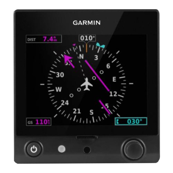
Page 36: Hsi Page
2.2 HSI PAGE NOTE: The HSI Page can be configured as disabled in configuration mode. The G5 HSI Page displays a rotating compass card in a heading-up orientation. Letters indicate the cardinal points and numeric labels occur every 30˚. Major tick marks are at 10˚... - Page 37 Pending Nav Message GPS Dead-Reckoning Mode Waypoint Arrival NOTE: The VFR CDI Scale is displayed when the G5 is connected to a GPS navigator via RS-232 only, or if ARINC 429 GPS navigation data is unavailable. 190-01112-12 Rev. F G5 Electronic Flight Instrument Pilot's Guide for Certified Aircraft...
-
Page 38: Horizontal Situation Indicator (Hsi)
Figure 2-16 Horizontal Situation Indicator (HSI) - Expanded Displaying the HSI page from the PFD page: 1) From the PFD Page press the Selection Knob to display the Menu. 2) Select HSI. G5 Electronic Flight Instrument Pilot's Guide for Certified Aircraft 190-01112-12 Rev. F... - Page 39 2) Turn the Selection Knob to highlight Setup. 3) Press the Selection Knob and turn to highlight the Bearing Pointer 1 setting. Figure 2-19 Setup Menu Figure 2-20 Bearing Pointer Setting 190-01112-12 Rev. F G5 Electronic Flight Instrument Pilot's Guide for Certified Aircraft...
-
Page 40: Heading/Ground Track (Hsi Page)
Syncing to the current heading or ground track from the HSI page: Press the HDG Knob on the GMC 507. From the HSI Page, press and hold the Selection Knob to sync to the current heading or ground track. G5 Electronic Flight Instrument Pilot's Guide for Certified Aircraft 190-01112-12 Rev. F... -
Page 41: Navigation
Flight Instruments 2.3 NAVIGATION The G5 will only display data from the #1 navigation source. If the navigation source is a GNS/GTN unit, both GPS and VLOC data can be displayed 2.3.1 COURSE DEVIATION INDICATOR (CDI) The PFD Page displays the Course Deviation Indicator (CDI) below the slip/skid indicator. -
Page 42: Vertical Deviation (Glideslope) Indicator - Ils Source
“NO GS” is annunciated. Vertical Deviation Indicator Figure 2-24 Vertical Deviation Indicator Figure 2-25 Vertical Deviation Indicator (Glideslope ILS Source) - PFD (Glideslope ILS Source) - HSI G5 Electronic Flight Instrument Pilot's Guide for Certified Aircraft 190-01112-12 Rev. F... -
Page 43: Vertical Deviation (Glidepath) Indicator - Gps Source
The glidepath is analogous to the glideslope for GPS approaches supporting WAAS vertical guidance (LNAV+V, L/VNAV, LPV). The Glidepath Indicator appears on the G5 as a magenta diamond. If the approach type downgrades past the final approach fix (FAF), “NO GP” is annunciated. -
Page 44: Vnav Indicator
Indicator - PFD 2.3.5 COURSE SELECTION (OPTIONAL) When the G5 is receiving VOR or LOC data, a Course menu option is displayed. Setting the course for a VOR or localizer: 1) From the HSI Page, press the Selection Knob to display the Menu. - Page 45 1) From the HSI Page, press the Selection Knob to display the Menu. 2) Select OBS and use the Selection Knob to adjust the course. Figure 2-31 OBS - HSI 190-01112-12 Rev. F G5 Electronic Flight Instrument Pilot's Guide for Certified Aircraft...
- Page 46 Flight Instruments Blank Page G5 Electronic Flight Instrument Pilot's Guide for Certified Aircraft 190-01112-12 Rev. F...
-
Page 47: Section 3 Automatic Flight Control System (Optional)
The following figure provides an overview of the GFC 500 system: GMC 507 Autopilot Mode Controller Control Yoke GSA 28 Servos Figure 3-1 Core GFC 500 System 190-01112-12 Rev. F G5 Electronic Flight Instrument Pilot's Guide for Certified Aircraft... -
Page 48: Gmc 507 Mode Controller
The minimum configuration for the GFC 500 system is a G5 configured as an Attitude Indicator and two GSA 28 servos (in the pitch and roll positions). This will provide Pitch, Roll, Track, and Air Data modes only. -
Page 49: Afcs System Architecture
This eliminates the need for a mechanical slip clutch along with the associated performance limitations and maintenance requirements. Figure 3-3 GSA 28 NOTE: Refer to the G5 Installation Manual for information on installing and configuring the G5 Integrated Autopilot Interface. 3.2 AFCS SYSTEM ARCHITECTURE An Automatic Flight Control System (AFCS) is typically comprised of two major components: A flight director (FD) and autopilot servos. -
Page 50: Flight Control
Dutch roll response. It also uses lateral acceleration to coordinate turns and reduce or eliminate the need for the pilot to use rudder pedal force to maintain coordinated flight during climbs and descents. G5 Electronic Flight Instrument Pilot's Guide for Certified Aircraft 190-01112-12 Rev. F... -
Page 51: G5 Afcs Status Box
These pitch and rolls commands are displayed on the G5 PFD Page as Command Bars. When the flight director is active the pitch and roll commands can be hand-flown by the pilot. -
Page 52: Gmc 507 Controls
ESP can be easily overpowered by the pilot and can be disabled using the AP DISC / TRIM INT Button. 3.3.1 GMC 507 CONTROLS Figure 3-5 GMC 507 AFCS Control Unit Table 3-2 AFCS Controls G5 Electronic Flight Instrument Pilot's Guide for Certified Aircraft 190-01112-12 Rev. F... - Page 53 Selects/deselects Approach Mode (GP or GS mode only) HDG/TRK Knob Selects the desired Heading/Track ALT SEL Knob Selects the desired Altitude setting TRK Key Selects/deselects Track (TRK) Mode. 190-01112-12 Rev. F G5 Electronic Flight Instrument Pilot's Guide for Certified Aircraft...
- Page 54 AFCS The following AFCS controls are located separately from the G5 and GMC 507 AFCS Control Unit: Table 3-3 Other AFCS Controls Control Action AP DISC / TRIM INT An AP DISC / TRIM INT Button is located on the pilot’s control (Autopilot stick.
-
Page 55: Flight Director Operation
Command Bars. The flight director has the following maximum commands: pitch (-15°, +20°) and roll (30°) angles. 190-01112-12 Rev. F G5 Electronic Flight Instrument Pilot's Guide for Certified Aircraft... - Page 56 *Must be receiving VNAV data from a GPS navigator. **The selected navigation receiver must have an active GPS course before NAV or APR Key press activates flight director. G5 Electronic Flight Instrument Pilot's Guide for Certified Aircraft 190-01112-12 Rev. F...
- Page 57 If after 10 seconds no action is taken, the flashing annunciation stops. The flight director is automatically disabled if the attitude information required to compute the default flight director modes becomes invalid or unavailable. 190-01112-12 Rev. F G5 Electronic Flight Instrument Pilot's Guide for Certified Aircraft...
- Page 58 Figure 3-7 Flight Director (Dual Cue) If the attitude information being sent to the flight director becomes invalid or unavailable, the Command Bars are removed from the display. G5 Electronic Flight Instrument Pilot's Guide for Certified Aircraft 190-01112-12 Rev. F...
-
Page 59: Vertical Modes
Selected Altitude Maintains the current aircraft Indicated airspeed in IAS while the aircraft IAS Key Airspeed 1 kt is climbing/descending to the (IAS) Selected Altitude 190-01112-12 Rev. F G5 Electronic Flight Instrument Pilot's Guide for Certified Aircraft... - Page 60 Changing the pitch reference: When operating in Pitch Hold Mode, the pitch reference can be adjusted by using the NOSE UP/DN Wheel. G5 Electronic Flight Instrument Pilot's Guide for Certified Aircraft 190-01112-12 Rev. F...
- Page 61 Selected Altitude Capture Mode with Altitude Hold Mode armed. This automatic transition is indicated by the green ‘ALTS’ annunciation flashing for up to 10 seconds and the appearance of the white ‘ALTS’ annunciation. 190-01112-12 Rev. F G5 Electronic Flight Instrument Pilot's Guide for Certified Aircraft...
- Page 62 Altitude Hold Mode can be activated by pressing the ALT Key; the AFCS maintains the current aircraft altitude (to the nearest 10 feet) as the Altitude Reference. Altitude Hold Mode active is indicated by a green ‘ALT’ annunciation in the G5 Autopilot Status Box.
- Page 63 Autopilot Status Box. The Vertical Speed Reference is also displayed below the Vertical Speed Indicator. A Vertical Speed Reference Bug corresponding to the Vertical Speed Reference is shown on the indicator. 190-01112-12 Rev. F G5 Electronic Flight Instrument Pilot's Guide for Certified Aircraft...
- Page 64 This mode acquires and maintains the Airspeed Reference (IAS) while climbing or descending. When Indicated Airspeed Mode is active, the flight director continuously monitors Selected Altitude, airspeed and altitude. G5 Electronic Flight Instrument Pilot's Guide for Certified Aircraft 190-01112-12 Rev. F...
- Page 65 The Airspeed Reference (shown in both the Autopilot Status Box and above the Airspeed Indicator) may be adjusted by using the NOSE UP/DN Wheel. Indicated Airspeed Reference Indicated Airspeed Reference Bug Figure 3-13 Indicated Airspeed Reference on PFD Page 190-01112-12 Rev. F G5 Electronic Flight Instrument Pilot's Guide for Certified Aircraft...
- Page 66 1) When a flight plan is active, VNAV data is valid, and the VNAV Key is selected, VNAV mode is armed in preparation for descent path capture. ‘VNAV’ is annunciated in white in the G5 Autopilot Status Box. 2) When a descent leg is captured (i.e., vertical deviation becomes valid), VNAV Mode is activated and tracks the descent profile.
- Page 67 • Vertical deviation is valid. • The CDI is at less than full-scale deviation. • Automatic sequencing of waypoints has not been suspended. Glidepath Mode Active Figure 3-15 Glidepath Mode 190-01112-12 Rev. F G5 Electronic Flight Instrument Pilot's Guide for Certified Aircraft...
- Page 68 The GA Switch is used to activate both modes. The mode entered by the flight director depends on whether the aircraft is on the ground or in the air. G5 Electronic Flight Instrument Pilot's Guide for Certified Aircraft 190-01112-12 Rev. F...
-
Page 69: Lateral Modes
TRK Key Selected Ground Track Navigation, GPS Navigation, VOR Enroute Capture/ Captures and tracks the NAV Key Track selected navigation source (GPS, VOR, LOC) Navigation, LOC Capture/Track (No Glideslope) 190-01112-12 Rev. F G5 Electronic Flight Instrument Pilot's Guide for Certified Aircraft... - Page 70 Table 3-7 Roll Hold Mode Responses Bank Angle Flight Director Response < 6° Rolls wings level 6 to 20° Maintains current aircraft roll attitude > 20° Limits bank to 20° G5 Electronic Flight Instrument Pilot's Guide for Certified Aircraft 190-01112-12 Rev. F...
- Page 71 180˚ from the present heading (e.g., a 270˚ turn to the right). However, Selected Heading changes of more than 330˚ at a time result in turn reversals. Heading Mode Active Figure 3-18 Heading Mode Annunciation 190-01112-12 Rev. F G5 Electronic Flight Instrument Pilot's Guide for Certified Aircraft...
- Page 72 180˚ from the present heading (e.g., a 270˚ turn to the right). However, Selected Ground Track changes of more than 330˚ at a time result in turn reversals. Figure 3-19 Track Mode Annunciation G5 Electronic Flight Instrument Pilot's Guide for Certified Aircraft 190-01112-12 Rev. F...
- Page 73 AFCS 3.3.4.4 NAVIGATION MODE (GPS, VOR, LOC) NOTE: The G5 must have a valid GPS position for VOR and LOC Modes. NOTE: Dual navigators are supported for the GFC 500. NOTE: When intercepting a flight plan leg, the flight director gives commands to capture the active leg at approximately a 45°...
- Page 74 3) EXTERNAL NAVIGATOR: Select and activate the GPS approach using the PROC Key. 4) Press the NAV Key. 5) Adjust the aircraft’s pitch axis as required. G5 Electronic Flight Instrument Pilot's Guide for Certified Aircraft 190-01112-12 Rev. F...
- Page 75 LOC Mode is armed and the pilot is responsible for intercepting the localizer. In some cases it may be necessary to use HDG Mode with LOC Mode armed to follow a vector to the localizer. 190-01112-12 Rev. F G5 Electronic Flight Instrument Pilot's Guide for Certified Aircraft...
- Page 76 2) EXTERNAL NAVIGATOR: Ensure the ‘GPS’ indication is showing in the . If not, press the CDI Key. lower-left corner 3) EXTERNAL NAVIGATOR: Select and activate the GPS approach using the PROC Key. APR Key. 4) Press the G5 Electronic Flight Instrument Pilot's Guide for Certified Aircraft 190-01112-12 Rev. F...
- Page 77 • The localizer signal is lost If the Glideslope signal is lost , GS Mode will revert to Pitch Hold Mode and hold the last pitch attitude. 190-01112-12 Rev. F G5 Electronic Flight Instrument Pilot's Guide for Certified Aircraft...
- Page 78 LVL Key is pressed all armed and active modes are cancelled and the autopilot and flight director revert to LVL mode for pitch and roll. While in level mode, all other modes are available by pressing the corresponding key. G5 Electronic Flight Instrument Pilot's Guide for Certified Aircraft 190-01112-12 Rev. F...
-
Page 79: Gfc 500 Afcs Alerts
The autopilot does not have the TRIM UP Up-elevator Trim Required required elevator authority to TRIM DOWN Down-elevator Trim Required reach the desired flight condition. Table 3-10 Status Alerts 190-01112-12 Rev. F G5 Electronic Flight Instrument Pilot's Guide for Certified Aircraft... -
Page 80: Speed Alerts
The audio database is missing from the GMC 507. The aural Database Missing voice alerts will not be heard. Servo Clutch Fault One or more autopilot servos has a stuck clutch. The servo needs service. G5 Electronic Flight Instrument Pilot's Guide for Certified Aircraft 190-01112-12 Rev. F... - Page 81 Autopilot has failed. The autopilot is inoperative. FD modes may still be available. Autopilot preflight test is in progress. Pitch Trim Fail – Manual Electric Pitch Trim is inoperative. 190-01112-12 Rev. F G5 Electronic Flight Instrument Pilot's Guide for Certified Aircraft...
-
Page 82: Electronic Stability & Protection (Esp) (Gfc 500)
Level Mode, bringing the aircraft into level flight. An aural “Engaging Autopilot” alert is played and the flight director mode annunciation will indicate ‘LVL’ for vertical and lateral modes. G5 Electronic Flight Instrument Pilot's Guide for Certified Aircraft 190-01112-12 Rev. F... - Page 83 3) Press the Selection Knob to enable or disable ESP. ESP Roll Engagement Indication (ESP NOT Engaged) Select To Enable/Disable PDF Page Menu Figure 3-25 AFCS (ESP Enabled) 190-01112-12 Rev. F G5 Electronic Flight Instrument Pilot's Guide for Certified Aircraft...
-
Page 84: Roll Engagement
(ESP Enabled but NOT Engaged) ESP Disengage (30º) ESP Engage (45º)(Configurable) (15º < Configured Bank Limit) Aircraft Roll Attitude = 35º Figure 3-27 Roll Increasing to ESP Engagement G5 Electronic Flight Instrument Pilot's Guide for Certified Aircraft 190-01112-12 Rev. F... - Page 85 (45°) (45°) Maximum Maximum ESP Torque ESP Torque (60°) (60°) Figure 3-28 ESP Roll Operating Range When Engaged (Force Increases as Roll Increases & Decreases as Roll Decreases) 190-01112-12 Rev. F G5 Electronic Flight Instrument Pilot's Guide for Certified Aircraft...
-
Page 86: Pitch Engagement
30˚ 30˚ 35˚ 35˚ 40˚ 40˚ 45˚ 45˚ 50˚ 50˚ Figure 3-29 ESP Pitch Operating Range When Engaged (Force Increases as Pitch Increases & Decreases as Pitch Decreases) G5 Electronic Flight Instrument Pilot's Guide for Certified Aircraft 190-01112-12 Rev. F... -
Page 87: Airspeed Protection (Gfc 500 Only)
ESP applying force to raise or lower the nose of the aircraft. When the high or low airspeed condition is remedied, ESP force is no longer applied. 190-01112-12 Rev. F G5 Electronic Flight Instrument Pilot's Guide for Certified Aircraft... - Page 88 AFCS Blank Page G5 Electronic Flight Instrument Pilot's Guide for Certified Aircraft 190-01112-12 Rev. F...
-
Page 89: Section 4 Additional Features
29B mimic those of spinning-mass heading gyros that provide data to the autopilot and allow the gyro to be replaced by the G5 and GAD 29B combination. The GAD 29B is also used to interface certain Garmin IFR navigators with the G5. - Page 90 2) Turn the Selection Knob to select GPSS. 3) Press the Selection Knob to enable/disable GPSS Mode. When GPSS is selected on the G5, the heading bug will change to a hollow outline, and a crossed-out heading bug symbol appears on the G5 indicating that the autopilot is not coupled to the heading bug.
- Page 91 GPS navigator. If the GPSS data is invalid (for example, if there is not active GPS leg) or the selected HSI source on the G5 is not GPS, the annunciated "GPSS" text will turn amber and a zero turn command will be sent to the autopilot.
-
Page 92: Gad 13 (Optional)
4.2 GAD 13 (OPTIONAL) The GAD 13 (optional) is an adapter that converts Outside Air Temperature (OAT) probe information for use by the G5. When installed appropriately, the GAD 13 communicates OAT, True Airpseed (TAS), and Winds (direction and velocity) to one, or multiple, G5 units. - Page 93 Overview 3 Navigation Mode 61–62 NRST Key 4 Electronic Stability & Protection 40 Pitch Hold Mode 48 Flight Director 39 Flight Level Change Mode 52 Roll Hold Mode 58 190-01112-12 Rev. F G5 Electronic Flight Instrument Pilot's Guide for Certified Aircraft...
- Page 94 System Annunciations 5 Functionality 8 Initialization 5 Takeoff Mode 56 Vertical Deviation Indicator (VDI) 30 Vertical Speed Indicator (VSI) 22, 29 Vertical Speed Mode 51 Yaw Damper 40 G5 Electronic Flight Instrument Pilot's Guide for Certified Aircraft 190-01112-12 Rev. F...
- Page 96 Garmin (Europe) Ltd. Liberty House, Hounsdown Business Park Southampton, Hampshire SO40 9LR U.K. Garmin Corporation No. 68, Zhangshu 2nd Road Xizhi District, New Taipei City, Taiwan Contact Garmin Product Support at www.flygarmin.com 190-01112-12 Rev. F © 2020 Garmin Ltd. or its subsidiaries...