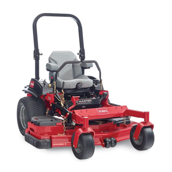
Toro Z Master Professional 5000 Series Operator's Manual
With 60in and 72in turbo force rear discharge mower
Hide thumbs
Also See for Z Master Professional 5000
Series:
- Operator's manual (92 pages) ,
- Setup instructions (16 pages) ,
- Operator's manual (68 pages)
Table of Contents
Advertisement
Advertisement
Table of Contents

Related Manuals for Toro Z Master Professional 5000 Series


Summary of Contents for Toro Z Master Professional 5000 Series
- Page 1 Z Master ® Professional 5000 Series Riding Mower with 60in and 72in TURBO FORCE ® Rear Discharge Mower Model No. 74942—Serial No. 315000001 and Up Model No. 74944—Serial No. 315000001 and Up *3400-941* B Register at www.Toro.com. Original Instructions (EN)
- Page 2 Whenever you need service, genuine Toro parts, or additional information, contact an Authorized Service Dealer or Toro Customer Service and have the model © 2018—The Toro® Company Contact us at www.Toro.com. 8111 Lyndale Avenue South...
-
Page 3: Table Of Contents
Checking the Seat Belt ........48 Safety ............... 4 Checking the Rollover-Protection System Safe Operating Practices........4 (ROPS) Knobs ..........48 Toro Mower Safety..........6 Adjusting the Tracking ........48 Slope Indicator ........... 7 Checking the Tire Pressure....... 49 Safety and Instructional Decals ......8 Checking the Wheel Lug Nuts...... -
Page 4: Safety
Manual. Modifications to this machine should only be made by either the manufacturer or an Authorized Operation Toro Dealer. • Lightning can cause severe injury or death. If This product is capable of amputating hands and feet. lightning is seen, or thunder is heard in the area, Follow all safety instructions to avoid serious injury do not operate the machine;... -
Page 5: Maintenance And Storage
Maintenance and Storage Make the necessary repairs before resuming operation. • Disengage drives, set the parking brake, shut off • Keep your hands and feet away from the cutting the engine, and remove the key or disconnect unit. spark-plug wire. Wait for all movement to stop before adjusting, cleaning, or repairing. -
Page 6: Toro Mower Safety
Do not store the machine or a fuel container inside The following list contains safety information specific where there is an open flame, such as near a to Toro products and other safety information that you water heater or furnace. must know. -
Page 7: Slope Indicator
Slope Indicator g011841 Figure 3 This page may be copied for personal use. 1. The maximum slope you can safely operate the machine on is 15 degrees. Use the slope chart to determine the degree of slope of hills before operating. Do not operate this machine on a slope greater than 15 degrees. Fold along the appropriate line to match the recommended slope. -
Page 8: Safety And Instructional Decals
Safety and Instructional Decals Safety decals and instructions are easily visible to the operator and are located near any area of potential danger. Replace any decal that is damaged or lost. decal99-8936 99-8936 1. Machine speed 4. Neutral 2. Fast 5. - Page 9 decal116-1716 116-1716 1. Fuel 6. Hour meter 2. Empty 7. PTO 3. Half 8. Parking brake decal109-6036 109-6036 4. Full 9. Neutral 5. Battery 10. Operator-presence switch 1. Read the Operator’s manual 2. Remove the ignition key and read the instructions before servicing or performing maintenance.
- Page 10 decaloemmarkt Manufacturer's Mark 1. Indicates the blade is identified as a part from the original machine manufacturer. decal116-5988 116-5988 1. Parking brake—engaged 2. Parking brake—disengaged decal117-0346 117-0346 1. Fuel leak hazard—read the Operator's Manual; do not attempt to remove the roll bar; do not weld, drill, or modify the roll bar in any way.
- Page 11 decal126-2055 126-2055 1. Wheel lug-nut torque 129 N∙m (95 ft-lb) (4x) 2. Wheel-hub nut torque 319 N∙m (235 ft-lb) 3. Read and understand the Operator’s manual before decal117-3864 performing any maintenance, check torque after first 100 117-3864 hours then every 500 hours thereafter. 1.
- Page 12 decal131-4036 131-4036 1. Maximum drawbar pull 36 2. Read the Operator's kg (80 lb) Manual. decal127-6663 127-6663 1. Warning—read the 2. Crushing hazard—1) Operator's Manual. Engage the parking brake, shut off the engine, and remove the key from the ignition; 2) Jack the machine using a manufacturer-approved jack, and always use a...
- Page 13 decal132-0871 132-0871 Note: This machine complies with the industry standard stability test in the static lateral and longitudinal tests with the maximum recommended slope indicated on the decal. Review the instructions for operating the machine on slopes in the Operator’s Manual as well as the conditions in which you would operate the machine to determine whether you can operate the machine in those conditions on that day and at that site.
-
Page 14: Product Overview
Product Overview g013112 Figure 5 1. PTO switch 4. Hour meter/Safety-interlock display/Fuel gauge 2. Throttle control 5. Ignition switch 3. Malfunction indicator light 6. Fuses (MIL) g027405 Figure 4 Hour Meter 1. Height-of-cut deck lift 6. Roll bar pedal The hour meter records the number of hours the 2. -
Page 15: Ignition Switch
A selection of Toro approved attachments and accessories is available for use with the machine to enhance and expand its capabilities. Contact your Authorized Service Dealer or Distributor or go to www.Toro.com for a list of all approved attachments and accessories. -
Page 16: Specifications
Specifications Operation Note: Specifications and design are subject to Note: Determine the left and right sides of the change without notice. machine from the normal operating position. Width: Adding Fuel 60 inch Mower 72 inch Mower Deck Deck • For best results, use only clean, fresh (less than Without Mower 134.6 cm (53.0 150.1 cm (59.1... -
Page 17: Filling The Fuel Tank
Add the correct amount of gasoline DANGER stabilizer/conditioner to the gasoline. In certain conditions during fueling, static Note: A fuel stabilizer/conditioner is most effective electricity can be released, causing a spark when mixed with fresh gasoline. that can ignite the gasoline vapors. A fire or explosion from gasoline can burn you and others and can damage property. -
Page 18: Checking The Engine-Oil Level
Using the Rollover Protection System (ROPS) WARNING To avoid injury or death from rollover: keep the roll bar in the fully raised locked position g024209 and use the seat belt. Ensure that the rear part of the seat is secured with the seat latch. -
Page 19: Think Safety First
Think Safety First Please read all safety instructions and symbols in the safety section. Knowing this information could help you or bystanders avoid injury. DANGER Operating the machine on wet grass or steep slopes can cause sliding and loss of control. •... -
Page 20: Operating The Parking Brake
Setting the Parking Brake WARNING The parking brake may not hold a machine parked on a slope and could cause personal injury or property damage. Do not park the machine on slopes unless the wheels are chocked or blocked. g000963 Figure 9 1. -
Page 21: Operating The Throttle
to start allow a 15 second cool-down period between attempts. Failure to follow these instructions can burn out the starter motor. Note: You may need multiple attempts to start the engine when you start it the first time after the fuel system has been without fuel completely. g008945 Figure 13 Disengaging the Blade-Control... -
Page 22: Using The Fuel-Shutoff Valve
Using the Fuel-Shutoff Valve The fuel-shutoff valve is located under the seat. Move the seat forward to access it. Close the fuel-shutoff valve for transport, maintenance, and storage. Ensure the fuel-shutoff valve is open when starting the engine. g008948 Figure 17 g032328 1. -
Page 23: Using The Safety-Interlock System
Using the Safety-Interlock System CAUTION If the safety-interlock switches are disconnected or damaged, the machine could operate unexpectedly, causing personal injury. • Do not tamper with the interlock switches. • Check the operation of the interlock switches daily and replace any damaged switches before operating the machine. -
Page 24: Driving Forward Or Backward
Testing the Safety-Interlock CAUTION System Machine can spin very rapidly. Operator may lose control of machine and cause personal Service Interval: Before each use or daily injury or damage the machine. Test the safety-interlock system before you use the • Use caution when making turns. machine each time. -
Page 25: Stopping The Machine
Stopping the Machine To stop the machine, move the traction control levers to N and then to the N position, EUTRAL EUTRAL LOCK disengage the blade-control switch (PTO), and turn the ignition key to the O position. Set the parking brake when you leave the machine; refer to Setting the Parking Brake (page 20). -
Page 26: Adjusting The Anti-Scalp Rollers
Push on the deck-lift pedal with your foot and raise the mower deck to the transport position (also the 140 mm (5-1/2 inch) cutting-height position) (Figure 25). To adjust, rotate the pin 90 degrees and remove the pin from the height-of-cut bracket (Figure 25). -
Page 27: Adjusting The Skid(S)
Disengage the blade-control switch (PTO) and set the parking brake. Move the throttle lever to the S position, shut off the engine, remove the key, and wait for all moving parts to stop before leaving the operating position. Remove the carriage bolts and nuts from each skid (Figure 28). -
Page 28: Unlatching The Seat
g019754 Figure 29 g019768 Figure 31 Unlatching the Seat 1. Seat-suspension knob Note: Certain models have a fixed seat and cannot be rotated up. Using the Drive-Wheel Release Valves WARNING Your hands may become entangled in the rotating drive components below the engine deck, which could result in serious injury. -
Page 29: Transporting The Machine
Transporting the Machine Use a heavy-duty trailer or truck to transport the machine. Ensure that the trailer or truck has all necessary brakes, lighting, and marking as required by law. Please carefully read all the safety instructions. Knowing this information could help you, your family, pets, or bystanders avoid injury. -
Page 30: Loading The Machine
Loading the Machine WARNING Loading a machine onto a trailer or truck Use extreme caution when loading or unloading the increases the possibility of a tip-over and machine onto a trailer or a truck. Use a full-width ramp could cause serious injury or death. that is wider than the machine for this procedure. - Page 31 g027996 Figure 35 1. Full-width ramp in stowed 4. The ramp is at least 4 position times as long as the height of the trailer or truck bed to the ground. 2. Side view of full-width 5. H= height of the trailer or ramp in loading position truck bed to the ground 3.
-
Page 32: Operating Tips
Alternate the mowing direction to keep the grass as necessary. If a blade is damaged or worn, replace standing straight. This also helps disperse clippings, it immediately with a genuine Toro replacement blade. which enhances decomposition and fertilization. Mowing at Correct Intervals Grass grows at different rates at different times. -
Page 33: Maintenance
• Adjust the caster-pivot bearing. Every 500 hours • Check the parking-brake adjustment. • Change the hydraulic filters and hydraulic fluid when using Toro® HYPR-OIL™ 500 hydraulic oil (more often in dirty or dusty conditions). • Replace the inner air filter. -
Page 34: Lubrication
CAUTION If you leave the key in the ignition switch, someone could accidently start the engine and seriously injure you or other bystanders. Remove the key from the ignition before you perform any maintenance. Lubrication Greasing the Mower Service Interval: Every 50 hours—Grease the mower Greasing and Lubrication deck spindles. -
Page 35: Lubricating The Caster Wheel Hubs
g027339 g024207 Figure 40 Figure 38 Grease the drive-belt idler arm (Figure 37). Lubricating the Caster Wheel Hubs Service Interval: Yearly Shut off the engine, wait for all moving parts to stop, remove the key and engage the parking brake. g009030 Figure 39 g006115... -
Page 36: Engine Maintenance
Engine Maintenance If the axle assembly has had both spacer nuts removed (or broken loose), apply a thread-locking adhesive to 1 spacer nut and thread onto the axle with the wrench flats facing WARNING outward. Do not thread spacer nut all of the way Contact with hot surfaces may cause personal onto the end of the axle. - Page 37 Important: Release the latches on the air cleaner and pull Never attempt to clean the safety the air-cleaner cover off the air cleaner body filter. If the safety filter is dirty, then the primary (Figure 43). filter is damaged. Replace both filters. Clean the inside of the air-cleaner cover with compressed air.
-
Page 38: Servicing The Engine Oil
Servicing the Engine Oil Oil Type: Detergent oil (API service class SJ or higher) Oil Capacity: with a filter change, 1.7 L (58 oz); with no filter change, 1.4 L (48 oz) g024213 Viscosity: See the table below. g012991 Figure 44 Note: Use of synthetic oil having 5W-20 or 5W-30 rating is acceptable, up to 4°C (40°F). - Page 39 Changing the Engine Oil Slowly pour approximately 80% of the specified oil into the filler tube and slowly add the Service Interval: Every 100 hours (more often in dirty additional oil to bring it to the F mark (Figure or dusty conditions). 47).
- Page 40 g024213 g024213 g013011 Figure 49 1. Engine-oil cooler 2. Bolts g027477 Figure 48 Note: Ensure the oil filter gasket touches the engine and then turn the oil filter an extra 3/4 turn. Fill the crankcase with the proper type of new oil;...
-
Page 41: Servicing The Spark Plug
Servicing the Spark Plug Service Interval: Every 200 hours—Check, clean and regap the spark plug. Make sure the air gap between the center and side electrodes is correct before installing the spark plug. Use a spark plug wrench for removing and installing g024214 the spark plug(s) and a gapping tool/feeler gauge to check and adjust the air gap. -
Page 42: Checking The Spark Arrester
Checking the Spark Plug Checking the Spark Arrester Important: Replace the spark plug(s) when it has: a black coating, worn electrodes, an oily film, cracks or reuse is questionable. For a model with a Spark Arrester If you see light brown or gray on the insulator, the Service Interval: Every 50 hours engine is operating properly. -
Page 43: Fuel System Maintenance
Fuel System Maintenance WARNING Fuel system components are under high pressure. The use of improper components can result in system failure, gasoline leakage and possible explosion. Use only approved fuel lines and fuel filters. Servicing the Electronic Fuel-Injection System g008963 Figure 54 This machine contains an electronic fuel-injection 1. -
Page 44: Electrical System Maintenance
Electrical System WARNING Incorrect battery cable routing could damage Maintenance the machine and cables causing sparks. Sparks can cause the battery gasses to explode, resulting in personal injury. Servicing the Battery • Always disconnect the negative (black) Service Interval: Monthly battery cable before disconnecting the positive (red) cable. -
Page 45: Charging The Battery
g000960 Figure 57 1. Positive battery post 3. Red (+) charger lead g032526 Figure 56 2. Negative battery post 4. Black (-) charger lead Charging the Battery WARNING Charging the battery produces gasses that can explode. Never smoke near the battery and keep sparks and flames away from battery. -
Page 46: Replacing The Fuses
Replacing the Fuses DANGER Jump starting a weak battery that is The electrical system is protected by fuses. It requires cracked, frozen, has low electrolyte level, no maintenance, however, if a fuse blows check the or an open/shorted battery cell, can component and circuit for a malfunction or short. - Page 47 Start the vehicle and remove the cables in the reverse order of connection (the engine block (black) connection is the first to disconnect). g012785 Figure 59 1. Positive (+) cable on 5. Booster battery discharged battery 2. Positive (+) cable on 6.
-
Page 48: Drive System Maintenance
Drive System Maintenance Checking the Seat Belt Service Interval: Before each use or daily Inspect the seat belt for wear, cuts, and proper operation of the retractor and buckle. Replace the seat belt if it is damaged. Checking the Rollover-Protection System (ROPS) Knobs Service Interval: Before each use or daily WARNING... -
Page 49: Checking The Tire Pressure
If it tracks to the left, loosen the bolts and adjust the right stop plate rearward on the right T-slot until the machine tracks are straight (Figure 63). Tighten the stop plate (Figure 63). g001055 Figure 64 Checking the Wheel Lug Nuts Service Interval: After the first 100 hours Every 500 hours... -
Page 50: Adjusting The Caster-Pivot Bearing
g001297 Figure 66 1. Spring washers 3. Dust cap 2. Locknut g027408 Figure 65 1. Slotted nut Using the Clutch Shim Some later model year units have been built with clutches that contain a brake shim. When the clutch Adjusting the Caster-Pivot brake has worn to the point where the clutch no longer engages consistently, you can remove the shim to Bearing... - Page 51 Engage the parking brake and wait for the machine to cool completely. Using an air compressor, blow out any debris from under the brake pole and around the brake spacers. g010871 Figure 70 1. Shim Using a pneumatic line, blow out any debris from under the brake pole and around the brake spacers.
-
Page 52: Cooling System Maintenance
Cooling System • If the gap is less than 0.010 inch, install the shim and refer to Troubleshooting Maintenance (page 71). • If the gap is sufficient, proceed to the safety check in step F. Cleaning the Engine Screen Perform the following safety check: and Engine-Oil Cooler Sit on the seat and start the engine. -
Page 53: Cleaning The Hydraulic Units
g024214 g004218 g009920 Figure 74 Figure 75 1. Engine guard 4. Fan housing 1. Hydraulic units 2. Engine air-intake screen 5. Screw 3. Bolt Cleaning the Hydraulic Units Service Interval: Before each use or daily Disengage the blade-control switch (PTO) and set the parking brake. -
Page 54: Brake Maintenance
Brake Maintenance Adjusting the Parking Brake Service Interval: After the first 100 hours Every 500 hours thereafter Check to make sure the brake is adjusted properly before adjusting. Drive the machine onto a level surface. Disengage the blade-control switch (PTO), move g026961 the motion-control levers to the N EUTRAL... -
Page 55: Belt Maintenance
Belt Maintenance Use a ratchet in the square hole in the idler arm to remove tension on the idler spring (Figure 77). Remove the belt from the mower deck pulley Inspecting the Belts (Figure 77). Remove the belt from the remaining pulleys Service Interval: Every 50 hours (Figure 77). -
Page 56: Replacing The Hydraulic-Pump Drive Belt
g027730 Figure 80 Replacing the Hydraulic-Pump Drive Belt g024146 Figure 79 Disengage the blade-control switch (PTO) and 5. Belt guide 1. Clutch pulley set the parking brake. 2. Mower belt 6. Spring-loaded idler pulley 3. Spring-loaded idler pulley 7. Square hole in the idler Shut off the engine, remove the key, and wait arm for the ratchet for all moving parts to stop before leaving the... -
Page 57: Controls System Maintenance
Controls System Maintenance Adjusting the Control Handle Position There are 2 height positions for the control levers—high and low. Remove the bolts to adjust the height for the operator. Disengage the blade-control switch (PTO), move the motion-control levers to the N EUTRAL LOCK position, and set the parking brake. -
Page 58: Adjusting The Motion-Control Linkage
Start the engine. g009195 Figure 83 Adjusting the Motion-Control Linkage The pump-control linkages are located on either side of the fuel tank, below the seat. Rotate the pump linkage with a 1/2 inch wrench for fine-tuning adjustments so that the machine does not move in the position. -
Page 59: Adjusting The Motion-Control Damper
Note: Engage the parking brake and move Raise the deck and install the height-of-cut pin. the motion-control levers out before starting Check that the machine does not creep in the engine. You do not need to be in the seat when you disengage the parking EUTRAL because of the jumper wire being used. -
Page 60: Hydraulic System Maintenance
Hydraulic System Tighten jam nut. Maintenance Servicing the Hydraulic System Hydraulic Fluid Type: Toro ® HYPR-OIL ™ hydraulic oil or Mobil ® 1 15W-50. g008621 Important: Use the hydraulic fluid specified. Figure 86 Other fluids could damage the hydraulic system. - Page 61 Mobil ® 1 oil (more often in dirty or dusty conditions). Every 500 hours—Change the hydraulic filters and hydraulic fluid when using Toro ® HYPR-OIL ™ 500 hydraulic oil (more often in dirty or dusty conditions).
-
Page 62: Mower Deck Maintenance
Mower Deck Maintenance Leveling the Mower Deck Setting up the Machine Note: Ensure the mower deck is level before matching the height of cut (HOC). Position mower on a flat surface. Disengage the blade-control switch (PTO), move the motion-control levers to the N EUTRAL LOCK position, and set the parking brake. - Page 63 g024245 Figure 91 g027343 1. 7.6 cm (3 inches) at 3. Measure here from the Figure 90 position A is correct. blade tip to the hard surface. 1. Deck-lift pedal 3. Transport lock 4. Measure at position A and 2. 8.3 cm (3-1/4 inches) at 2.
- Page 64 g027345 Figure 94 1. Bolts at the bottom of the height-of-cut plate g027410 Figure 92 If the deck is too low, tighten the single-point 1. Whizlock nut 3. Jam nut adjustment bolt by rotating it clockwise. If 2. Adjuster screw 4.
-
Page 65: Servicing The Cutting Blades
On both sides of the deck, measure from the level surface to the back tip of the blade (position B). Ensure the measurement is 8.3 cm (3-1/4 inches) (Figure 91). Fine-tune the screw adjuster by turning it to get 8.3 mm (3-1/4 inches) height (Figure 92). -
Page 66: Removing The Blades
2. Blade 4. Blade bolt the machine, use genuine Toro replacement blades. Replacement blades made by other manufacturers may result in nonconformance with safety standards. Hold the blade end using a rag or a thickly padded glove. - Page 67 Sharpening the Blades Use a file to sharpen the cutting edge at both ends of the blade (Figure 100). Note: Maintain the original angle. Note: The blade retains its balance if the same amount of material is removed from both cutting edges.
-
Page 68: Removing The Mower Deck
Removing the Mower Deck Before servicing or removing the mower deck, lock out the spring-loaded deck arms. WARNING Deck lift arm assemblies have stored energy. Removing the deck with out releasing the stored energy can cause serious injury or death. Do not attempt to disassemble the deck from the front frame without locking out the stored energy. -
Page 69: Cleaning
Cleaning Cleaning under the Mower Service Interval: Before each use or daily Disengage the blade-control switch (PTO), move the motion-control levers to the N EUTRAL LOCK position, and set the parking brake. Shut off the engine, remove the key, and wait for all moving parts to stop before leaving the operating position. -
Page 70: Storage
Storage Note: A fuel stabilizer/conditioner is most effective when mixed with fresh fuel and used at all times. Cleaning and Storage Run the engine to distribute conditioned fuel through the fuel system (5 minutes). Disengage the blade-control switch (PTO), set the parking brake, turn the ignition key to the Shut off the engine, allow it to cool, and position, and remove the key. -
Page 71: Troubleshooting
Troubleshooting Problem Possible Cause Corrective Action The starter does not crank. 1. The blade-control switch (PTO) is 1. Move the blade-control switch (PTO) engaged. to disengaged. 2. The parking brake is not on. 2. Set the parking brake. 3. The drive levers are not in 3. - Page 72 Problem Possible Cause Corrective Action The machine does not drive. 1. The by pass valves are not closed 1. Tighten the by pass valves. tight. 2. The pump belt is worn, loose or broken. 2. Change the belt. 3. The pump belt is off a pulley. 3.
- Page 73 Problem Possible Cause Corrective Action Malfunction Indicator Light (MIL) comes 1. The engine is too hot. 1. Turn the engine off and let it cool. 2. There is old gas in the gas tank. 2. Use new gas. 3. The fuel-shutoff valve is not open 3.
-
Page 74: Schematics
Schematics g013119 Wire Diagram (Rev. A) - Page 75 Notes:...
- Page 76 Customers who have purchased Toro products outside the United States or Canada should contact their Toro Distributor (Dealer) to obtain guarantee policies for your country, province, or state. If for any reason you are dissatisfied with your Distributor's service or have difficulty obtaining guarantee information, contact the Toro importer. If all other remedies fail, you may contact us at Toro Warranty Company.