Symbol MC9000-G Product Reference Manual
For embedded windows ce.net
Hide thumbs
Also See for MC9000-G:
- Product reference manual (646 pages) ,
- Quick start manual (2 pages) ,
- Product reference manual (392 pages)
Table of Contents
Advertisement
Quick Links
Advertisement
Table of Contents

Related Manuals for Symbol MC9000-G


Summary of Contents for Symbol MC9000-G
- Page 1 MC9000-G Product Reference Guide ® for Embedded Windows CE .NET...
- Page 3 ® MC9000-G for Embedded Windows CE .NET Product Reference Guide 72E-54436-08 Revision A March 2006...
- Page 4 Symbol does not assume any product liability arising out of, or in connection with, the application or use of any product, circuit, or application described herein. No license is granted, either expressly or by implication, estoppel, or otherwise under any Symbol Technologies, Inc., intellectual property rights. An implied license only exists for equipment, circuits, and subsystems contained in Symbol products.
-
Page 5: Revision History
Revision History Changes to the previous manual are listed below: Change Date -02 to -03 1/15/04 -03 to -04 6/18/04 -04 to -05 9/13/04 -05 to -06 12/06/04 -06 to -07 6/06/05 -07 to -08 3/06/06 Updated Operating system to Win CE 4.2. Added new screens and menus, Chapter 2 and Chapter 3. -
Page 7: Table Of Contents
Contents Revision History ............iii Chapter. - Page 8 MC9000-G for Embedded Windows® CE .NET Product Reference Guide Main Battery Insertion and Removal ........1-8 Insert the Main Battery .
- Page 9 RFID (MC9000-G RFID Only) ........
- Page 10 MC9000-G for Embedded Windows® CE .NET Product Reference Guide Chapter 3. Settings Introduction............3-5 Windows Control Panel Menu .
- Page 11 System ............3-35 General Tab .
- Page 12 MC9000-G for Embedded Windows® CE .NET Product Reference Guide Chapter 4. Communications Introduction............4-3 Installing Communication Software .
- Page 13 AudioSamp ............5-13 Images .
- Page 14 MC9000-G for Embedded Windows® CE .NET Product Reference Guide Chapter 6. Spectrum24 Network Configuration Introduction............6-3 Mobile Companion .
- Page 15 Four Slot Ethernet Cradle ..........7-12 Setup.
- Page 16 MC9000-G for Embedded Windows® CE .NET Product Reference Guide Chapter 8. Software Installation Introduction............8-3 SMDK for C .
- Page 17 Chapter 11. Mobile Computer Configuration Introduction............11-3 Starting Terminal Configuration Manager .
- Page 18 MC9000-G for Embedded Windows® CE .NET Product Reference Guide Chapter 12. Desktop Emulator Introduction............12-3 Software Requirements .
- Page 19 Chapter 13. Maintenance and Troubleshooting Introduction............13-3 Maintaining the Mobile Computer .
- Page 20 MC9000-G for Embedded Windows® CE .NET Product Reference Guide...
-
Page 21: About This Guide
About This Guide Chapter Contents Introduction............... . xxi Chapter Descriptions . - Page 22 MC9000-G Product Reference Guide for Embedded Windows® CE .NET...
-
Page 23: Introduction
Introduction The MC9000-G Product Reference Guide provides information about the MC9000-G mobile computer ® using the Embedded Windows includes the following variations: ® • MC9010-G: Windows with integrated laser scanner, or 1-dimensional and 2-dimensional bar code scanning with integrated imager; 802.11 Spectrum24 network (WLAN) communication;... -
Page 24: Chapter Descriptions
MC9000-G Product Reference Guide for Embedded Windows® CE .NET Chapter Descriptions Topics covered in this guide are as follows: • Chapter 1, Getting Started mobile computer accessories, explains how to install and charge the batteries, explains how to replace the strap lanyard, explains how to remove and replace the stylus and explains how to start the mobile computer for the first time. -
Page 25: Notational Conventions
The following conventions are used in this document: • “Mobile computer” refers to any Symbol terminal. • MC9000-G Series refers to all configurations of the MC9000-G with the exception of MC9000-G RFID configurations. • “User” refers to anyone using an application on the terminal. -
Page 26: Related Documents And Software
MC9000-G Product Reference Guide for Embedded Windows® CE .NET Related Documents and Software The following documents provide more information about the MC9000-G. • MC9000-G Quick Start Guide (poster), p/n 72-63360-xx • MC9000-G Licensing, Patent and Regulatory Information, p/n 72-63697-xx •... -
Page 27: Symbol Support Center
Symbol Place Winnersh Triangle, Berkshire RG41 5TP United Kingdom 0800 328 2424 (Inside UK) +44 118 945 7529 (Outside UK) Australia Symbol Technologies Pty. Ltd. 432 St. Kilda Road Melbourne, Victoria 3004 1-800-672-906 (Inside Australia) +61-3-9866-6044 (Outside Australia) Denmark/Danmark Symbol Technologies AS Dr. - Page 28 MC9000-G Product Reference Guide for Embedded Windows® CE .NET Germany/Deutschland Symbol Technologies GmbH Waldstrasse 66 D-63128 Dietzenbach, Germany 6074-49020 (Inside Germany) +49-6074-49020 (Outside Germany) Latin America Sales Support Latin America & The Caribbean 2730 University Drive Coral Springs, Florida 33065 United States +1.954.255.2610 (Outside US)
- Page 29 Sweden/Sverige “Letter” address: Symbol Technologies AB Box 1354 S-171 26 SOLNA Sweden Visit/shipping address: Symbol Technologies AB Solna Strandväg 78 S-171 54 SOLNA Sweden Switchboard: 08 445 29 00 (domestic) Call Center: +46 8 445 29 29 (international) Support E-Mail: Sweden.Support@se.symbol.com If the Symbol product was purchased from a Symbol Business Partner, contact that Business Partner for service.
- Page 30 MC9000-G Product Reference Guide for Embedded Windows® CE .NET...
- Page 31 Chapter Contents Introduction............... . . 1-3 Unpacking .
- Page 32 MC9000-G Product Reference Guide for Embedded Windows® CE .NET Starting the Mobile Computer ............. 1-15 Calibration Screen .
-
Page 33: Chapter 1. Getting Started
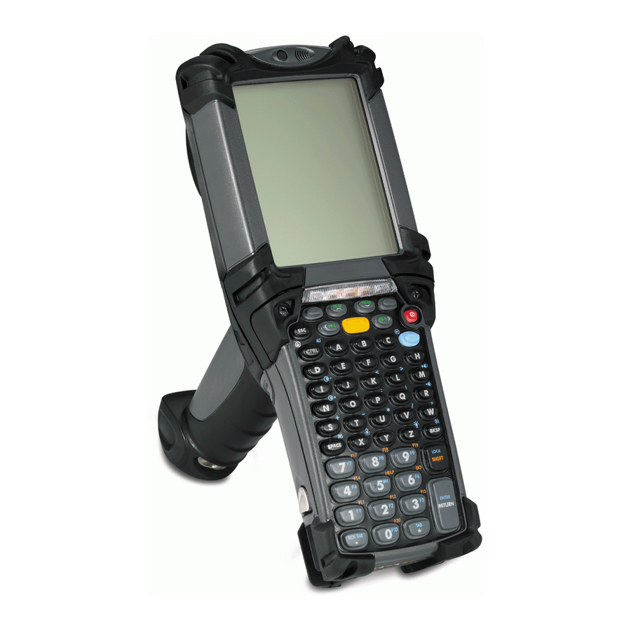
Indicator LED Bar Keypad Strap Lanyard Figure 1-1. MC9000-G: Mobile Computer Touch Screen Stylus Getting Started Microphone (optional) Exit Window Headphone... - Page 34 MC9000-G Product Reference Guide for Embedded Windows® CE .NET RFID Antenna Figure 1-2. MC9000-G RFID...
-
Page 35: Unpacking
Carefully remove all protective material from around the mobile computer and save the shipping container for storage and/or re-shipping. Verify that all of the equipment listed below was received: • MC9000-G mobile computer • Main lithium-ion battery • Strap lanyard, attached to the mobile computer •... -
Page 36: Accessories
MC9000-G Product Reference Guide for Embedded Windows® CE .NET Accessories • Single Slot Serial/USB Cradle, charges the mobile computer main battery and a spare battery. It also synchronizes the mobile computer with a host computer through a serial or a USB connection. -
Page 37: Smdk For C And Sdk
SMDK for C and SDK Symbol offers two development kits for the MC9000-G: • Symbol Mobility Developer Kit for .NET (SMDK for .NET), available at: http://www.symbol.com/mc9000-g • Symbol Mobility Developer Kit for C (SMDK for C), available at: http://www.symbol.com/mc9000-g The SMDK for C allows users to develop Windows CE applications for Series 9000 mobile computers. -
Page 38: Main Battery Insertion And Removal
MC9000-G Product Reference Guide for Embedded Windows® CE .NET Main Battery Insertion and Removal Insert the main battery into the mobile computer before use. If the main battery is charged the mobile computer can be used immediately. If the main battery is not charged see 1-10. -
Page 39: Main Battery Removal
Main Battery Removal To remove the main battery: 1. Prior to removing the battery, press the red Power button to turn off the screen. This sets the mobile computer to suspend mode. 2. Simultaneously press both primary battery releases. The battery partially ejects from the mobile computer. -
Page 40: Battery Charging
1-10 MC9000-G Product Reference Guide for Embedded Windows® CE .NET Battery Charging The mobile computer’s cradles, snap-ons and spare battery chargers can be used to charge the mobile computer’s main battery. Before using the mobile computer for the first time, fully charge the main battery (until the charge... -
Page 41: Mobile Computer Charging Procedures
• Chargers: The mobile computer’s spare battery charging accessories are used to charge batteries that are removed from the mobile computer. For detailed spare battery charging accessories setup and charging procedures see: • Single Slot Serial/USB Cradle on • Four Slot Spare Battery Charger on •... -
Page 42: Spare Battery Charging
1-12 MC9000-G Product Reference Guide for Embedded Windows® CE .NET Spare Battery Charging The mobile computer has three accessories that can be used to charge spare batteries. • Single Slot Serial/USB Cradle • Four Slot Spare Battery Charger • UBC Adapter. -
Page 43: Stylus
1-13 Getting Started Stylus Use the mobile computer stylus for selecting items and entering information. The stylus functions as a mouse. Tap the touch screen once with the stylus to select options and open menu items. To remove the stylus, pull the stylus cord down and outward to remove the stylus. Figure 1-5. -
Page 44: Strap Lanyard
1-14 MC9000-G Product Reference Guide for Embedded Windows® CE .NET Strap Lanyard The strap lanyard may be moved to either the left or right side of the mobile computer to suite user preferences. To reposition the strap lanyard: 1. Disconnect the strap lanyard disconnect clip. -
Page 45: Starting The Mobile Computer
1-15 Getting Started Starting the Mobile Computer Insert the battery, if the mobile computer does not power on perform a cold boot, see Resetting the Mobile Computer on page 2-41. When the mobile computer is powered on for the first time, it initializes its flash file system. The Symbol splash screen appears for a short period of time, followed by the calibration screen. -
Page 46: Calibration Screen
1-16 MC9000-G Product Reference Guide for Embedded Windows® CE .NET Calibration Screen Use calibrate screen to align the touch screen: 1. Remove the stylus from the handle. 2. Carefully press and briefly hold the tip of stylus on the center of the calibration screen target. -
Page 47: Mobile Computer Configuration
Mobile Computer Configuration The following chapters provide the mobile computer configuration information: • To customize the mobile computer settings, see • To set up ActiveSync to synchronize the mobile computer and accessories with the host computer, see Chapter 4, • To configure the mobile computer for Spectrum24, see Configuration. - Page 48 1-18 MC9000-G Product Reference Guide for Embedded Windows® CE .NET...
- Page 49 Start Button ..............2-28 Operating the MC9000-G...
- Page 50 RFID (MC9000-G RFID Only) ........
-
Page 51: Introduction
For detailed keypad configurations including ASCII values and VK codes, see B, Keypad Maps. For information about using the soft keyboard input panel, see Using the Keyboard Input Panel on page for installation and removal procedures. 2-33. Operating the MC9000-G Appendix Entering Information... -
Page 52: 28-Key Keypad
MC9000-G Product Reference Guide for Embedded Windows® CE .NET 28-Key Keypad The 28-key keypad contains a Power button, application keys, scroll keys and a function key. The keypad is color-coded to indicate the alternate function key (blue) values and the alternate ALPHA key (orange) values. - Page 53 SHIFT key and then press the 4 key once to produce the letter ‘G’; press and release the ALPHA key, press and hold the SHIFT key and then press the 4 key three times to produce the letter ‘I’. Operating the MC9000-G Description Resetting the Mobile Computer on page Appendix B, Keypad Maps for mapping details.
- Page 54 MC9000-G Product Reference Guide for Embedded Windows® CE .NET Table 2-1. 28-Key Keypad Descriptions (Continued) Function (blue) Press and release the blue function key to activate the keypad alternate functions (shown on the keypad in blue). The keypad LED lights and the taskbar, see return to the normal keypad functions.
-
Page 55: 43-Key Keypad
Operating the MC9000-G 43-Key Keypad The 43-key keypad contains a Power button, application keys, scroll keys and a function key. The keypad is color-coded to indicate the alternate function key (blue) values and the alternate ALPHA key (orange) values. Note that keypad functions can be changed by an application so the mobile computer’s keypad may not function exactly as described. - Page 56 MC9000-G Product Reference Guide for Embedded Windows® CE .NET Power (red) Powers the mobile computer on and off. Used to reset the mobile computer, see Green/Red Dot Unassigned application function key. See Scan (yellow) Scan key - used for scanning applications, this key has the same function as pulling the trigger.
- Page 57 Produces an asterisk and the alphabetic character Z when the ALPHA function key is activated. Enter Executes a selected item or function. For detailed keypad configurations including ASCII values and VK codes, see Appendix B, Keypad Maps. Operating the MC9000-G Description...
-
Page 58: 53-Key Keypad
2-10 MC9000-G Product Reference Guide for Embedded Windows® CE .NET 53-Key Keypad There are two physical configurations of the 53-key keypad, however both of the keypads are functionally identical. The 53-key keypads contain a Power button, application keys, scroll keys and function keys. - Page 59 Description Resetting the Mobile Computer 2-41. Appendix B, Keypad Maps icon appears on the taskbar, see Table 2-9 on page 2-11 Operating the MC9000-G 2-26. Press and...
- Page 60 2-12 MC9000-G Product Reference Guide for Embedded Windows® CE .NET Table 2-3. 53-Key Descriptions (Continued) Control Shift Period/Decimal Point Star Enter For detailed keypad configurations including ASCII values and VK codes, see Appendix B, Keypad Description Press and release the CTRL key to activate the keypad alternate CTRL functions.
-
Page 61: 3270 Emulator
3270 emulation software. When the mobile computer is not running the 3270 emulation software, the 3270 keypad functions are the same as a 53- key keypad. Table 2-4 on page 2-14 for key and button descriptions and 2-13 Operating the MC9000-G... - Page 62 2-14 MC9000-G Product Reference Guide for Embedded Windows® CE .NET Power (red) Green/Red Dot Scan (yellow) Scroll Up and Down Scroll Left and Right Alpha SPACE/BKSP Application Function (blue) Table 2-4. 3270 Emulator Descriptions Powers the mobile computer on and off.
- Page 63 Enter Executes a selected item or function. For detailed keypad configurations including ASCII values and VK codes, see Appendix B, Keypad Maps. Operating the MC9000-G Description icon appears on the icon appears on the taskbar. Press and release the 2-15...
-
Page 64: 5250 Emulator
2-16 MC9000-G Product Reference Guide for Embedded Windows® CE .NET 5250 Emulator There are two physical configurations of the 5250 emulator keypad, however both of the keypads are functionally identical. The 5250 emulator keypad contains a Power button, application keys, scroll keys and a function key. - Page 65 Description Resetting the Mobile Computer on 2-41. Appendix B, Keypad Maps icon appears on the taskbar, see Table 2-9 on page 2-17 Operating the MC9000-G 2-26. Press and...
- Page 66 2-18 MC9000-G Product Reference Guide for Embedded Windows® CE .NET Table 2-5. 5250 Emulator Descriptions (Continued) Control Shift Period/Decimal Point Star Enter For detailed keypad configurations including ASCII values and VK codes, see Appendix B, Keypad Description Press and release the CTRL key to activate the keypad alternate CTRL functions.
-
Page 67: Vt Emulator
VT emulation software. When the mobile computer is not running the VT emulation software, the VT keypad functions are the same as a 53-key keypad. Table 2-6 on page 2-20 for key and button descriptions and 2-19 Operating the MC9000-G Table... - Page 68 2-20 MC9000-G Product Reference Guide for Embedded Windows® CE .NET Power (red) Green/Red Dot Scan (yellow) Scroll Up and Down Scroll Left and Right Alpha SPACE/BKSP Application Function (blue) Table 2-6. VT Emulator Descriptions Description Powers the mobile computer on and off.
- Page 69 Enter Executes a selected item or function. For detailed keypad configurations including ASCII values and VK codes, see Appendix B, Keypad Maps. Operating the MC9000-G Description icon appears on the icon appears on the taskbar. Press and release the 2-21...
-
Page 70: Keypad Special Functions
2-22 MC9000-G Product Reference Guide for Embedded Windows® CE .NET Keypad Special Functions The keypad special functions are color coded on the keypads. For example, on the 53-key keypad, the display backlight icon is blue indicating that the blue function key must be selected first to access the display backlight. -
Page 71: Power Button
When a headset is plugged into the jack, the speaker is muted. 1-15. Chapter 4, Communications Resetting the Mobile Computer on page Figure 1-1 on page 1-3. Set the mobile computer volume 2-23 Operating the MC9000-G for detailed... -
Page 72: Series 9000 Demo Window
2-24 MC9000-G Product Reference Guide for Embedded Windows® CE .NET Series 9000 Demo Window On initial power up (or on a warm or cold boot) the Series 9000 Demo window appears. The Series 9000 Demo window icon functions are provided in Figure 2-7. - Page 73 Settings (1 and 2 MB Radios) on page Provides information about the OTL application, see The Series 9000 Demo window is the factory default launcher menu. Application specific shells may vary. Operating the MC9000-G Description Control Panel on page 3-40.
-
Page 74: Taskbar
2-26 MC9000-G Product Reference Guide for Embedded Windows® CE .NET Taskbar The taskbar (at the bottom of the window) displays the Start button, active programs (in this case PC Link and Mobile Companion), battery status and the communication status. The default taskbar icons... - Page 75 2-27 Operating the MC9000-G Table 2-10. Taskbar Buttons Icon Description The Start button. Tap to display the Start menu. The Keyboard Input Panel, display button. Tap to display the Keyboard Input Panel. The Keyboard Input Panel hide button. Tap to hide the Keyboard Input Panel.
-
Page 76: Start Button
2-28 MC9000-G Product Reference Guide for Embedded Windows® CE .NET Start Button Tap the Start button to launch the Start Menu or tap the Start button while in the ALT state and the Task Manager, Properties menu appears, see • Programs: Use to access available programs •... -
Page 77: Taskbar Icons
The amber LED in the mobile computer indicator LED bar, see page 1-3, also indicates low battery status and/or incorrect battery insertion. Table 2-9 on page 2-26. Battery status can also be viewed on the battery 3-45. 2-29 Operating the MC9000-G 2-26. Figure 1-1 on... -
Page 78: Task Manager And Properties
2-30 MC9000-G Product Reference Guide for Embedded Windows® CE .NET Task Manager and Properties Use the Task Manager to control an application’s use and use the Properties functions to set display and clock options. Task Manager 1. Select Function - CTRL, (to activate the ALT state) and tap the Start button to display the Task Manager, Properties Selection menu. -
Page 79: Properties
• Check the Show Clock checkbox to display the clock on the taskbar. 4. Tap OK to save the settings and exit the window. Figure 2-12. Taskbar and Start Menu, General Tab Operating the MC9000-G Figure 2-10 on page 2-30. - Page 80 2-32 MC9000-G Product Reference Guide for Embedded Windows® CE .NET Advanced Tab 1. Tap the Advanced tab to enter the Taskbar and Start Menu, Advanced Tab. 2. Tap the Clear button to delete all of the documents listed in the Start - Documents entry, Start Button on page list the Clear button would delete them.
-
Page 81: Entering Information
® to synchronize or copy information from the host computer to Keypads on page 2-3 for keypad configurations and see icon. Tap on a key to enter the key’s for the SMDK installation. 2-33 Operating the MC9000-G Chapter 4, Communications... -
Page 82: Data Capture
(including RSS) and two dimensional bar codes (including PDF417 and DataMatrix), and capture and download images to a host for a variety of imaging applications. Mobile computers with RFID technology (MC9000-G) allow data collection by decoding in-range RFID tags that beam back to the mobile computer the information they contain. -
Page 83: Indicator Led Bar
Contact the Symbol Support Center if chronic scanning difficulties develop. Decoding of properly printed bar codes should be quick and effortless. Table 2-11. Scan LED Indicators Indication Not scanning. Laser enabled, scanning in process. Successful decode. 2-35 Operating the MC9000-G Figure 1-1 on page 1-3. -
Page 84: Imaging
2-36 MC9000-G Product Reference Guide for Embedded Windows® CE .NET Imaging The imager version of the mobile computer has the following features: • Omnidirectional reading of a variety of bar code symbologies, including the most popular linear, postal, PDF417 and 2-D matrix code types. -
Page 85: Image Capture Mode
2-37 Operating the MC9000-G Image Capture Mode In this default mode, upon pulling the trigger, the Imager attempts to locate and decode enabled bar codes within its field of view. The Imager remains in this mode as long as the trigger is pulled, or until a bar code is decoded. -
Page 86: Scanning Tips
2-38 MC9000-G Product Reference Guide for Embedded Windows® CE .NET The imager can also read a bar code presented within the aiming pattern but not centered, such as the figure below on the left. The figure on the right, however, can not be decoded. -
Page 87: Rfid (Mc9000-G Rfid Only)
The mobile computer captures data from each new tag found. When the trigger is released, the mobile computer stops interrogating tags. In addition, RFID tag data can be stored on the mobile computer. Using the MC9000-G RFID sample application, tags that are read display in the main RFID Tags window, see... -
Page 88: Scan Led Indicator
2-40 MC9000-G Product Reference Guide for Embedded Windows® CE .NET 3. Position the mobile computer horizontally or vertically (as shown in on the orientation of the tag. 4. Pull the trigger. 5. An audible beep sounds, by default, and the Indicator LED bar flashes green one time to indicate the tag was decoded successfully. -
Page 89: Resetting The Mobile Computer
2-41 Operating the MC9000-G Resetting the Mobile Computer If the mobile computer stops responding to input, reset it. There are two reset functions, warm boot and cold boot. A warm boot restarts the mobile computer by closing all running programs. All data that is not saved is lost. -
Page 90: Performing A Cold Boot
2-42 MC9000-G Product Reference Guide for Embedded Windows® CE .NET Performing a Cold Boot A cold boot restarts the mobile computer and erases all user stored records and entries from RAM. Never perform a cold boot unless a warm boot does not solve the problem. -
Page 91: Waking The Mobile Computer
1. Power button is pressed. 2. AC power added or removed. Trigger Trigger is pressed. WLAN Wireless LAN accesses the mobile computer. Clock Real Time Clock set to sleep. Operating the MC9000-G for the SMDK installation. Table Conditions for wakeup 2-43... -
Page 92: File System Directory Structure
2-44 MC9000-G Product Reference Guide for Embedded Windows® CE .NET File System Directory Structure The mobile computer directory structure displays all of the file folders, see installed folders are in flash file system memory and optional removable storage devices (MMC storage cards). -
Page 93: Flash Storage
.wav file to play. This .wav file replaces the sound normally produced when running a .wav file with other actions (such as LED flashing, etc.). This feature allows applications that play .wav files to be portable between two devices, one that supports real audio and one that supports audio aliasing. 2-45 Operating the MC9000-G... -
Page 94: Terminal Emulators
2-46 MC9000-G Product Reference Guide for Embedded Windows® CE .NET Terminal Emulators Use the Terminal Emulator icon to enter the Wavelink terminal emulator application. From the Series 9000 Demo window, double-tap the Terminal Emulators icon. The Terminal Emulator window appears. - Page 95 Chapter Contents Introduction............... . . 3-5 Windows Control Panel Menu .
- Page 96 MC9000-G Product Reference Guide for Embedded Windows® CE .NET Mouse............... .3-24 Network and Dial-up Connections .
- Page 97 Audio Settings ..............3-57 Scanner Settings .
- Page 98 MC9000-G Product Reference Guide for Embedded Windows® CE .NET...
-
Page 99: Introduction
Settings Introduction This chapter provides basic instructions for customizing the mobile computer by adjusting settings. The system settings are accessed from the Windows CE Control Panel menu (see Table 3-1 on page 3-6), the Series 9000 Demo menu (see Table 3-4 on page 3-39) and the Control Panel menu (see Table 3-5 on page... - Page 100 MC9000-G Product Reference Guide for Embedded Windows® CE .NET Table 3-1. Windows Control Panel Menu Icons Icon Scan for, and setup Bluetooth compatible hardware, see for more information. View and modify digital certificates which are used by some applications for establishing trust for...
- Page 101 Table 3-1. Windows Control Panel Menu Icons (Continued) Icon Adjust double-click sensitivity for both the speed and timing. Connect to other computers, networks, and the Internet through a modem, see 3-15 for more information. Change owner's personal profiles, see Change settings for connectivity of a host computer, see information.
-
Page 102: Bluetooth Device Properties
MC9000-G Product Reference Guide for Embedded Windows® CE .NET Bluetooth Device Properties Use the Bluetooth Manager window to discover and create bonds with other Bluetooth devices. The mobile computer can receive information from discovered devices, without creating a bond. However, the exchange of information between the mobile computer and a bonded device occurs automatically when the Bluetooth radio is turned on. - Page 103 Settings 2. Scroll down the Power Settings window and double tap wlp1: Wireless LAN. 3. Double tap D4 in the S24 Power Selection window. This setting turns off the S24 radio. S24 Power Settings S24 Power Selection Figure 3-3. S24 Power Settings...
- Page 104 3-10 MC9000-G Product Reference Guide for Embedded Windows® CE .NET 4. Scroll up the Power Settings window and double tap com3: Bluetooth serial. 5. Double tap D0 in the Bluetooth Power Selection window. This turns on the Bluetooth radio. Power Settings Bluetooth Power Selection Figure 3-4.
-
Page 105: Starting Bluetooth
Starting Bluetooth 1. Select Start - Settings - Control Panel, and double-tap the Bluetooth Device Properties icon. Figure 3-5. Bluetooth Manager Window 2. Tap the Scan Device button to initiate a scan for Bluetooth hardware. The Bluetooth manager lists the Bluetooth devices that it finds, see found the Bluetooth Error window appears, see Icons. - Page 106 3-12 MC9000-G Product Reference Guide for Embedded Windows® CE .NET If the device to which the mobile computer is bonding does not appear in the list, ensure it is turned on, in discoverable mode, and within range (30 feet/ 10 meters) of the mobile computer.
- Page 107 3. Double tap the device to connect to on the device list. The Bluetooth Manager Authentication window appears. Tap No to connect to the device without authentication, or tap Yes to authenticate the device before connecting. Figure 3-8. Bluetooth Manager Authentication Window 4.
- Page 108 3-14 MC9000-G Product Reference Guide for Embedded Windows® CE .NET 5. When prompted, the same PIN must be entered on the other device. When the PIN is entered correctly on the other device, the bonded icon appears on the device list.
-
Page 109: Certificates
Certificates Certificates are used by some applications for establishing trust and for secure communications. Certificates are signed and issued by certificate authorities and are valid for a prescribed period of time. Windows CE manages multiple certificate stores. 1. Select Start - Settings - Control Panel, and double-tap the Certificates icon. Figure 3-11. -
Page 110: Date/Time
3-16 MC9000-G Product Reference Guide for Embedded Windows® CE .NET Date/Time Use the Date/Time Properties window to change the date, time and time zone information. 1. Select Start - Settings - Control Panel, and double-tap the Date/Time icon. Figure 3-12. Date/Time Properties Window 2. -
Page 111: Device Management
Device Management Use Device Management to keep track of software and hardware, inventory, and configure devices remotely. The device management client contains a download/install engine that allows users to receive software and notifications when there are new applications or Operating System (OS) updates. The device management system also allows the downloading and running of scripts to enable configuration and customized management. -
Page 112: Dialing
3-18 MC9000-G Product Reference Guide for Embedded Windows® CE .NET Dialing Use the Dialing Properties window to set dialing properties for modem communication and change telephony settings. 1. Select Start - Settings - Control Panel, and double-tap the Dialing icon. - Page 113 7. To edit the dialing properties select the location from the Location: drop-down list, and tap Edit. The Edit Dialing Patterns window appears. 8. Use the codes listed in Table window. Tap OK to save the new entries or tap X to exit without saving the new entries. Figure 3-16.
-
Page 114: Display
3-20 MC9000-G Product Reference Guide for Embedded Windows® CE .NET Display Use the Display Properties window to change desktop background image and the display appearance. Background Tab To select the background image: 1. Select Start - Settings - Control Panel, and double-tap the Display icon, tap the Background tab. -
Page 115: Appearance Tab
Appearance Tab To change the color scheme: 1. Select Start - Settings - Control Panel, and double-tap the Display icon, tap the Appearance tab. Figure 3-18. Display Properties - Appearance Tab 2. From the Scheme: drop-down list, select a scheme. 3. -
Page 116: Input Panel
3-22 MC9000-G Product Reference Guide for Embedded Windows® CE .NET Input Panel Use the Input Panel Properties window to switch input methods and to set the input options. 1. Select Start - Settings - Control Panel, and double-tap the Input Panel icon. -
Page 117: Keyboard
Keyboard Use the Keyboard Properties window to change the keyboard repeat rate and repeat delay. 1. Select Start - Settings - Control Panel, and double-tap the Keyboard icon. Figure 3-21. Keyboard Properties - Repeat Tab 2. Tap the Enable character repeat check box. 3. -
Page 118: Mouse
3-24 MC9000-G Product Reference Guide for Embedded Windows® CE .NET Mouse Use the Mouse Properties window to adjust stylus double-tap timing. 1. Select Start - Settings - Control Panel, and double-tap the Mouse icon. Figure 3-22. Mouse Properties Window 2. Double-tap the checkerboard grid at a comfortable speed. -
Page 119: Network And Dial-Up Connections
Network and Dial-up Connections Use the Connection window to set connections to other computers, networks, and the Internet. 1. Select Start - Settings - Control Panel, and double-tap the Network and Dial-up Connections icon. Figure 3-23. Connection Window 2. Double an icon to select a connection type. 3. -
Page 120: Owner
3-26 MC9000-G Product Reference Guide for Embedded Windows® CE .NET Owner Use the Owner Properties window to enter the owner information. The information can be displayed when the mobile computer is turned on. To enter information: Identification Tab 1. Select Start - Settings - Control Panel, and double-tap the Owner icon. -
Page 121: Notes Tab
Notes Tab 1. Select the Notes tab and enter information in the Notes box to add more information. 2. Select the Display owner notes box to include this information on the startup display. Figure 3-25. Owner Properties Window - Notes Tab Network ID Tab To setup identification for remote networks, select the Network ID tab and enter the user name, password, and domain name used to log on to the remote network. -
Page 122: Pc Connection
3-28 MC9000-G Product Reference Guide for Embedded Windows® CE .NET PC Connection Use the PC Connection Properties window to set the mobile computer communication baud rate (with the host computer). 1. Select Start - Settings - Control Panel, and double-tap the PC Connection icon. -
Page 123: Regional Settings
Regional Settings Use the Regional Settings, to set the way the mobile computer displays dates, times, currency amounts, large numbers, and numbers with decimal fractions. The system of measurement can also be set to either metric or U.S. Region Tab The selectable input locales are listed in the Your local: drop-down list. -
Page 124: Number Tab
3-30 MC9000-G Product Reference Guide for Embedded Windows® CE .NET Number Tab 1. Select the Number tab. Figure 3-30. Regional Settings Properties - Number Tab 2. Select desired options. The available options are determined by the Your local: selection and by the User Interface Language selection (on the Region tab). -
Page 125: Time Tab
Time Tab 1. Select the Time tab. Figure 3-32. Regional Settings Properties - Time Tab 2. Select desired options. The available options are determined by the Your local: selection and by the User Interface Language selection (on the Region tab). Date Tab 1. -
Page 126: Remove Programs
3-32 MC9000-G Product Reference Guide for Embedded Windows® CE .NET Remove Programs Use the Remove Programs window to remove user installed programs from the mobile computer: 1. Select Start - Settings - Control Panel, and double-tap the Remove Programs icon. -
Page 127: Stylus
Stylus Use the Stylus Properties window Double-Tap to adjust double-tap timing and use the Calibrate tab to recalibrate the touch screen. Double-Tap Tab 1. Select Start - Settings - Control Panel, and double-tap the Stylus icon. Figure 3-35. Stylus Properties - Double-Tap Tab 2. -
Page 128: Calibrate Tab
3-34 MC9000-G Product Reference Guide for Embedded Windows® CE .NET Calibrate Tab 1. Select Start - Settings - Control Panel, and double-tap the Stylus icon. Figure 3-36. Stylus Properties - Calibration Tab 2. Select the Calibration tab. 3. In the Calibration tab, tap Recalibrate. -
Page 129: System
System Use the System Properties window to view general system properties, change memory settings, input device name and view copyright information. General Tab The General tab view displays general system settings: 1. Select Start - Settings - Control Panel, and double-tap the System icon. 2. -
Page 130: Memory Tab
3-36 MC9000-G Product Reference Guide for Embedded Windows® CE .NET Memory Tab Use the Memory tab to adjust the RAM allocation. 1. Select Start - Settings - Control Panel, and double-tap the System icon. 2. Select the Memory tab. 3. To adjust RAM allocation move the slider to allocate more memory for programs or storage. -
Page 131: Device Name Tab
Device Name Tab Use the Device Name tab to customize the device name and description. 1. Select Start - Settings - Control Panel, and double-tap the System icon. 2. Select the Device Name tab. Figure 3-39. System Properties - Device Name Tab 3. -
Page 132: Copyrights Tab
3-38 MC9000-G Product Reference Guide for Embedded Windows® CE .NET Copyrights Tab The Copyrights tab displays relevant copyright information. 1. Select Start - Settings - Control Panel, and double-tap the System icon. 2. Tap the Copyrights tab to view the copyrights statement. -
Page 133: Series 9000 Demo Window
Series 9000 Demo Window On mobile computer power up, the Series 9000 Demo window appears, this window is used to access the Series 9000 Demo window settings functions and the demo applications. settings functions icons and Table 5-1 on page 5-4 Figure 3-41. -
Page 134: Control Panel
3-40 MC9000-G Product Reference Guide for Embedded Windows® CE .NET Control Panel Use the Control Panel to change settings for the mobile computer. From the Series 9000 Demo window, double-tap the Ctl Panel icon to display the Control Panel window. -
Page 135: About Ctl Panel
About Ctl Panel Use the About Ctl Panel window to view the system’s control panel software version information. 1. Double-tap the Ctl Panel icon - double-tap About. The About window appears. 2. Tap OK to return to the Control Panel window. Figure 3-43. -
Page 136: System Version
3-42 MC9000-G Product Reference Guide for Embedded Windows® CE .NET System Version Use the System Version window to view the system software versions. 1. Double-tap the Ctl Panel icon - double-tap System Versions. The System Versions window appears. 2. Tap OK to return to the Control Panel window. -
Page 137: Unique Unit Id
Unique Unit ID Use the Unique Unit ID (UUID) window to view the unique unit ID version information. The UUID provides a way of uniquely identifying each unit. Some software packages require a UUID. 1. Double-tap the Ctl Panel icon - double-tap Unique Unit ID. The Unique Unit ID window appears. -
Page 138: Persist
3-44 MC9000-G Product Reference Guide for Embedded Windows® CE .NET Persist The Persist setting is made in the Control Panel window, see conjunction with a parameter settings to save the new setting(s) in a .reg file in the /Applications directory. Enable Persist prior to changing any settings if the settings are to be saved over a cold boot. -
Page 139: Battery
Battery Use the Battery window to view the battery status. 1. Double-tap the Ctl Panel icon - double-tap Battery. The Battery window appears. Figure 3-46. Battery Status Window Do not use the Backup voltage value. 2. Tap OK to return to the Control Panel window. 3-45 Settings... -
Page 140: Power Settings
3-46 MC9000-G Product Reference Guide for Embedded Windows® CE .NET Power Settings Use the Power Settings window to view and set the power setting parameters. Double-tap the Ctl Panel icon - double-tap Power Settings. The Power Settings window appears. The device list as well as the he parameters settings is dependent on the mobile computer setup and configuration. - Page 141 Use the power settings with caution. Some of the settings allow the user to turn off the display, or to disable the keypad/touch screen. If the unit is inadvertently disabled with the power settings, see Computer on page 2-41 to restore the factory settings. Table 3-6.
- Page 142 3-48 MC9000-G Product Reference Guide for Embedded Windows® CE .NET Table 3-6. Example Power Setting Parameters Parameter Value kbd1: Keyboard klt1: Keylight pky1: Power Key rcm1: Resource Coordinator Power Key Wake rtc1: Real Time Clock sys1: System tch1: Touch Panel...
- Page 143 Table 3-6. Example Power Setting Parameters Parameter Value wlp1: Wireless LAN Power Key Wake Timeout Wake API Call Wake usb1: USB Cable Power Key Wake Timeout Wake API Call Wake Settings Set the Wake on=Yes, off=No Set the Wake on=Yes, off=No Set the Wake on=Yes, off=No When selected feature is on When selected feature is on standby...
-
Page 144: Bluetooth Settings
3-50 MC9000-G Product Reference Guide for Embedded Windows® CE .NET Bluetooth Settings Use the Bluetooth Settings window to display the Bluetooth parameters. Mobile computers that do not have Bluetooth capability display UNKNOWN values. 1. Double-tap the Ctl Panel icon - double-tap Bluetooth Settings. The Bluetooth Settings window displays. -
Page 145: Date And Time
Date and Time Use the Date and Time window to set the date, time and time zone information for the mobile computer. 1. Double-tap the Ctl Panel icon - double-tap Date and Time. The Date and Time window appears. Figure 3-49. Date and Time Window 2. -
Page 146: Printer Settings
3-52 MC9000-G Product Reference Guide for Embedded Windows® CE .NET Printer Settings Use the Printer Settings window to select the printer information. 1. Double-tap the Ctl Panel icon - double-tap Printer Settings. The Printer Settings window appears. Figure 3-50. Printer Settings Window 2. - Page 147 4. Double-tap Printer Parameters to enter the Printer Parameters window. Figure 3-51. Printer Parameters Window 5. Tap the Selected Printer item in the Printer Settings column. 6. Use the left and right include: • Com1: 38400 • Com1: 19200 • Com1: 9600 •...
- Page 148 3-54 MC9000-G Product Reference Guide for Embedded Windows® CE .NET 7. To view the Version Information, double-tap the Version Info item in the Printer Settings column. 8. Version information includes: • API Version • PDD Version • MDD Version • TldVersion.
-
Page 149: Comm Settings
Comm Settings Use the Comm Settings window to select the communications settings. 1. Double-tap the Ctl Panel icon - double-tap Comm Settings. The Comm Settings window appears. Figure 3-53. Comm Settings Window 2. With Port highlighted, use the left communication setting. Comm port selection values are: •... -
Page 150: Display Settings
3-56 MC9000-G Product Reference Guide for Embedded Windows® CE .NET Display Settings Use the Display Settings window to set the display parameters. 1. Double-tap the Ctl Panel icon - double-tap Display Settings. The Display Settings window appears. Figure 3-54. Display Settings Window 2. -
Page 151: Audio Settings
Audio Settings Use the Audio Settings window to set the audio parameters. 1. Double-tap the Ctl Panel icon - double-tap Audio Settings. The Audio Settings window appears. Figure 3-55. Audio Settings Window 2. Tap Beeper Volume in the Audio Settings column. 3. -
Page 152: Scanner Settings
3-58 MC9000-G Product Reference Guide for Embedded Windows® CE .NET Scanner Settings Use the Scanner Settings window to set the scanner information. 1. Double-tap the Ctl Panel icon - double-tap Scanner Settings. The Scanner Settings window appears. 2. To change any item in the Scanner Settings column, use the up to select the item. -
Page 153: Reader Parameters
Reader Parameters Use the Reader Parameters window to set the scanning read parameters. The reader parameter settings are dependent on the type of scanner used, either a laser scanner or an imager. See 3-8 on page 3-60 for laser scanner settings and see Laser Scanner Reader Parameters Figure 3-57. - Page 154 3-60 MC9000-G Product Reference Guide for Embedded Windows® CE .NET Table 3-8. Laser Scanner Reader Parameters Reader Parameters Laser Values Reader Type Laser Aim Type Trigger, Timed hold, Timed Release Aim Duration 0-60,000 ms Aim Mode Dot, Slab, Reticle, None Use only None (no aiming) or Slab (slab aiming).
- Page 155 Table 3-9. Imager Reader Parameters Reader Parameters Imager Values Reader Type Imager Aim Type Trigger, Timed hold, Timed release Aim Duration 0-60,000 ms Aim Mode Dot, Slab, Reticle, None Beam Timer 0-60,000 ms Pointer Timer 0-60,000 in increments of 100ms Image Capture 0-60,000 in increments of Timeout...
-
Page 156: Interface Parameters
3-62 MC9000-G Product Reference Guide for Embedded Windows® CE .NET Interface Parameters Use the Interface Parameters window to set the scanning interface parameters. 1. Double-tap the Ctl Panel icon - double-tap Scanner Settings - double-tap Interface Parameters. The Interface Parameters window appears Figure 3-58. -
Page 157: Scan Parameters
Scan Parameters Use the Scan Parameters window to set the scan parameters. 1. Double-tap the Ctl Panel icon - double-tap Scanner Settings - double-tap Scan Params. The Scan Parameters window appears. Figure 3-59. Scan Parameters Window 2. To change any item in the Scan Parameters column, use the up to select the item. - Page 158 3-64 MC9000-G Product Reference Guide for Embedded Windows® CE .NET Table 3-11. Scan Parameters (Continued) Scan Parameters LED Time Start WAV File Start Beep Time Start Beep Freq Start LED Time Interim WAV File Interim Beep Time Interim Beep Freq...
-
Page 159: Wav File
Table 3-11. Scan Parameters (Continued) Scan Parameters Activity LED Time 4. Tap OK to return to the Control Panel window. WAV File Use the WAV File window to select a .wav file. Use the Increment and Decrement buttons to scroll through the .wav file listing. -
Page 160: Device Information
3-66 MC9000-G Product Reference Guide for Embedded Windows® CE .NET Device Information Use the Device Information window to view the scanner information. 1. Double-tap the Ctl Panel icon - double-tap Scanner Settings - double-tap Scan Parameters. The Scan Parameters window appears. -
Page 161: Scanner Version
Scanner Version Use the Scanner Version window to view the scanner version information. 1. Double-tap the Ctl Panel icon - double-tap Scanner Settings - double-tap Scanner Version. The Scanner Version window appears. Figure 3-62. Scanner Version Window 2. To change any item in the Scanner Version column, use the up select the item. - Page 162 3-68 MC9000-G Product Reference Guide for Embedded Windows® CE .NET...
- Page 163 Chapter Contents Introduction............... . . 4-3 Installing Communication Software.
- Page 164 MC9000-G Product Reference Guide for Embedded Windows® CE .NET Ethernet Setup ..............4-16 Installing MobileDox Cradle Manager .
-
Page 165: Chapter 4. Communications
Introduction The mobile computer is capable of communicating with a number of hosts, including development computers, serial devices, printers, etc. The available accessories serve as essential data communication devices, enabling the information to be synchronized on the mobile computer with the information on the host device using ActiveSync. -
Page 166: Setting Up A Partnership
MC9000-G Product Reference Guide for Embedded Windows® CE .NET ActiveSync software: • Allows the user to work with mobile computer-compatible host applications on the host computer. ActiveSync replicates data from the mobile computer so data can be viewed, entered and modified on the mobile computer with the host application. - Page 167 To set up a partnership: 1. If the Get Connected window does not appear on the host computer, select Start - Programs - Microsoft ActiveSync - File - Get Connected. Figure 4-1. Get Connected Window 2. Connect the mobile computer to the host computer using the appropriate Serial connection, Chapter 7, Accessories.
- Page 168 MC9000-G Product Reference Guide for Embedded Windows® CE .NET 4. The host computer and the mobile computer attempt to synchronize. The New Partnership window appears. Figure 4-2. New Partnership Window 5. Click the Standard partnership radio button and then select Next. The New Partnership/ Specify how to synchronize data window appears.
- Page 169 6. Click the Synchronize with this desktop computer radio button and select Next. The New Partnership/Select Number of Partnerships window appears. Figure 4-4. How To Sync Window 7. Click the Yes, I want to synchronize with only this computer radio button and then select Next.
- Page 170 MC9000-G Product Reference Guide for Embedded Windows® CE .NET 9. Select Next. The New Partnership/Setup Complete window appears. Figure 4-6. Setup Complete Window 10. Select Finish. Figure 4-7. ActiveSync Connected Window...
-
Page 171: Communication Setup
During the first synchronization, information stored on the host computer is copied to the mobile computer. When the copy is complete and all data is synchronized, the mobile computer can be disconnect from the host computer. The first ActiveSync operation must be performed with a local, direct connection. -
Page 172: Serial Communications Setup
4-10 MC9000-G Product Reference Guide for Embedded Windows® CE .NET Serial Communications Setup The serial communications setup can be used to set up to communicate with a Single Slot Serial/USB Cradle, MSR or a CAM. For serial communications using the Single Slot Serial/USB Cradle, connect only the serial cable, do not connect both the serial cable and the USB cable. - Page 173 4-11 Communications 5. Start ActiveSync if it is not running on the host computer. To start, select Start - Programs - Microsoft ActiveSync. Figure 4-9. ActiveSync - Not Connected 6. In the ActiveSync window, select File - Connection Settings and ensure the selections shown in Figure 4-10 are made.
- Page 174 4-12 MC9000-G Product Reference Guide for Embedded Windows® CE .NET 7. Tap OK to save any changes made. Every mobile computer should have a unique device name. Never try to synchronize more than one mobile computer to the same name.
-
Page 175: Usb Connection Setup
USB Connection Setup 1. The USB communications setup can be used to set up to communicate with a Single Slot Serial/USB Cradle, MSR or a CAM. 2. On the mobile computer double-tap the Ctl Panel icon and double-tap Comm Settings to enter the Comm Settings, window. - Page 176 4-14 MC9000-G Product Reference Guide for Embedded Windows® CE .NET 6. Start ActiveSync if it is not running on the host computer. To start, select Start - Programs - Microsoft ActiveSync. Figure 4-12. ActiveSync - Not Connected 7. In the ActiveSync window, select File - Connection Settings and ensure the selections...
-
Page 177: Using Activesync
8. Tap OK to save any changes made. Every mobile computer should have a unique device name. Never try to synchronize more than one mobile computer to the same name. 9. Connect the device to the host computer, see Serial/USB Cradle, or see The cradle requires a dedicated port. -
Page 178: Ethernet Setup
4-16 MC9000-G Product Reference Guide for Embedded Windows® CE .NET Ethernet Setup The Ethernet connection can only be established with the Four Slot Ethernet cradle. To establish a connection between the mobile computer and the host computer to communicate over an Ethernet network, perform the following: •... -
Page 179: Installing Econnect
Installing eConnect eConnect allows the mobile computer to make a Direct Serial Remote Access Service (RAS) Connection. Without it the mobile computer cannot communicate through the ethernet cradle. eConnect is used only when establishing a connection using the Four Slot Ethernet Cradle. 1. - Page 180 4-18 MC9000-G Product Reference Guide for Embedded Windows® CE .NET 4. Double-tap the Files icon, open the Windows directory and double-tap the control.lnk file the eConnect Icon window appears. Figure 4-16. Windows Directory, control.lnk File 5. Double-tap the eConnect icon, the eConnect Properties window appears.
-
Page 181: Mobile Computer Configuration
6. Tap the Establish TCP/IP Connection checkbox and select USB from the Serial Port Baud Rate drop down menu. Double-tap OK to enter the settings and complete the eConnect installation. Figure 4-18. eConnect Properties Window Mobile Computer Configuration Inserting the mobile computer into the cradle provides direct-connect Remote Access Service (RAS) service. - Page 182 4-20 MC9000-G Product Reference Guide for Embedded Windows® CE .NET 1. On the mobile computer double-tap the Ctl Panel icon and double-tap Comm Settings to enter the Comm Settings, window. 2. Confirm that the Port Value is set to USB. To change the setting tap Port to highlight and use...
- Page 183 Host Computer Configuration The host computer must be setup with the appropriate communication software and connection settings. This describes using Microsoft computer. To configure the host computer: 1. Download and install ActiveSync. See 2. Configure the connection settings. The host computer must be configured for TCP/IP network communications.
-
Page 184: Dhcp Server Configuration
4-22 MC9000-G Product Reference Guide for Embedded Windows® CE .NET DHCP Server Configuration If you use a DHCP server to distribute IP addresses and other network parameters, setup the server as following: • IP address pool (1 or 5 IP address per cradle) •... -
Page 185: Cradle Configuration
Cradle Configuration The MobileDox Cradle Manager allows you to setup the Device IP Address and modify cradle settings. See Installing MobileDox Cradle Manager on page 4-16 install the software. To connect the cradle, see Setting the Device IP Address By default, the cradle will use DHCP to obtain its IP address. However, if DHCP fails, the Cradle Manager can assign an IP address. - Page 186 4-24 MC9000-G Product Reference Guide for Embedded Windows® CE .NET Modifying Cradle Settings 1. Launch the MobileDox Cradle Manager on your host computer. 2. Select the name of the cradle you want to configure from the list. 3. Click Device - Modify Settings.
- Page 187 5. Use the TPC/IP Settings tab to modify the DNS and WINS identification settings of the cradle. Figure 4-22. MobileDox, TPC/IP Settings Window Field Description Use DHCP If checkbox is selected, necessary information will be retrieved from the DHCP server. If checkbox is not selected, static configuration will be used (information needs to be entered).
- Page 188 4-26 MC9000-G Product Reference Guide for Embedded Windows® CE .NET 6. Use the Port Settings tab to modify the USB port settings of the cradle. Figure 4-23. MobileDox, Port Settings Window 7. Click OK. Field Description Port Name A text string used to describe the device attached to the port.
-
Page 189: Connecting To The Internet On A Wireless Network
Connecting to the Internet on a Wireless Network The mobile computer can connect to the Internet across a wireless network. To set up a wireless connection: 1. Tap the Mobile Companion icon 2. Tap Find WLANs. The Mobile Companion window appears. Figure 4-24. - Page 190 4-28 MC9000-G Product Reference Guide for Embedded Windows® CE .NET 8. Select the Authentication tab to configure server-based authentication through IEEE 802.1x or Kerberos. Select an option (None, Kerberos, LEAP, EAP-TLS, PEAP) from the Authentication drop-down list. See Table 6-3 on page 6-9 for Authentication option descriptions.
- Page 191 4-29 Communications Install / View Certificates EAP-TLS Authentication Figure 4-28. Mobile Companion - Authentication Tab (EAP-TLS) PEAP Authentication Install / View Certificates Figure 4-29. Mobile Companion - Authentication Tab (PEAP)
- Page 192 4-30 MC9000-G Product Reference Guide for Embedded Windows® CE .NET 9. Select the Encryption tab to set the adapter profile security level by configuring the encryption scheme and corresponding keys. Select an option (Open System, WEP, Keyguard- MCM, TKIP (WPA)) from the Encryption drop-down list. See Encryption option descriptions.
- Page 193 12. In the IP Type drop-down menu, select either DHCP or Static. To select static IP, enter the required data in the fields that appear in the window. See the network administrator for this information. 13. Tap OK and Tap OK. 14.
- Page 194 4-32 MC9000-G Product Reference Guide for Embedded Windows® CE .NET...
- Page 195 Chapter Contents Introduction............5-3 ScanSamp2.
- Page 196 MC9000-G Product Reference Guide for Embedded Windows® CE .NET AudioSamp ................5-13 Images .
-
Page 197: Chapter 5. Applications
Introduction Two types of applications are provided: sample applications and utilities. Application developers can use the sample applications for an overview of how the application works and to assist in application development. The source code is available for most sample applications in the SMDK for C. - Page 198 MC9000-G Product Reference Guide for Embedded Windows® CE .NET Table 5-1. Applications Icon Description Displays the ScanSamp2 example application that is used to set up and run the example scan application, see ScanSamp2 on page 5-6. Displays the InkWiz sample application. This file browser displays the system’s...
- Page 199 Table 5-1. Applications (Continued) Icon Displays the MSR 9000 Cameo setup application Displays the Printer application Displays the RFID application The windows shown are configured as part of the factory default demo program (OTL.exe). OTL.exe can be configured via registry settings to user specified applications.
-
Page 200: Scansamp2
MC9000-G Product Reference Guide for Embedded Windows® CE .NET ScanSamp2 Use the ScanSamp2 example application to enable the mobile computer’s scanner and display scanned data. It also allows the user to change the scan parameters. From the Series 9000 Demo window, double-tap the Scan icon. -
Page 201: Parameters Window
Parameters Window The Parameters window is used to set the scan parameter. • Tap Code ID to select the code ID value (None, Symbol, AIM). • Tap Scan Type to select the scan type (Background, Foreground, Monitor). • Tap Feedback Parameters to select the feedback parameters category (Good Decode, Intermediate, Fatal, Start, Activity, Nonfatal). -
Page 202: Codes Window
MC9000-G Product Reference Guide for Embedded Windows® CE .NET Codes Window The Codes window is used to set the scan type parameter. • Tap Param to select the code types, tap in the box to select a code type. • To set parameters for a code type, tap the code type to highlight it and then tap Param to display the Code Parameters Sample Window, see parameter settings specific to that code type, so the windows will differ. -
Page 203: Inkwiz File Browser
Applications InkWiz File Browser Use the InkWiz file browser example application to browse, cut, copy, paste, delete files and to execute programs. From the Series 9000 Demo window, double-tap the Files icon. The InkWiz Example window appears. Menu Bar Button Bar Figure 5-5. -
Page 204: Internet Explorer
5-10 MC9000-G Product Reference Guide for Embedded Windows® CE .NET Internet Explorer Use Internet Explorer, to view Internet or intranet Web pages on the mobile computer. A modem, an Ethernet connection or a Spectrum24 connection is required to connect to an Internet service provider (ISP) or network. -
Page 205: Setting Up A Proxy Server
Setting up a Proxy Server Proxy servers are often used when connecting to the Internet through a local network, such as a corporate network, for added security. To set the proxy server settings: 1. From the menu bar, select View - Options - Proxy Server tab. 2. -
Page 206: Remote Desktop
5-12 MC9000-G Product Reference Guide for Embedded Windows® CE .NET Remote Desktop Use Remote Desktop connection to log onto a Windows Terminal Server and to use the programs installed on the server. For example, instead of running Microsoft Pocket Word, the desktop version of Microsoft Word can be run. -
Page 207: Disconnecting And Ending A Session
Disconnecting and Ending a Session To end a session: 1. In the Remote Desktop Connection window, select Start - Shutdown. 2. Tap Log Off. 3. Tap OK. AudioSamp Use the AudioSamp application as an example of how to work with audio files such as recording and playback.The AudioSamp application can only be used on mobile computers that have the audio enabled option. -
Page 208: Images
5-14 MC9000-G Product Reference Guide for Embedded Windows® CE .NET Images Use the Images application as an example of how to work with image files, panning, zooming, saving and reading. 1. From the Series 9000 Demo window, double-tap the Images icon. The ImagesViewer Example window appears. - Page 209 Table 5-2. Images Button Descriptions Button Description Pan Up (panning mode), increase vertical size of image. Pan left (panning mode), decrease horizontal size of image. Open an image file. Set mode to "fine panning." Save the current image. Exit the Image Viewer application. Button Description Pan Down (panning mode), decrease vertical...
-
Page 210: Pc Link
5-16 MC9000-G Product Reference Guide for Embedded Windows® CE .NET PC Link Use the PC Link icon as a shortcut to the device-side Active-Sync component repllog.exe. Microsoft ActiveSync, synchronizes the information on the desktop computer with the information on mobile computer. -
Page 211: About Otl
About OTL Use About OTL example application window to display the OTL software version information. 1. From the Series 9000 Demo window, double-tap About OTL icon. The About OTL window appears. Figure 5-12. About OTL Window 2. Tap OK to return to the Series 9000 Demo window. 5-17 Applications... -
Page 212: Self Test
5-18 MC9000-G Product Reference Guide for Embedded Windows® CE .NET Self Test Use Self Test to test the specified mobile computer functions. descriptions. 1. From the Series 9000 Demo window, double-tap Test Apps icon - double-tap - Self Test icon. - Page 213 Table 5-3. Self Test Descriptions (Continued) Test Speaker Tests the speaker and beeper function with sample beeps. Note, properly functioning that do not have the optional .wav file capability will return the following error message: PlaySound(\Windows\windmin.wav) failed, error=00000000 if the Wave File Play button is tapped. For these units use the Play Beeper button to test the beeper and speaker function.
- Page 214 5-20 MC9000-G Product Reference Guide for Embedded Windows® CE .NET Self Test Settings Figure 5-14. Self Test Settings Windows 4. Tap on a self test item from the Self Test list to select the item for testing, tap item again to de-select the item.
-
Page 215: Notify
Notify Use Notify to test the mobile computer LED functions. 1. From the Test Applications window, double-tap the Notify icon. The Notify window appears. Notify Window 2. Tap an Object Name to select the item. 3. Tap Edit to set the parameters. Drag the slide bars to adjust the values. 4. -
Page 216: Keyboard
5-22 MC9000-G Product Reference Guide for Embedded Windows® CE .NET Keyboard Use the Keyboard application to test the mobile computer keypad functions. 1. From the Test Applications window, double-tap Keyboard icon. The KeyCheck window appears. 2. Press any key, the corresponding value displays on the KeyCheck window. -
Page 217: Display
5-23 Applications Display Use the Display window to test the mobile computer display functions. 1. From the Test Applications window double-tap Display to enter the Display window. The display test automatically runs through the display test windows. Figure 5-17. Display Test Window... -
Page 218: Memory
5-24 MC9000-G Product Reference Guide for Embedded Windows® CE .NET Memory Use the Memory application illustrates how an application should handle memory messages it receives from the Shell in the event of low memory conditions. 1. From the Test Applications window double-tap the Memory icon. The Memory Test Window appears. -
Page 219: Msr9000
MSR9000 The MSR9000 application is designed to work with the MSR. This sample application illustrates how an application should handle MSR inputs. The MSR must be attached to the mobile computer before the sample application is executed. 1. From the Test Applications window, double-tap the MSR9000 icon. The MSR window appears. -
Page 220: Msr Cameo
5-26 MC9000-G Product Reference Guide for Embedded Windows® CE .NET MSR Cameo The MSR Cameo application is designed to work with the MSR Cameo magnetic stripe reader and printer. This sample application illustrates how an application should handle MSR inputs. See the MSR Cameo product documentation for use and setup instructions. -
Page 221: Printing
Printing The Printing application illustrates how an application should handle printer outputs. From the Test Applications window, double-tap the Printer icon. The Printer window appears. Figure 5-23. Printing Test Window 1. From the Select a Printer drop-down list, select a printer. 2. -
Page 222: Rfid
MC9000-G Product Reference Guide for Embedded Windows® CE .NET RFID The MC9000-G RFID sample application is provided for reading RFID Gen2, Class 0 and Class 1 RFID tags. The demo program is launched from the Series 9000 Demo (the default desktop window). The sample application programs included in the Series 9000 Demo are provided for the purpose of demonstration and are to be used as-is. - Page 223 Table 5-4. Gemini RFID Window Icons / Menus Icon Launches the Locate Tag window, see Launches the Program Tag window, see Clears the tag list, see Clearing the Display on page Saves the complete list of tags, see Previous and Next buttons appear on the menu when read tags exceed the amount of tags that can fit in the tag list display.
-
Page 224: Reading Tags
5-30 MC9000-G Product Reference Guide for Embedded Windows® CE .NET Reading Tags When the mobile computer the trigger is pressed, the mobile computer interrogates all of the tags within the radio frequency (RF) field of view. For each new tag found, the mobile computer beeps once, flashes the green LED and displays a tag icon in the main RFID Tags window. -
Page 225: Clearing The Display
4. The data contained in the tag, along with a count of how many times the selected tag was read, displays in the Gemini RFID window. Selected tag data: ID 300833B2DDD9014035050000 read a total of 41 times Figure 5-25. Gemini RFID - Tags Window / Selected Tag Clearing the Display To clear the tag list in the mobile computer’s display, tap Applications... -
Page 226: Saving Tag Data
5-32 MC9000-G Product Reference Guide for Embedded Windows® CE .NET Saving Tag Data A list of read tags can be saved on the mobile computer. The application saves the tag list to the "\My Documents" folder and names the file RFIDTaglist.csv or the user can enter a different name/folder combination. -
Page 227: File Menu
5-33 Applications File Menu Tap the File menu to view version information about RFID, log information, reboot, adjust settings, or exit the application. About Tap File - About to view the application version number, the RFID DLL version number, the RFID reader module firmware version number, date code, and serial and port information. -
Page 228: Log
5-34 MC9000-G Product Reference Guide for Embedded Windows® CE .NET Tap File - Log to display the Log menu. Log menu From the Log menu, tap: • Clear Log to clear logged data. • Log On to turn on the log feature. When this feature is turned on, the display splits into two sections: Tags and log display. -
Page 229: Settings
Settings The Settings window is used to set the number of iterations to read tags, set the class type(s) to read (Gen2, Class 0 and/or Class 1), and set and test read/write power. Tap File - Settings to display the Settings window. -
Page 230: Gen2 Operational Settings
5-36 MC9000-G Product Reference Guide for Embedded Windows® CE .NET • In the Attenuation area: • Set the read strength by moving the Read attenuation slide bar to a value in a range between 0 (full read power) and 255 (low read power/off). -
Page 231: Exit
Table E-5. Gen2 Operational Settings Setting Parameter Selection Specifies the expected selected flag setting in the target tag population. Ignore SL SL not set SL set Session Specify the session used in the communication with the target tag population. Target Specify the expected inventoried flag setting in the target tag population. -
Page 232: Inventory
5-38 MC9000-G Product Reference Guide for Embedded Windows® CE .NET Inventory Tap Mode - Inventory to start reading tags using the Inventory method. Using this method, the application performs as if the trigger is pulled. Tag read attempts continue until the Inventory menu option is tapped again or until the trigger/scan button is pulled and released. - Page 233 2. Enter a valid Tag ID in the text box below the magnifying glass: • an 8-byte hex string for 64 bits • a 12-byte hex string for 96 bits. To pre-fill the text box with a valid Tag ID, select a tag in the Gemini RFID window and tap 3.
-
Page 234: Program Tag
5-40 MC9000-G Product Reference Guide for Embedded Windows® CE .NET Program Tag This option can be used to program Gen2 and Class 1 RFID tags. Gen2, Class 0 and Class 1 tags can be programmed, erased, locked and killed. Each tag contains 88 or 120 bits, which includes the EPC number (64 or 96 bits), CRC, and Kill Code. - Page 235 4. Set the write strength by moving the Write Att: (attenuation) slide bar to a value in a range between 0 (full write power) and 255 (low write power/off). 5. A password is required to lock a tag and/or kill a tag. Remember the password.
- Page 236 5-42 MC9000-G Product Reference Guide for Embedded Windows® CE .NET...
- Page 237 Spectrum24 Network Configuration Chapter Contents Introduction............6-3 Mobile Companion .
- Page 238 MC9000-G Product Reference Guide for Embedded Windows® CE .NET Spectrum24 Frequency Hopping (FH) Settings (1 and 2 MB Radios) ....... .6-31 Mobile Unit Tab .
-
Page 239: Introduction
Refer to the documentation that came with the Access Points (APs) for instructions on setting up the required hardware. The MC9000-G Network Adapter settings and Spectrum24 settings configure and monitor the wireless connection. The Mobile Companion icon appears in the task tray and indicates mobile... -
Page 240: Mobile Companion
MC9000-G Product Reference Guide for Embedded Windows® CE .NET Mobile Companion The Mobile Companion utility is used to configure the mobile computer’s wireless network settings. The Mobile Companion utility starts automatically and appears as an icon on the task tray. The status icon changes in real-time to reflect the signal strength and availability of the adapter and the wireless network. - Page 241 When the menu opens, the user can select Status, WLAN Profiles, Find WLANs, or Options menu options. Table 6-1. Mobile Companion Menu Descriptions Menu Item Status Displays the current status and information for the wireless connection. Signal tab - Displays radio signal transmission strength from the adapter (using its current profile) to the associated AP.
-
Page 242: Finding Wlans
MC9000-G Product Reference Guide for Embedded Windows® CE .NET Finding WLANs A completed profile is a set of mobile computer configuration settings that can be used in different locations to connect to a Spectrum24 network. Creating different profiles is a good way of having pre- defined operating parameters available for use in various Spectrum24 network environments. - Page 243 2. Tap Connect. The Mode tab appears. Infrastructure Mode Table 6-2. Mode Tab Fields Field Profile Name Populated with the name and (WLAN) identifier of the network connection. The Profile Name: can be changed. Use the Profile Name field to enter the name of the mobile computer profile used to transmit with either an AP or another networked computer.
- Page 244 MC9000-G Product Reference Guide for Embedded Windows® CE .NET 3. Select the Authentication tab to configure server-based authentication. Select one of the following Authentication options from the Authentication drop-down list. • None - Default setting when authentication is not required on the network. The client adapter does not use any authentication scheme when Open System is selected on the Encryption tab.
- Page 245 Table 6-3. Authentication Tab Fields - Kerberos Authentication Kerberos Kerberos is a different form of 128-bit data security. An adapter is required to have its (see Figure 6-4) request for access point resources authenticated with a Kerberos server before the server permits the access point to transmit and receive data with the associated adapter.
- Page 246 6-10 MC9000-G Product Reference Guide for Embedded Windows® CE .NET Figure 6-5. Mobile Companion - Authentication Tab (LEAP) Table 6-4. Authentication Tab Fields - LEAP Authentication LEAP Select this option to enable LEAP authentication. LEAP is founded on mutual (see...
- Page 247 EAP-TLS Authentication Figure 6-6. Mobile Companion - Authentication Tab (EAP-TLS) Table 6-5. Authentication Tab Fields - EAP/TLS and PEAP Authentication EAP/TLS EAP/TLS is an authentication scheme through IEEE 802.1x. It authenticates users and (see Figure 6-6) ensures only valid users can connect to the network. It also restricts unauthorized users from accessing transmitted information.
- Page 248 6-12 MC9000-G Product Reference Guide for Embedded Windows® CE .NET PEAP Authentication Figure 6-7. Mobile Companion - Authentication Tab (PEAP) Table 6-6. Authentication Tab Fields - EAP/TLS and PEAP Authentication PEAP Select this option to enable PEAP authentication. This method uses a digital certificate to...
- Page 249 6-13 Spectrum24 Network Configuration 1. Select the Encryption tab to set the adapter profile security level by configuring the encryption scheme and corresponding keys. Select an option (Open System, WEP, Keyguard- MCM, TKIP (WPA)) from the Encryption drop-down list. See Table 6-7 on page 6-14 Encryption option descriptions.
- Page 250 6-14 MC9000-G Product Reference Guide for Embedded Windows® CE .NET Encryption Open System Use the Open System option as the default setting when no data packet encryption is needed over the network. Selecting this option provides no security for the data being transmitted over the network.
- Page 251 2. Select the IP Config tab to configure the following mobile computer profile network address parameters: IP address, subnet, gateway, DNS and WINS. Changes made within the IP Config tab only impact the profile selected in the Mode tab and do not impact the network address parameters configured for other profiles.
- Page 252 6-16 MC9000-G Product Reference Guide for Embedded Windows® CE .NET • Select Static to manually assign the IP, subnet mask, default gateway, DNS and WINS addresses used by the mobile computer profile. Figure 6-10. Mobile Companion - IP Config Tab (Static)
- Page 253 3. Select the Power tab to set the Radio Transmission Power level and the Power Saving Modes for the mobile computer profile. Infrastructure Mode Figure 6-11. Mobile Companion - Power Tab Adjust the Radio Transmission Power level to expand or confine the transmission area to with respect to other wireless devices that could be operating nearby.
- Page 254 6-18 MC9000-G Product Reference Guide for Embedded Windows® CE .NET Table 6-9. Power Tab Fields (Continued) Field Automatic Power Saving Switches to Best Network Performance when an AC power supply is detected. If a battery Mode is used, an appropriate setting between Best Network Performance and Acceptable Network Performance is automatically chosen based on a real-time analysis of network usage.
-
Page 255: Status
Status Select Status from the Mobile Companion menu to view the wireless network connection status. 1. Select the Signal tab to display a real-time graph of the signal quality of the mobile computer to the associated AP (Infrastructure Mode only). The number of times the mobile computer has roamed to and from APs, the current data rate and the network status are displayed. - Page 256 6-20 MC9000-G Product Reference Guide for Embedded Windows® CE .NET Field Signal 2. Select the Info tab to view the mobile computer’s current software and driver revision data as well as the operating parameters of the current profile. Figure 6-13. Mobile Companion - Info Tab The Version and Current Status information on this window may differ from the actual screen on the mobile computer.
- Page 257 3. Select the IP Status tab to view the mobile computer’s network address information. Unlike the IP Config tab in Finding WLANs, the IP Status tab is view only with no user-configurable data fields. Figure 6-14. Mobile Companion - IP Status Tab Table 6-12.
- Page 258 6-22 MC9000-G Product Reference Guide for Embedded Windows® CE .NET Table 6-12. IP Status Fields (Continued) Field WINS MAC Address Host Name 4. Tap Renew to refresh the information displayed on the IP Status tab. The mobile device is releases the existing IP address and requests a new IP address from a DHCP server.
- Page 259 10. Select the APs tab to view APs with the same ESSID as the mobile computer’s profile. Figure 6-16. Mobile Companion - APs Tab The associated AP displays a radio wave radiating from its antenna to indicate its associated status. Tapping the icon displays a menu with Set Mandatory and Set Roaming options.
-
Page 260: Setting Options
6-24 MC9000-G Product Reference Guide for Embedded Windows® CE .NET Figure 6-17. Mobile Companion - Peers Tab Setting Options Select Options from the Mobile Companion menu to: • Access APs or Ad-Hoc networks for the Find WLAN search • Enable or disable profile roaming •... - Page 261 2. Select the Access Ad-Hoc networks checkbox to display available peer (adapter) networks and their signal strength within the Available WLAN Networks tab. These are peers available to the mobile computer profile for association. If this option was previously disabled, refresh the Available WLAN Networks tab to display the Ad Hoc networks available to the mobile computer.
-
Page 262: Changing Profiles
6-26 MC9000-G Product Reference Guide for Embedded Windows® CE .NET Changing Profiles Select WLAN Profiles from the Mobile Companion menu to view, connect to, create and edit a profile. A completed profile is a set of adapter configuration settings that can be used in different locations to connect to a wireless network. -
Page 263: Using Leap For Wireless Network Security
Using LEAP for Wireless Network Security LEAP is a security protocol that provides authentication and encryption for wireless networks. Authentication is provided through the use of user names and passwords. There are multiple options for caching of these credentials available to the administrator of the device through the registry. There are multiple password caching options used for LEAP. - Page 264 6-28 MC9000-G Product Reference Guide for Embedded Windows® CE .NET A backslash is used and most setups do not require a domain name even if Microsoft Windows 4. After changing the Spectrum24DS.reg file, copy the file onto the mobile computer into the Platform using ActiveSync and overwriting the old file.
- Page 265 Prevent Password Cache To prevent password caching, edit the registry file using a text editor with the following changes: 1. Change the LCachePwd value from 1 to 2: LCachePwd=dword:2 2. Ensure that the UNAME and UPwd lines are commented out by putting a semicolon at the beginning of each line.
-
Page 266: Enterprise Level Wi-Fi Protected Access
6-30 MC9000-G Product Reference Guide for Embedded Windows® CE .NET Enterprise Level Wi-Fi Protected Access The T3.9.3 wireless component set was developed to provide Enterprise Level Wi-Fi Protected Access (WPA) with Full Authentication and associated Credential Caching based on the Meetinghouse AEGIS Client. -
Page 267: Spectrum24 Frequency Hopping (Fh) Settings (1 And 2 Mb Radios)
Spectrum24 Frequency Hopping (FH) Settings (1 and 2 MB Radios) Double-tap the S24 FH Settings icon on the Series 9000 Demo window to open the Symbol Spectrum24 WLAN menu. Figure 6-21. Series 9000 Demo window Table 6-13. S24 FH Tab Descriptions Mobile Unit The Mobile Unit tab configures the mobile computer ESSID, power management, RTS threshold, International Roaming capability and AP options, see... -
Page 268: Mobile Unit Tab
6-32 MC9000-G Product Reference Guide for Embedded Windows® CE .NET Mobile Unit Tab Use the Mobile Unit tab to configure the mobile computer ESSID, power management, RTS threshold, International Roaming capability and AP options. Field ESSID Use the ESSID field to set the 802.11 Extended Service Set Identifier. The ESSID is a 32- character string (maximum) address identifying the wireless LAN. - Page 269 Table 6-14. Mobile Unit Tab Fields (Continued) Field Mandatory BSS Use the Mandatory BSS field to enter the IEEE MAC address of the AP where the mobile computer is required to associate. The mobile computer associates to only this AP when communicating on the network.
-
Page 270: Microap Tab
6-34 MC9000-G Product Reference Guide for Embedded Windows® CE .NET MicroAP Tab Use the MicroAP tab to configure the mobile computer to operate as an AP. The MicroAP establishes a single-cell wireless network for devices in mobile unit mode. Each MicroAP requires a unique ESSID. MicroAP cells can coexist as separate individual networks within the same site without interference. -
Page 271: Encryption Tab
6-35 Spectrum24 Network Configuration Encryption Tab Use the Encryption tab for configuring encryption settings. The absence of a physical connection makes wireless links vulnerable to information theft. Encryption is an efficient method of preventing data theft and improving data security. The firmware supports Open System and Shared Key (40-bit) Encryption algorithms. - Page 272 6-36 MC9000-G Product Reference Guide for Embedded Windows® CE .NET Field MicroAP Authentication A MicroAP can use Open System Algorithm, Shared Key Algorithm or both. If Shared Key Options is enabled and Open System is not, the MicroAP grants access to adapters that have Shared Key enabled and are using the correct Encryption Key algorithm.
-
Page 273: Wlan Adapter Tab
WLAN Adapter Tab Use the WLAN Adapter tab to configure hardware and radio settings. Use the Card Type: PCMCIA to specify the antenna type and the Radio Link Rate radio buttons to specify the data rate supported. Figure 6-25. WLAN Adapter Tab Table 6-17. -
Page 274: Password Protecting Ncpa
6-38 MC9000-G Product Reference Guide for Embedded Windows® CE .NET Password Protecting NCPA NCPA has a password protection feature that can be turned on and off from the WLAN Adapter tab. When the NCPA program is initially launched, the password is off (default). To create a password for the NCPA advanced pages: 1. -
Page 275: Configuring S24 Ds Radio (Registry File)
6-39 Spectrum24 Network Configuration Configuring the S24 DS (11 Mb) Radio Using a Registry File Default settings for the Spectrum24 radio card can be set on the mobile computer using registry (.reg) files. There are two registry files: Spectrum24DS.reg contains the global registry settings for Mobile Companion and S24Profiles.reg contains the profile specific and operating registry settings for Mobile Companion. - Page 276 6-40 MC9000-G Product Reference Guide for Embedded Windows® CE .NET...
- Page 277 Chapter Contents Introduction............... . . 7-3 Cradles .
- Page 278 MC9000-G Product Reference Guide for Embedded Windows® CE .NET Four Slot Charge Only Cradle ............7-14 Setup.
-
Page 279: Introduction
Introduction Series 9000 accessories provide a variety of product support capabilities. Accessories include cradles, keypads, Magnetic Stripe Reader (MSR) and Cable Adapter Module (CAM) snap-ons, four slot spare battery charger, headphone, Multimedia Card (MMC), Universal Battery Charger (UBC) adapter, wall mounting bracket and shelf slide. Cradles •... -
Page 280: Snap-On Modules
MC9000-G Product Reference Guide for Embedded Windows® CE .NET Snap-on Modules There are two snap on modules: • MSR snaps on to the mobile computer and adds mag stripe read capabilities. • CAM snaps on to the mobile computer and is used to connect the cables to the mobile computer. -
Page 281: Keypads
Keypads The mobile computer has interchangeable modular keypads. The modular keypads can be changed in the field as necessary to support specialized applications. Do not remove the keypad while the mobile computer is on and do not operate the mobile computer with the keypad detached. Follow proper ESD precautions to avoid damaging the MMC (or SD) card. -
Page 282: Multi Media Card (Mmc)
MC9000-G Product Reference Guide for Embedded Windows® CE .NET 3. Replace the keypad and re-attach using the two screws. Multi Media Card (MMC) The MMC provides secondary non-volatile storage, however the flash memory is slower than RAM. The MMC is located under the keypad, see Do not remove the keypad while the mobile computer is on and do not operate the mobile computer with the keypad detached. - Page 283 To insert the MMC: 1. Remove the two keypad screws and slide the keypad down and lift off (see page 7-5). 2. Lift the MMC retaining door. 3. Position the MMC, with the contacts down, into the MMC holder. The MMC corner notch fits into the holder only one way.
-
Page 284: Single Slot Serial/Usb Cradle
MC9000-G Product Reference Guide for Embedded Windows® CE .NET Single Slot Serial/USB Cradle This section describes how to set up and use a CRD 9000-1000S Single Slot Serial/USB Cradle with the MC9000-G. For cradle setup see Serial Communications Setup on page... - Page 285 The Single Slot Serial/USB Cradle: • Provides 15VDC power for operating the mobile computer • Provides serial/USB ports for data communication between the mobile computer and a host computer or other serial devices (e.g., a printer) • Synchronizes information between the mobile computer and a host computer (with customized or third party software, it can also be used to synchronize the mobile computer with corporate databases) •...
-
Page 286: Setup
7-10 MC9000-G Product Reference Guide for Embedded Windows® CE .NET Setup The cradle requires a dedicated port on the host on the host computer. Serial Cable Serial Port USB Port Power Port Serial Port DC Cable Power Supply USB Port... -
Page 287: Battery Charging
Battery Charging The the single slot serial/USB cradle can charge the mobile computer’s main battery and a spare battery simultaneously. The mobile computer’s amber charge LED, located in the Indicator LED Bar (see 1-3) shows the mobile computer battery charging status. The cradle has an amber spare battery charging LED (see battery charging status, see Table 7-1... -
Page 288: Four Slot Ethernet Cradle
7-12 MC9000-G Product Reference Guide for Embedded Windows® CE .NET Four Slot Ethernet Cradle This section describes how to set up and use a Four Slot Ethernet cradle. For cradle communication setup procedures, see Ethernet Setup on page 4-16. Figure 7-6. Four Slot Ethernet Cradle... -
Page 289: Setup
The Four Slot Ethernet cradle has the following attributes: • Provides 12VDC power for operating the mobile computer. • Enables data communication between the mobile computer (up to four) and a host computer, over an Ethernet network (using a standard 10Base-T Ethernet cable). •... -
Page 290: Battery Charging Indicators
7-14 MC9000-G Product Reference Guide for Embedded Windows® CE .NET Battery Charging Indicators The mobile computer’s amber charge LED, located in the Indicator LED Bar, see Figure 1-1 on page 1- 3, shows the battery charging status. See Table 7-1 on page 7-11 for charging status indications. -
Page 291: Setup
The Four Slot Charge Only cradle has the following attributes: • Provides 12VDC power for operating the mobile computer. • Simultaneously charges up to four batteries in the mobile computer. Setup AC Line Cord Figure 7-9. Four Slot Cradle Power Connections Battery Charging Indicators The mobile computer’s amber charge LED, located in the Indicator LED Bar, see 3, shows the battery charging status. -
Page 292: Four Slot Spare Battery Charger
7-16 MC9000-G Product Reference Guide for Embedded Windows® CE .NET Four Slot Spare Battery Charger This section describes how to set up and use the Four Slot Spare Battery Charger to charge up to four MC9000-G spare batteries. Spare Battery... -
Page 293: Spare Battery Charging With The Four Slot Spare Battery Charger
Spare Battery Charging with the Four Slot Spare Battery Charger 1. Connect the charger to a power source. 2. Insert the battery into a spare battery charging slot and gently press down on the battery to ensure proper contact. LED Charge Indications An amber LED is provided on the Four Slot Spare Battery Charger to indicate spare battery charging status, see Table 7-1 on page 7-11... -
Page 294: Magnetic Stripe Reader
MC9000-G Product Reference Guide for Embedded Windows® CE .NET Magnetic Stripe Reader This section describes how to set up and use the snap-on MSR with the MC9000-G. The MSR snaps on to the mobile computer and can be removed easily when not in use. -
Page 295: Msr And Cam Installation/Removal
MSR and CAM Installation/Removal To attach, snap the MSR or the CAM onto the bottom of the mobile computer. Figure 7-12. MSR and CAM Installation To remove, squeeze the latch grips and pull the MSR or the CAM from the mobile computer. Remove the MSR from the bottom of the mobile computer before using a cradle for charging and communication. -
Page 296: Power Connection
7-20 MC9000-G Product Reference Guide for Embedded Windows® CE .NET Power Connection The MSR or CAM can accept power from either a Symbol approved power supply or from a 12 VDC vehicle power source: 1. Select either the universal AC power supply or the 12VDC power cable. -
Page 297: Serial/Usb Connection
7-21 Accessories Serial/USB Connection The MSR can connect to and communicate with a serial/USB device, such as a printer or host computer, through its serial port. See CAM and MSR Communications Setup on page 7-25 for the host computer communication setup procedure. To connect the MSR to a serial/USB device, connect one end of the serial device cable into the communications port on the MSR and the other end into the serial/USB port on the device. -
Page 298: Magnetic Stripe Reading
7-22 MC9000-G Product Reference Guide for Embedded Windows® CE .NET Magnetic Stripe Reading The MSR9000 application is designed to work with the MSR. This sample application illustrates how an application should handle MSR inputs. From the Test Applications window, double-tap the MSR9000 icon. - Page 299 7-23 Accessories 4. Swipe the magnetic stripe card through the reader, ensuring the magnetic stripe on the card is positioned as shown below. Figure 7-15. MSR Magnetic Stripe Card Swiping...
-
Page 300: Cable Adapter Module
Figure 7-13 on page 7-20 page 7-21. The CAM and the MSR allow connection and charging of the MC9000-G using the following cables: • Auto Charge Cable • DEX Cable • Serial Cable •... -
Page 301: Cam And Msr Communications Setup
The CAM: • Provides mobile computer’s operating power and battery charging power when used with the Symbol approved power supply and cable. • Provides serial connection through the serial pass-through port for communication with a serial device, such as a host computer. For communication setup procedures, see Communications Setup on page •... -
Page 302: Universal Battery Charger (Ubc) Adapter
7-26 MC9000-G Product Reference Guide for Embedded Windows® CE .NET Universal Battery Charger (UBC) Adapter The UBC Adapter can be used with a power supply as a standalone spare battery charger or it can be used with the four station UBC2000 to provide charging to simultaneously charge up to four spare batteries. - Page 303 2. Insert the battery into the battery slot with the charging contacts facing down (over charging pins) and gently press down on the battery to ensure proper contact. See UBC Adapter LED indications. Battery Release Figure 7-19. Battery Insertion 3. To remove the battery, press the battery release and lift battery out of slot. Table 7-2 Battery UBC Adapter...
- Page 304 7-28 MC9000-G Product Reference Guide for Embedded Windows® CE .NET Table 7-2. UBC Adapter Charge LED Status Indications Indication POWER Green READY or Green STANDBY or Flashing- Yellow FAULT Yellow CHARGING Yellow POWER READY or STANDBY or FAULT (Green) (Flashing Yellow)
-
Page 305: Modem Module
• Setup of Country Codes to use the modem with the appropriate country’s telephone network. The following items are required for communication: • MC9000 Series or MC9000-G RFID mobile computer • Cable Adapter Module (CAM), Symbol p/n ADP9000-100 (see page 7-24) •... -
Page 306: Setup
7-30 MC9000-G Product Reference Guide for Embedded Windows® CE .NET Setup Connecting to the Mobile Computer Phone cord Figure 7-22. Modem Module Connection - Mobile Computer Do not connect the modem's 15-pin connector into a VGA port of a host computer. -
Page 307: Connecting To The Single Slot Serial/Usb Cradle
Connecting to the Single Slot Serial/USB Cradle Line In port Phone cord Figure 7-23. Modem Module Connection - Single Slot Serial/USB Cradle Do not connect the modem's 15-pin connector into a VGA port of a host computer. If using a phone, connect the cord from the phone to the Phone port on the modem. - Page 308 7-32 MC9000-G Product Reference Guide for Embedded Windows® CE .NET 3. In the Connection window, double-tap Make New Connection to create a connection. Figure 7-24. Network and Connections Windows 4. Enter a name for the connection on the Make New Connection window, then tap Next.
-
Page 309: Connecting The Modem
6. In the Phone Number window, enter the phone number for the connection, then tap Finish. Figure 7-26. Phone Number Window Depending on the location when dialing, additional numbers may need to be dialed (e.g., a 9 prefix is often required if dialing from work; a country code is needed if dialing internationally). -
Page 310: Modem Country Setup
7-34 MC9000-G Product Reference Guide for Embedded Windows® CE .NET Figure 7-27. Dial-Up and Dial Properties Window Modem Country Setup The modem defaults to operation with US telephone networks (country code: B5). To operate the modem with other country telephone networks, enter the Country of Installation command. The modem adjusts its operating parameters to comply with the telephone network in the country specified. -
Page 311: At Commands
Table 7-3. Supported Countries (Continued) Country Code Finland FD or 3C France FD or 3D Germany FD or 42 Note: Use FD where possible. If connection problems occur, use the alternate code where provided. AT Commands The AT Command Set allows you to custom-configure the modem. Only experienced users having difficulty with default settings should use this. - Page 312 7-36 MC9000-G Product Reference Guide for Embedded Windows® CE .NET 3. To modify dial-up properties, tap Dial Properties, make the selections in the Device Properties window. 4. To edit the Dialing Patterns, tap Edit. Figure 7-29. Dial-Up and Dial Properties Window 5.
-
Page 313: Basic At Command Syntax
Basic AT Command Syntax A command line is made up of three elements: • Prefix - consists of the characters “AT” or “at” or, to repeat the execution of the previous command line, “A/” or “a/”. • Body - made up of individual commands described later. Space characters (IA5 2/0) are ignored and may be used for formatting purposes, unless they are embedded in numeric or string constants. -
Page 314: Commands
7-38 MC9000-G Product Reference Guide for Embedded Windows® CE .NET S<parameter_number>=[<value>] If the “=” is used, the new value to be stored in the S-parameter is specified in decimal following the “=”. If no value is given (i.e., the end of the command line occurs or the next command follows immediately), the S-parameter specified may be set to 0, or an ERROR result code issues and the stored value remains. - Page 315 Table 7-4. AT Command Table (Continued) Command & Wait for credit card dialing tone before continuing with the dial string. ‘ Dial pause. (Modem pauses for a time specified by S8 before dialing the digits following “,”) Return to command state. (Modem goes off hook and allows entering additional AT commands.
- Page 316 7-40 MC9000-G Product Reference Guide for Embedded Windows® CE .NET Table 7-4. AT Command Table (Continued) Command V22B V23C V32B Enable/Disable Line Quality Monitor and Auto-Retrain or Fall back/Fall forward. %E<value> CCITT or Bell. B<value> &L Leased Line Operation. &L<value>...
- Page 317 Table 7-5. S-Register Settings (Continued) Function Carriage Return Character Line Feed Character Backspace Character Wait Time before Blind Dialing or Dial Tone Wait Time for Carrier, Silence or Dial Tone Pause Time for Dial Delay Modifier Carrier Detect Response Time Lost Carrier to Hangup Delay DTMF Tone Duration Escape Prompt Delay (EPD)
-
Page 318: Modem Led Indicators
7-42 MC9000-G Product Reference Guide for Embedded Windows® CE .NET Table 7-5. S-Register Settings (Continued) Function General Bit Mapped Options Status LAPM Failure Control Delay Before Forced Hangup Flow Control Bit Mapped Options Status General Bit Mapped Options Status General Bit Mapped Options Status Data Compression Control V.42 Negotiation Control... -
Page 319: Wall Mounting Bracket And Shelf Slide
7-43 Accessories Wall Mounting Bracket and Shelf Slide This section describes how to install and set up the MC9000 Wall Mount Bracket and Shelf Slide to mount cradles to a wall. Wall Mounting Bracket Shelf Slides Mounting one single slot cradle Mounting two single slot cradles Figure 7-31. -
Page 320: Attaching The Shelf Slide To The Wall Mount Bracket
7-44 MC9000-G Product Reference Guide for Embedded Windows® CE .NET If using the bracket and slide with a four slot cradle, secure a second bracket to the wall next to the first, aligning the horizontal screw holes on the second with those of the first. -
Page 321: Four Slot Cradle
screw holes Figure 7-34. Attaching Two Shelf Slides Four Slot Cradle To attach the shelf slide to the wall mount bracket for use with a four slot cradle: 1. Place a slide on the left-hand bracket, aligning the larger pan-head screw holes in the slide with the left two screw holes on the bracket. -
Page 322: Installing The Cradle/Charger On The Bracket
7-46 MC9000-G Product Reference Guide for Embedded Windows® CE .NET Installing the Cradle/Charger on the Bracket Install the cradle or charger onto the bracket, inserting the bracket’s slide into the grooves on the bottom of the cradle/charger and sliding the cradle/charger into the desired position. - Page 323 7-47 Accessories Power Supply Figure 7-37. Positioning the Power Supply...
- Page 324 7-48 MC9000-G Product Reference Guide for Embedded Windows® CE .NET...
-
Page 325: Hardware Requirements
Chapter Contents Introduction............... . .8-3 Symbol Windows CE SMDK. - Page 326 MC9000-G Product Reference Guide for Embedded Windows® CE .NET...
-
Page 327: Introduction
Introduction The SMDK for C allows users to develop Windows CE applications for Series 9000 mobile computers. This SMDK contains libraries and other Symbol value-add software not available in the standard ® ® Microsoft Windows CE Platform SMDK. SMDK for C The SMDK installation program loads the required Windows CE components on the development computer used to create the image files for download to the mobile computer. -
Page 328: Installing The Smdk
MC9000-G Product Reference Guide for Embedded Windows® CE .NET The SMDK for C includes the following components: • Help HTML-based help file containing the Symbol API definitions. • PRG Product Reference Guide containing information about the setup and use of the mobile computer. - Page 329 Chapter Contents Introduction............... . . 9-3 AirBEAM Package Builder .
- Page 330 MC9000-G Product Reference Guide for Embedded Windows® CE .NET Synchronizing with the Server ............9-10 Manual Synchronization.
-
Page 331: Introduction
AirBEAM Smart Introduction The AirBEAM Smart product allows specially designed software packages to be transferred between a host server and Symbol wireless handheld devices. Before transfer, AirBEAM Smart checks and compares package version, so that only updated packages are loaded. AirBEAM Smart resides on radio-equipped client devices and allows them to request, download and install software, as well as to upload files and status data. -
Page 332: Airbeam Smart License
MC9000-G Product Reference Guide for Embedded Windows® CE .NET AirBEAM Smart License The AirBEAM Smart Client is a licensed software product. The AirBEAM Smart Client's version synchronization functionality is enabled through a license key file that is stored on the client device. -
Page 333: Packages(1) Tab
Packages(1) Tab This tab is used to specify the package name of the first four of eight packages that are to be loaded during the AirBEAM Smart synchronization process. The specified package name must correspond to a package that is available on the specified package server. -
Page 334: Server Tab
MC9000-G Product Reference Guide for Embedded Windows® CE .NET Server Tab This tab is used to specify the configurations of the server to which the client connects during the package synchronization process. Field IP Address The IP Address of the server. It may be a host name or a dot notation format. -
Page 335: Misc(1) Tab
Misc(1) Tab This tab is used to configure various miscellaneous features. Field Auto-load This drop-down list is used to specify how the AirBEAM Smart Client is to be invoked automatically when the client device is rebooted. The selections are: Disable: the AirBEAM Smart Client is not invoked automatically during the boot sequence. -
Page 336: Misc(2) Tab
MC9000-G Product Reference Guide for Embedded Windows® CE .NET Field TFTP This checkbox specifies whether the TFTP protocol is to be used to download files. By default, the AirBEAM Smart Client uses the FTP protocol. WNMS This checkbox specifies whether the AirBEAM Smart Client uploads a WNMS information file at the end of each version synchronization. - Page 337 AirBEAM Smart Table 9-5. Misc (2) Tab (Continued) Field Description Close Apps This checkbox specifies whether the AirBEAM Smart Client automatically attempts to close non-system applications prior to resetting the mobile unit. If enabled the AirBEAM Smart Client sends a WM_CLOSE message to all non-system applications before resetting the mobile unit.
-
Page 338: Misc(3) Tab
9-10 MC9000-G Product Reference Guide for Embedded Windows® CE .NET Misc(3) Tab This tab is used to configure various miscellaneous features. Field Use DHCP server This checkbox control specifies whether the AirBEAM Smart Client uses the DHCP response option 66 to specify the IP address of the FTP/TFTP server. -
Page 339: Automatic Synchronization
3. Once connected, the AirBEAM Synchronize window appears. • The Status List displays status messages that indicate the progress of the synchronization process. • Tap OK to return to the Main Menu. This button remains inactive until the synchronization process is complete. •... - Page 340 9-12 MC9000-G Product Reference Guide for Embedded Windows® CE .NET...
-
Page 341: Chapter 10. Rapid Deployment Client
Rapid Deployment Client Chapter Contents Introduction............... 10-3 Rapid Deployment Window . - Page 342 10-2 MC9000-G Product Reference Guide for Embedded Windows® CE .NET...
-
Page 343: Introduction
Introduction The Rapid Deployment (RD) Client facilitates software downloads to a mobile device from a Mobility Services Platform (MSP) Console FTP server. The MSP Console is a web-based interface to the wireless infrastructure monitoring and management tools provided by the MSP Lite or MSP Enterprise server. - Page 344 10-4 MC9000-G Product Reference Guide for Embedded Windows® CE .NET The Rapid Deployment window displays. Figure 10-2. Rapid Deployment Window Table 10-1. Rapid Deployment Window Text Box/Button Please scan all of the bar codes... This text box displays the status of a scanned bar code.
- Page 345 10-5 Rapid Deployment Client Table 10-1. Rapid Deployment Window Text Box/Button Description Exit Tap Exit to close the application. A confirmation window displays: Tap Yes to exit or No to return to the Rapid Deployment window. Note: If the application is exited prior to scanning all required bar codes, any scanned data collected up to that point is lost.
-
Page 346: Scanning Rd Bar Codes
10-6 MC9000-G Product Reference Guide for Embedded Windows® CE .NET Scanning RD Bar Codes When the mobile computer scans and successfully decodes a single or multiple RD bar codes, the data encoded in the bar code can: • Reset the device connection profile. A connection profile is a set of Mobile Companion parameters that the device uses to access the wireless network. - Page 347 a. A PDF417 bar code (2-D bar code) can contain all download data in a single bar code. In this case, only one bar code may be required to scan. b. Multi-part linear bar codes (1-D bar codes) can require scanning several bar codes. Bar codes can be scanned in any order.
- Page 348 10-8 MC9000-G Product Reference Guide for Embedded Windows® CE .NET...
- Page 349 Mobile Computer Configuration Chapter Contents Introduction............... . 11-3 Starting Terminal Configuration Manager .
- Page 350 11-2 MC9000-G Product Reference Guide for Embedded Windows® CE .NET Flash Storage ............... . . 11-27 FFS Partitions .
-
Page 351: Introduction
Using standard windows drag and drop operations, files can be added and deleted from the script window. The SMDK includes scripts used by Symbol Technologies to build the standard factory installed Platform and Application partitions provided on the mobile computer. The standard Platform partition contains drivers while the Application partition contains demo applications and optional components. -
Page 352: Starting Terminal Configuration Manager
11-4 MC9000-G Product Reference Guide for Embedded Windows® CE .NET Starting Terminal Configuration Manager Click the Windows start menu TCM icon (SMDK for C) to start TCM. The TCM window appears displaying two child windows: Script1 and File Explorer. The Script1 window contains a newly created script and the File Explorer window contains a file explorer view used for selecting files to be placed in the script. - Page 353 The following table lists the components of the TCM window. Icon Component Script Window File Explorer Window Create button Open button Save button Large icons button Small icons button List button Details button About button Table 11-1. TCM Components Displays the files to be used in the creation of the partition(s). Used to select the files to be added to the script.
- Page 354 11-6 MC9000-G Product Reference Guide for Embedded Windows® CE .NET Table 11-1. TCM Components (Continued) Icon Component Properties button Build button Check button Send button Tile button Build and Send Preferences button Function View/change the current script properties. Build the current script into a set of hex files.
-
Page 355: Defining Script Properties
Defining Script Properties Before a script is created, the script properties must be defined. This defines the type of terminal, flash type, number of disks being created and the memory configuration of each disk partition. To define the script properties: 1. -
Page 356: Creating The Script For The Hex Image
11-8 MC9000-G Product Reference Guide for Embedded Windows® CE .NET 8. Click the Options tab. The Script Properties window - Options tab appears. Figure 11-3. Script Properties Window - Options Tab 9. Set the paths for the Script File, Flash File and Hex File Build. -
Page 357: Opening A New Or Existing Script
11-9 Mobile Computer Configuration Opening a New or Existing Script A script file can be created from scratch or based on an existing script file. Click Create to create a new script or click Open to open an existing script (for example, a script provided in the Series 9000 SMDK). -
Page 358: Building The Image
11-10 MC9000-G Product Reference Guide for Embedded Windows® CE .NET Building the Image Once the script is created, the hex image defined by the script can be built. As part of the build, TCM performs a check on the script which verifies that all files referenced in the script exist. -
Page 359: Sending The Hex Image
If one of the partitions being built is the ESSID, a prompt appears requesting the ESSID value. Deselect the HR (High Rate) check box when building ESSID images for a device with an FH radio. Figure 11-6. Build ESSID Partition Window If one of the partitions being built is the Splash Screen, a prompt appears requesting both the source Bitmap file and the destination HEX file. - Page 360 11-12 MC9000-G Product Reference Guide for Embedded Windows® CE .NET The mobile computer must be inserted in the cradle or attached to the CAM, both with their appropriate power supplies connected to a power source, for the mobile computer to reset into IPL.
- Page 361 Table 11-2. IPL Menu Partitions Partition Name Platform Contains the files in the Platform folder. Application Contains the files in the Application folder. PRIMFIRM Contains the primary radio firmware for the Spectrum24 HR radio card. Note: These partitions must be loaded to use wireless downloads through IPL with the HR radio.
- Page 362 11-14 MC9000-G Product Reference Guide for Embedded Windows® CE .NET Table 11-2. IPL Menu Partitions (Continued) Partition Name System Reset Selecting this item provides a simple method to exit IPL and to boot the operating system. Auto Select Selecting this item allows one or more files to be downloaded without having to manually select the destination.
- Page 363 If the mobile computer does not have a radio, then the WirelessS24XX selection is not available on the Transport menu. 6. Use the up and down scroll buttons to select the method of transport, then press Enter. 7. If the Serial transport method is selected, the Baud Rate Menu appears. Figure 11-9.
- Page 364 11-16 MC9000-G Product Reference Guide for Embedded Windows® CE .NET 9. If the Wireless S24XX transport method was selected, the Address Configuration menu appears. Figure 11-10. Address Configuration Menu For wireless downloads, the ESSID must be loaded via serial before Wireless S24 DS can be used.
- Page 365 11-17 Mobile Computer Configuration 11. The Download File? menu appears. Download File? Download Cancel Show Parms Previous Figure 11-11. Download File? Menu...
- Page 366 11-18 MC9000-G Product Reference Guide for Embedded Windows® CE .NET 12. Use the up and down scroll buttons to select Show Parms to verify the file to download. Press Enter to display the Parameters screen. Partition Name is the name of the partition selected in the Initial Program Loader menu.
- Page 367 14. Use the up and down scroll buttons to select Download. Press Enter. The Downloading screen appears. Figure 11-13. Downloading Screen 15. Before the download starts, if Serial was selected in the Select Transport menu, Waiting for Data appears in the Device Status field. If Wireless S24 DS was selected in the Select Transport menu, the IP address appears in the Device Status field.
- Page 368 11-20 MC9000-G Product Reference Guide for Embedded Windows® CE .NET 16. On the development computer, click Load on the TCM toolbar. The Load Terminal window - Serial tab appears. Figure 11-15. Load Terminal Window - Serial and Ethernet Tabs 17. For Serial port connections, click the Serial tab and select the Image Files To Load, Comm Port and Baud Rate from their respective drop-down lists.
-
Page 369: Tcm Error Messages
TCM Error Messages TCM validates the cells in the partition table when the Execute button is clicked. Cells highlighted in red contain an error. Partition loading is disabled until all errors are corrected. Table 11-3. TCM Error Messages Error Failed to build images: flash file TCM could not load the DLL required to build images for the targeting flash file system DLL not loaded! system. - Page 370 11-22 MC9000-G Product Reference Guide for Embedded Windows® CE .NET Table 11-3. TCM Error Messages (Continued) Error One of the disk sizes is one sector in size INVALID VOLUME NAME Corrupt TCM.INI file! (Invalid value of VolumeDivisor) Invalid version of TCM script file Corrupt or missing TCM.ini file...
-
Page 371: Ipl Error Detection
IPL Error Detection While receiving data, IPL performs many checks on the data to ensure that the data is received correctly. If an error is detected, IPL immediately aborts the download, and reports the error on an error screen. Error screens may vary depending on the action being performed. A sample error screen may look like the screen pictured below: Figure 11-16. - Page 372 11-24 MC9000-G Product Reference Guide for Embedded Windows® CE .NET Error Text Can't open the source Can't open the destination Can't read from the source device Can't write to the destination device Transmission checksum error Readback checksum error There is no more heap space...
- Page 373 Table 11-4. IPL Errors (Continued) Error Text Error Number Invalid data in HEX file Exceeded max size Partition is not valid on this device Wrong destination code File type does not support IPL Auto Select Non-contiguous record found Timed Out - No data Fail: Buffer Overrun Partition Table not Valid Invalid file format...
-
Page 374: Creating A Splash Screen
11-26 MC9000-G Product Reference Guide for Embedded Windows® CE .NET Creating a Splash Screen The source bitmap files used to create the default splash screens for the mobile computer are supplied with the Series 9000 SMDK These files can be modified using any of the standard windows image editors, allowing customization for particular customers. -
Page 375: Flash Storage
Flash Storage In addition to the RAM-based storage standard on Windows CE terminals, the mobile computer is also equipped with a non-volatile Flash-based storage area which can store data (partitions) that can not be corrupted by a cold boot. This Flash area is divided into two categories: Flash File System (FFS) Partitions and Non-FFS Partitions. -
Page 376: Regmerge.dll
11-28 MC9000-G Product Reference Guide for Embedded Windows® CE .NET RegMerge.dll RegMerge.dll is a built-in driver that allows registry edits to be made to the Windows CE Registry. Regmerge.dll runs very early in the boot process and looks for registry files (.reg files) in certain Flash File System folders during a cold boot. -
Page 377: Copyfiles
CopyFiles Windows CE expects certain files to be in the Windows folder, residing in volatile storage. Windows CE maintains the System Registry in volatile storage. CopyFiles copies files from one folder to another on a cold boot. Files can be copied from a non-volatile partition (Application or Platform) to the Windows or other volatile partition during a cold boot. -
Page 378: Downloading Partitions To The Terminal
11-30 MC9000-G Product Reference Guide for Embedded Windows® CE .NET 8 bits per pixel only applies to splash screen images. Once Windows CE is running, the color density is 16 bits per pixel. • IPL: This program interfaces with the host computer and allows downloading via cradle or serial cable any or all of the partitions listed above, as well as updated versions of IPL. -
Page 379: Upgrade Requirements
Partition images for selected partitions can be created by TCM. All partition images suitable for use by IPL are in hex file format for transfer by TCM from the development computer to the mobile computer. Upgrade Requirements Upgrade requirements: • The hex files to be downloaded (on development computer) •... - Page 380 11-32 MC9000-G Product Reference Guide for Embedded Windows® CE .NET...
- Page 381 Chapter Contents Introduction............... . 12-3 Software Requirements .
- Page 382 12-2 MC9000-G Product Reference Guide for Embedded Windows® CE .NET Using the Emulator ..............12-16 User Inputs .
-
Page 383: Introduction
Introduction This chapter provides basic instructions for installing and using the emulator. The emulator provides software API emulation of the actual MC9000-G. The emulator consists of the following components: • System Settings Dialog (SSD) • Emulator User Interface (emulator skin) •... - Page 384 12-4 MC9000-G Product Reference Guide for Embedded Windows® CE .NET 1. In the PDT9000 program group, double-click SSD.exe file. The Emulator System Settings window appears. Figure 12-1. Emulator System Settings Window 2. Click the Storage tab to set the storage paths:...
- Page 385 Figure 12-2. Emulator Startup Storage Settings 3. From the Emulator drop-down list, select either: PDT9000: Gemini53key for a full view of the mobile computer. PDT9000: Gemini53keysplit for a split view of the mobile computer. 4. The Tool drop down window displays the selected Embedded Visual C++ tool. 12-5 Desktop Emulator...
- Page 386 12-6 MC9000-G Product Reference Guide for Embedded Windows® CE .NET Gemini53keysplit, Split View Gemini53key, Full View Figure 12-3. Emulator View Options 5. Select the Always on top check box to keep the emulator view on top of all other programs, or leave the box unchecked to allow other programs to display on top of the emulator view.
-
Page 387: Emulator Parameter Settings And Displays
12-7 Desktop Emulator Emulator Parameter Settings and Displays The Emulator System Settings window is divided into three parts, emulator settings, emulator tabs and emulator LEDs. Emulator Settings Emulator Tabs Emulator LEDs Figure 12-4. Emulator System Settings Window... - Page 388 12-8 MC9000-G Product Reference Guide for Embedded Windows® CE .NET Window Emulator System Settings Emulator tabs LED Indicators A detailed discussion of each of the emulator window tabs settings and displays is provided in the following sections: • Emulator • Storage •...
-
Page 389: Emulator Tab
Emulator Tab Use the Emulator tab to set the emulator parameters, memory size, launch options and communications. Table 12-2. Emulator Tab Functions Setting Memory Stop Action Ethernet Figure 12-5. Emulator Tab Description Sets the memory size. Sets the shut down state: Turn off emulator - Exits the emulator program. -
Page 390: Storage Tab
12-10 MC9000-G Product Reference Guide for Embedded Windows® CE .NET Table 12-2. Emulator Tab Functions (Continued) Setting Debug Port Emulation COM2 Storage Tab The Emulator Storage settings simulate the storage environment that would be provided by a flash file system and MMC. When the emulator starts, the contents of these development computer folders are copied to the emulator as separate folders. -
Page 391: Scanner Tab
Scanner Tab Use the Scanner tab to allow the user to specify the type of simulated scanning provided by the emulator (the emulator does not have an integrated scanner). Table 12-3. Scanner Tab Functions Setting Scanner Options, Manual Scanner Options, Serial Figure 12-7. -
Page 392: Spectrum24 Tab
12-12 MC9000-G Product Reference Guide for Embedded Windows® CE .NET Spectrum24 Tab Use the Spectrum24 tab to allow the user to modify the simulated characteristics of the Spectrum24 interface. Both the simulated network card and the access point ESSID2MAC addresses can be modified to simulate a specific network environment. -
Page 393: Battery Tab
Table 12-4. S24 Tab Functions (Continued) Setting Simulated Trilogy Adapter Battery Tab Use the Battery tab to setup the power source to A/C or battery. Battery profiles (life and discharge/ charge rate) can also be set. Battery status can be modified using the shell icon or using the Windows CE battery API calls. -
Page 394: Status Tab
12-14 MC9000-G Product Reference Guide for Embedded Windows® CE .NET Setting Battery Status Power Source Total Battery Life: Time to Fully Charge: Battery Chemistry Voltage (mV) Current (mA) Temp (.01C) Status Tab The Status tab provides a visual indication of backlight, contrast and LEDs. Intensities of backlight are indicated by the size of the backlight bar. - Page 395 Figure 12-10. Emulator Status Indications Table 12-6. Status Tab Functions Setting Display Backlight - Indicates the BackLight setting. Contrast - Indicates the contrast setting. Key Light Indicates the Key Light setting. Desktop Emulator Description 12-15...
-
Page 396: Using The Emulator
12-16 MC9000-G Product Reference Guide for Embedded Windows® CE .NET Using the Emulator Once the Emulator has been launched and is running it functions like the actual terminal, see the Emulator on page 12-3. User Inputs The Emulator uses both the development computer mouse and the keypad for user inputs. -
Page 397: Ac Power/Battery Status Icons
AC Power/Battery Status Icons AC Power/Battery Status icons are shown in the taskbar to indicate present power supply status. They appear and function the same as in the mobile computer, see page 2-29. Taskbar Icons The Taskbar icons and buttons are displayed in the taskbar. They appear and function the same as in the mobile computer, see Table 2-9 on page 2-26 Open Programs... -
Page 398: Resetting The Emulator
12-18 MC9000-G Product Reference Guide for Embedded Windows® CE .NET Resetting the Emulator The emulator does not support a the reset function. Warm and cold boots cannot be performed on the emulator. - Page 399 Maintenance and Troubleshooting Chapter Contents Introduction............... . 13-3 Maintaining the Mobile Computer.
- Page 400 13-2 MC9000-G Product Reference Guide for Embedded Windows® CE .NET...
-
Page 401: Introduction
Introduction This chapter includes instructions on cleaning and storing the mobile computer and provides troubleshooting solutions for potential problems during mobile computer operating. Maintaining the Mobile Computer For trouble-free service, observe the following tips when using the mobile computer: • Take care not to scratch the screen of the mobile computer. When working with the mobile computer, use the supplied stylus or plastic-tipped pens intended for use with a touch- sensitive screen. -
Page 402: Troubleshooting
13-4 MC9000-G Product Reference Guide for Embedded Windows® CE .NET Troubleshooting Table 13-1. Troubleshooting the Mobile Computer Problem MC9000-G and MC9000-G RFID Mobile computer does not turn Rechargeable lithium-ion battery did not charge. Cannot see characters on display. Mobile computer not powered... - Page 403 Table 13-1. Troubleshooting the Mobile Computer (Continued) Problem Mobile computer turns itself off. Mobile computer is inactive. Battery is depleted. Battery is not inserted properly. Tapping the window buttons or LCD screen not aligned icons does not activate the correctly. corresponding feature.
- Page 404 13-6 MC9000-G Product Reference Guide for Embedded Windows® CE .NET Table 13-1. Troubleshooting the Mobile Computer (Continued) Problem The mobile computer does not accept scan input. MC9000-G RFID (only) The following error message appears when launching an RFID application: Cannot find 'XXXXXXXXXX' (or one of it's components).
- Page 405 Table 13-1. Troubleshooting the Mobile Computer (Continued) Problem The mobile computer cannot read Tag is damaged. RFID tags. Tag is not programmed. Tag type is not supported by reader. User is too far from tag. Wrong tag orientation. Reader is in a Multi-path interference zone.
- Page 406 13-8 MC9000-G Product Reference Guide for Embedded Windows® CE .NET Table 13-1. Troubleshooting the Mobile Computer (Continued) Problem The mobile computer cannot erase RFID tags. The mobile computer cannot lock RFID tags. The mobile computer cannot kill RFID tags. Cause Try another tag.
-
Page 407: Four Slot Charge Only Cradle
If, after performing these checks, the mobile computer is still not reading symbols, contact the distributor or Symbol Technologies. Four Slot Charge Only Cradle Table 13-2. Troubleshooting the Four Slot Charge Only Cradle Problem Mobile computer charge Cradle is not receiving power. -
Page 408: Four Slot Ethernet Cradle
13-10 MC9000-G Product Reference Guide for Embedded Windows® CE .NET Four Slot Ethernet Cradle Table 13-3. Troubleshooting the Four Slot Ethernet Cradle Symptom Attempt by the mobile computer to ActiveSync failed. During communications, no data was transmitted, or transmitted data was incomplete. - Page 409 Table 13-3. Troubleshooting the Four Slot Ethernet Cradle (Continued) Symptom All Communication Status LEDs The unit could not configure are flashing red. itself, or it has lost the lease on its IP address. Failed automatic cradle configuration via local DHCP service.
-
Page 410: Four Slot Spare Battery Charger
13-12 MC9000-G Product Reference Guide for Embedded Windows® CE .NET Four Slot Spare Battery Charger Table 13-4. Troubleshooting The Four Slot Spare Battery Charger Symptom Batteries not charging. Battery was removed from the charger or charger was unplugged from AC power too soon. - Page 411 Table 13-5. Troubleshooting the Single Slot Serial/USB Cradle (Continued) Symptom Possible Cause Spare battery is not Battery not fully seated in charging charging. slot. Battery inserted incorrectly. Battery is faulty. During data Mobile computer removed from communications, no cradle during communications. data was transmitted, Incorrect cable configuration.
-
Page 412: Cable Adapter Module
13-14 MC9000-G Product Reference Guide for Embedded Windows® CE .NET Cable Adapter Module Table 13-6. Troubleshooting The Cable Adapter Module Symptom Mobile computer Mobile computer was removed battery is not charging. from CAM or CAM was unplugged from AC power too soon. - Page 413 Table 13-7. Troubleshooting the Magnetic Stripe Reader (Continued) Symptom Possible Cause Mobile computer Mobile computer was removed battery is not charging. from MSR or MSR was unplugged from AC power too soon. Battery is faulty. The mobile computer is not fully attached to the MSR.
-
Page 414: Mdm9000 Modem Module
13-16 MC9000-G Product Reference Guide for Embedded Windows® CE .NET MDM9000 Modem Module Table 13-8. Troubleshooting the MDM9000 Modem Module Symptom Mobile computer is not The modem cable is not fully communicating through connected. the modem. Modem is not securely connected to the mobile computer. - Page 415 Table 13-8. Troubleshooting the MDM9000 Modem Module (Continued) Symptom Possible Cause Dial-out fails Location setting is incorrect. Incorrect server phone number. Pulse dialing not supported for country. Dial-out fails Dialtone detection not supported. continued... The following error message appears: Trouble Connecting: There is no answer at the number dialed.
- Page 416 13-18 MC9000-G Product Reference Guide for Embedded Windows® CE .NET...
-
Page 417: Technical Specifications
Technical Specifications Appendix Contents Mobile Computer Technical Specifications ..........A-3 MDM9000 Modem Module Technical Specifications . - Page 418 MC9000-G Product Reference Guide for Embedded Windows® CE .NET...
-
Page 419: Mobile Computer Technical Specifications
Electrostatic Discharge (ESD) Drop to Concrete Sealing Dimensions MC9000-G Series and MC9000-G RFID (color and monochrome units) -4° to 122° F (-20° to +50° C) -40° to 158° F (-40° to +70° C) Batteries must be charged within the 32° to 104° F (0° to +40° C) ambient temperature range. - Page 420 MC9000-G Product Reference Guide for Embedded Windows® CE .NET Table A-1. Mobile Computer Technical Specifications (Continued) Weight (including battery) Display Touch Panel Main Battery Backup Battery Operating Platform Memory Interface MMC Card Slot Keypad Options MC9000-G Series 27 oz (765.5 g) MC9000-G RFID 35.4 oz (1,003.6 g)
- Page 421 Table A-1. Mobile Computer Technical Specifications (Continued) MC9000-G RFID Antenna/Tag: Antenna polarity Antenna gain Antenna input power Antenna output power Frequency Tag type Tag read range Tag write range Tag read rate Horizontal polarity. 6 dbi 1 Watt max 4 Watts max...
- Page 422 MC9000-G Product Reference Guide for Embedded Windows® CE .NET Table A-1. Mobile Computer Technical Specifications (Continued) Scanning*: 1-D Decode Capability 1-D Laser Scan Engine: Code 39 Code 128 Code 93 Codabar Code 11 Discrete 2 of 5 Interleaved 2 of 5...
- Page 423 Technical Specifications Table A-1. Mobile Computer Technical Specifications (Continued) Imaging Decode Capability 1-D/2-D Imager Engine: Code 39 Code 128 Code 93 Codabar Code 11 Interleaved 2 of 5 Discrete 2 of 5 EAN-8 EAN-13 UPCA UPCE UPC/EAN supplementals Coupon Code Trioptic 39 Webcode TLC39...
- Page 424 802.11b (WLAN) ** WLAN connectivity Antenna *Go to http://software.symbol.com/ for a list of the latest supported symbologies. ** 802.11b (WLAN) - standard internal antenna in MC9000-G RFID mobile computers. IEEE 802.11b: Direct-sequence topology Max data rate: 11 Mbps Internal, dual-element; supports spatial-diversity...
-
Page 425: Mdm9000 Modem Module Technical Specifications
MDM9000 Modem Module Technical Specifications Table A-2. MDM9000 Modem Module Technical Specifications Asynchronous character format Asynchronous data rates Chipset Compatible public switched network jacks Dialing capability Line requirements Operating environment Operating temperature Operating modes Performance Current consumption Pulse dialing rate (except where prohibited under TBR-21 rules) Ringer equivalence... -
Page 426: Mobile Computer Pin-Outs
A-10 MC9000-G Product Reference Guide for Embedded Windows® CE .NET Mobile Computer Pin-Outs Pin 17 Pin 1 PIN Number (12) Opened Figure A-1. Pin Locations Table A-3. MC9000-G Pin-Outs Signal Name USB_GND USB_D_PLUS RS232C RS232C RS232C RS232C RS232C Ground, 2.5A max. -
Page 427: Accessory Cam And Msr Pin-Outs
Accessory CAM and MSR Pin-Outs Figure A-2. CAM and MSR Serial Connector Table A-4. CAM and MSR Serial Connector Pinouts Signal USB_5V_DET USB_D_MINUS USB_D_PLUS PWR_EXT_OUT CRADLE_DET* A-11 Technical Specifications... - Page 428 A-12 MC9000-G Product Reference Guide for Embedded Windows® CE .NET...
- Page 429 Appendix Contents Introduction............... . .B-3 Keypads .
- Page 430 MC9000-G Product Reference Guide for Embedded Windows® CE .NET...
-
Page 431: Introduction
Introduction This appendix contains the keypad maps for the keypad configurations. Each key is listed in the table with its value, depending on the state of the keypad. Keypads The mobile computer has five interchangeable modular Keypads: • 28-key • 43-key •... -
Page 432: 28-Key Keypad
MC9000-G Product Reference Guide for Embedded Windows® CE .NET 28-Key Keypad The 28-key keypad contains a Power button, application keys, scroll keys and a function key. See Table B-3 for key functions and • 28-key functions • 28-key character map. - Page 433 Table B-1. 28-Key Functions Local Function Display Backlight On/Off Keypad Backlight On/Off Contrast + Contrast - Volume + Volume - Keypad Maps Key Sequence <Func><#> <Func><0> <Func><1> <Func><4> <Func><3> <Func><6>...
- Page 434 MC9000-G Product Reference Guide for Embedded Windows® CE .NET * See Table 2-7 on page 2-22 for keypad special functions. Note: Blank lines are provided to allow the application developer to use this table as a keypad mapping worksheet. Table B-2. 28 Key Keypad Mapping...
- Page 435 Table B-2. 28 Key Keypad Mapping (Continued) A BC * See Table 2-7 on page 2-22 for keypad special functions. Note: Blank lines are provided to allow the application developer to use this table as a keypad mapping worksheet. Keypad Maps 160+65 160+66 160+67...
- Page 436 MC9000-G Product Reference Guide for Embedded Windows® CE .NET Table B-2. 28 Key Keypad Mapping (Continued) D E F * See Table 2-7 on page 2-22 for keypad special functions. Note: Blank lines are provided to allow the application developer to use this table as a keypad mapping worksheet.
- Page 437 Table B-2. 28 Key Keypad Mapping (Continued) * See Table 2-7 on page 2-22 for keypad special functions. Note: Blank lines are provided to allow the application developer to use this table as a keypad mapping worksheet. Keypad Maps 160+71 160+72 160+73...
- Page 438 B-10 MC9000-G Product Reference Guide for Embedded Windows® CE .NET Table B-2. 28 Key Keypad Mapping (Continued) J KL * See Table 2-7 on page 2-22 for keypad special functions. Note: Blank lines are provided to allow the application developer to use this table as a keypad mapping worksheet.
- Page 439 Table B-2. 28 Key Keypad Mapping (Continued) MN O * See Table 2-7 on page 2-22 for keypad special functions. Note: Blank lines are provided to allow the application developer to use this table as a keypad mapping worksheet. B-11 Keypad Maps 160+77 160+78...
- Page 440 B-12 MC9000-G Product Reference Guide for Embedded Windows® CE .NET Table B-2. 28 Key Keypad Mapping (Continued) P Q R S * See Table 2-7 on page 2-22 for keypad special functions. Note: Blank lines are provided to allow the application developer to use this table as a keypad mapping worksheet.
- Page 441 Table B-2. 28 Key Keypad Mapping (Continued) TU V * See Table 2-7 on page 2-22 for keypad special functions. Note: Blank lines are provided to allow the application developer to use this table as a keypad mapping worksheet. B-13 Keypad Maps 160+84 160+85...
- Page 442 B-14 MC9000-G Product Reference Guide for Embedded Windows® CE .NET Table B-2. 28 Key Keypad Mapping (Continued) W X Y Z * See Table 2-7 on page 2-22 for keypad special functions. Note: Blank lines are provided to allow the application developer to use this table as a keypad mapping worksheet.
- Page 443 Table B-2. 28 Key Keypad Mapping (Continued) * See Table 2-7 on page 2-22 for keypad special functions. Note: Blank lines are provided to allow the application developer to use this table as a keypad mapping worksheet. B-15 Keypad Maps 160+106 42...
- Page 444 B-16 MC9000-G Product Reference Guide for Embedded Windows® CE .NET Table B-2. 28 Key Keypad Mapping (Continued) * See Table 2-7 on page 2-22 for keypad special functions. Note: Blank lines are provided to allow the application developer to use this table as a keypad mapping worksheet.
- Page 445 B-17 Keypad Maps Table B-2. 28 Key Keypad Mapping (Continued) 160+51 * See Table 2-7 on page 2-22 for keypad special functions. Note: Blank lines are provided to allow the application developer to use this table as a keypad mapping worksheet.
- Page 446 B-18 MC9000-G Product Reference Guide for Embedded Windows® CE .NET Table B-2. 28 Key Keypad Mapping (Continued) Space SPACE * See Table 2-7 on page 2-22 for keypad special functions. Note: Blank lines are provided to allow the application developer to use this table as a keypad mapping worksheet.
- Page 447 B-19 Keypad Maps Table B-2. 28 Key Keypad Mapping (Continued) BKSP BKSP * See Table 2-7 on page 2-22 for keypad special functions. Note: Blank lines are provided to allow the application developer to use this table as a keypad mapping worksheet.
- Page 448 B-20 MC9000-G Product Reference Guide for Embedded Windows® CE .NET Table B-2. 28 Key Keypad Mapping (Continued) * See Table 2-7 on page 2-22 for keypad special functions. Note: Blank lines are provided to allow the application developer to use this table as a keypad mapping worksheet.
- Page 449 B-21 Keypad Maps Table B-2. 28 Key Keypad Mapping (Continued) Down * See Table 2-7 on page 2-22 for keypad special functions. Note: Blank lines are provided to allow the application developer to use this table as a keypad mapping worksheet.
- Page 450 B-22 MC9000-G Product Reference Guide for Embedded Windows® CE .NET Table B-2. 28 Key Keypad Mapping (Continued) Right * See Table 2-7 on page 2-22 for keypad special functions. Note: Blank lines are provided to allow the application developer to use this table as a keypad mapping worksheet.
- Page 451 B-23 Keypad Maps Table B-2. 28 Key Keypad Mapping (Continued) Left * See Table 2-7 on page 2-22 for keypad special functions. Note: Blank lines are provided to allow the application developer to use this table as a keypad mapping worksheet.
-
Page 452: 43-Key Keypad
B-24 MC9000-G Product Reference Guide for Embedded Windows® CE .NET 43-Key Keypad The 43-key keypad contains a Power button, application keys, scroll keys and a function key. See Table B-3 for key functions and • 43-key functions • 43-key character map. - Page 453 Table B-3. 43-key Functions Local Function Display Backlight On/Off Keypad Backlight On/Off Contrast + Contrast - Volume + Volume - Keypad Maps Key Sequence <Func><F1> <Func><F5> <Func><F4> <Func><F8> B-25...
- Page 454 B-26 MC9000-G Product Reference Guide for Embedded Windows® CE .NET Default (Numlock) State Alpha State * See Table 2-7 on page 2-22 for keypad special functions. Note: Blank lines are provided to allow the application developer to use this table as a keypad mapping worksheet.
- Page 455 Table B-4. 43 Keypad Mapping (Continued) Default (Numlock) State Alpha State * See Table 2-7 on page 2-22 for keypad special functions. Note: Blank lines are provided to allow the application developer to use this table as a keypad mapping worksheet. Shift Shift-Func AlphaState...
- Page 456 B-28 MC9000-G Product Reference Guide for Embedded Windows® CE .NET Table B-4. 43 Keypad Mapping (Continued) Default (Numlock) State Alpha State * See Table 2-7 on page 2-22 for keypad special functions. Note: Blank lines are provided to allow the application developer to use this table as a keypad mapping worksheet.
- Page 457 Table B-4. 43 Keypad Mapping (Continued) Default (Numlock) State Alpha State * See Table 2-7 on page 2-22 for keypad special functions. Note: Blank lines are provided to allow the application developer to use this table as a keypad mapping worksheet. Shift Shift-Func AlphaState...
- Page 458 B-30 MC9000-G Product Reference Guide for Embedded Windows® CE .NET Table B-4. 43 Keypad Mapping (Continued) Default (Numlock) State Alpha State * See Table 2-7 on page 2-22 for keypad special functions. Note: Blank lines are provided to allow the application developer to use this table as a keypad mapping worksheet.
- Page 459 Table B-4. 43 Keypad Mapping (Continued) Default (Numlock) State Alpha State * See Table 2-7 on page 2-22 for keypad special functions. Note: Blank lines are provided to allow the application developer to use this table as a keypad mapping worksheet. Shift Shift-Func AlphaState...
- Page 460 B-32 MC9000-G Product Reference Guide for Embedded Windows® CE .NET Table B-4. 43 Keypad Mapping (Continued) Default (Numlock) State Alpha State Space Space BKSP BKSP * See Table 2-7 on page 2-22 for keypad special functions. Note: Blank lines are provided to allow the application developer to use this table as a keypad mapping worksheet.
- Page 461 Table B-4. 43 Keypad Mapping (Continued) Default (Numlock) State Alpha State DOWN Right Left * See Table 2-7 on page 2-22 for keypad special functions. Note: Blank lines are provided to allow the application developer to use this table as a keypad mapping worksheet. Shift Shift-Func AlphaState...
- Page 462 B-34 MC9000-G Product Reference Guide for Embedded Windows® CE .NET Table B-4. 43 Keypad Mapping (Continued) Default (Numlock) State Alpha State * See Table 2-7 on page 2-22 for keypad special functions. Note: Blank lines are provided to allow the application developer to use this table as a keypad mapping worksheet.
-
Page 463: 53-Key Keypad
53-Key Keypad The 53-key keypad contains a Power button, application keys, scroll keys and function keys. See for key functions and Table B-6 • 53-key functions • 53-key character map. for the keypad mappings. The mapping functions include: Figure B-3. 53 Key Keypad B-35 Keypad Maps Table... - Page 464 B-36 MC9000-G Product Reference Guide for Embedded Windows® CE .NET Display Backlight On/Off Keypad Backlight On/Off Contrast + Contrast - Volume + Volume - Default State Shift State * See Table 2-7 on page 2-22 for keypad special functions. Note: Blank lines are provided to allow the application developer to use this table as a keypad mapping worksheet.
- Page 465 Table B-6. 53-Key Mapping (Continued) Default State Shift State & * See Table 2-7 on page 2-22 for keypad special functions. Note: Blank lines are provided to allow the application developer to use this table as a keypad mapping worksheet. Shift-Func VK Code Func State...
- Page 466 B-38 MC9000-G Product Reference Guide for Embedded Windows® CE .NET Table B-6. 53-Key Mapping (Continued) Default State Shift State DOWN Right Left * See Table 2-7 on page 2-22 for keypad special functions. Note: Blank lines are provided to allow the application developer to use this table as a keypad mapping worksheet.
- Page 467 Table B-6. 53-Key Mapping (Continued) Default State Shift State ENTER * See Table 2-7 on page 2-22 for keypad special functions. Note: Blank lines are provided to allow the application developer to use this table as a keypad mapping worksheet. Shift-Func VK Code Func State...
- Page 468 B-40 MC9000-G Product Reference Guide for Embedded Windows® CE .NET Table B-6. 53-Key Mapping (Continued) Default State Shift State * See Table 2-7 on page 2-22 for keypad special functions. Note: Blank lines are provided to allow the application developer to use this table as a keypad mapping worksheet.
- Page 469 Table B-6. 53-Key Mapping (Continued) Default State Shift State * See Table 2-7 on page 2-22 for keypad special functions. Note: Blank lines are provided to allow the application developer to use this table as a keypad mapping worksheet. Shift-Func VK Code Func State State...
- Page 470 B-42 MC9000-G Product Reference Guide for Embedded Windows® CE .NET Table B-6. 53-Key Mapping (Continued) Default State Shift State * See Table 2-7 on page 2-22 for keypad special functions. Note: Blank lines are provided to allow the application developer to use this table as a keypad mapping worksheet.
- Page 471 Table B-6. 53-Key Mapping (Continued) Default State Shift State * See Table 2-7 on page 2-22 for keypad special functions. Note: Blank lines are provided to allow the application developer to use this table as a keypad mapping worksheet. Shift-Func VK Code Func State State...
- Page 472 B-44 MC9000-G Product Reference Guide for Embedded Windows® CE .NET Table B-6. 53-Key Mapping (Continued) Default State Shift State * See Table 2-7 on page 2-22 for keypad special functions. Note: Blank lines are provided to allow the application developer to use this table as a keypad mapping worksheet.
-
Page 473: 3270 Emulator
3270 Emulator The 3270 emulator keypad contains a Power button, application keys, scroll keys and a function key. The 3270 emulator keypad uses the 53-key mapping when not in the emulator mode, see for descriptions for the 53-key mappings. The emulator mapping functions include: •... - Page 474 B-46 MC9000-G Product Reference Guide for Embedded Windows® CE .NET Local Function Program Information Diagnostics Keyclicks On/Off Quiet Mode On/Off Terminal Configuration Host Profiles Message Recall Free Cursor Mode Close Session Previous Session Next Session Caps Lock View Mode On/Off...
- Page 475 Table B-8. 3270 Emulation Keys 3270 Key Attention <Ctrl><G> Backspace <BKSP> Back Tab <Ctrl><J> Clear <Esc> Clear EOF <Ctrl><K> Delete <Func><BKSP> <Ctrl><D> Enter <Enter> Erase Input <Ctrl><E> Field Mark <Ctrl><F> Home <Func><*> Insert <Ctrl><H> New Line <Ctrl><N> Reset <Ctrl><O> System Request <Ctrl><L>...
- Page 476 B-48 MC9000-G Product Reference Guide for Embedded Windows® CE .NET Table B-8. 3270 Emulation Keys (Continued) 3270 Key Key Sequence <Func><4> <Func><5> <Func><6> <Func><7> <Func><8> <Func><9> <Func><0> <Shift><1> <Shift><2> <Shift><3> <Shift><4> <Shift><5> <Shift><6> <Shift><7> <Shift><8> <Shift><9> <Shift><0> <Ctrl><1> <Ctrl><2> <Ctrl><3>...
- Page 477 Table B-9. 3270 Character Map Char Key Sequence Space <space> <Ctrl><5> " <Shift><Func><C> <Ctrl><6> <Ctrl><7> <Ctrl><8> & <Ctrl><9> <Func><C> <Ctrl><0> <Func><Ctrl><A> <*> <Func><S> <Func><A> <Func><T> <.> <Func><V> <0> <1> <2> <3> <4> <5> <6> <7> <8> <9> B-49 Keypad Maps...
- Page 478 B-50 MC9000-G Product Reference Guide for Embedded Windows® CE .NET Table B-9. 3270 Character Map (Continued) Char Key Sequence <Shift><Func><R> <Func><R> < <Shift><Func><A> <Func><W> > <Shift><Func><B> <Func><Ctrl><G> <Func><Ctrl><B> <Shift><A> <Shift><B> <Shift><C> <Shift><D> <Shift><E> <Shift><F> <Shift><G> <Shift><H> <Shift><I> <Shift><J> <Shift><K> <Shift><L>...
- Page 479 Table B-9. 3270 Character Map (Continued) Char Key Sequence <Shift><U> <Shift><V> <Shift><W> <Shift><X> <Shift><Y> <Shift><Z> <Func><E> <Func><G> <Func><F> <Func><Ctrl><E> <Shift><Func><N> <Func><J> <A> <B> <C> <D> <E> <F> <G> <H> <I> <J> <K> <L> <M> <N> <O> B-51 Keypad Maps...
- Page 480 B-52 MC9000-G Product Reference Guide for Embedded Windows® CE .NET Table B-9. 3270 Character Map (Continued) Char Key Sequence <P> <Q> <R> <S> <T> <U> <V> <W> <X> <Y> <Z> <Shift><Func><E> <Shift><Func><G> <Shift><Func><F> <Shift><Func><J>...
-
Page 481: 5250 Emulator
5250 Emulator The 5250 emulator keypad contains a Power button, application keys, scroll keys and a function key. The 5250 emulator keypad uses the 53-key mapping when not in the emulator mode, see for descriptions for the 53-key mappings. The emulator mapping functions include: •... - Page 482 B-54 MC9000-G Product Reference Guide for Embedded Windows® CE .NET Local Function Program Information Diagnostics Keyclicks On/Off Quiet Mode On/Off Terminal Configuration Host Profiles Message Recall Free Cursor Mode Close Session Previous Session Next Session Caps Lock View Mode On/Off...
- Page 483 Table B-11. 5250 Emulation Keys 5250 Key Attention <Ctrl><G> Backspace <BKSP> Back Tab <Func><Space> Clear <Func><Ctrl><Shift><1> Delete <Func><BKSP> <Ctrl><D> Enter <Ent> Erase Input <Ctrl><E> Field Exit <Field Exit> Field Minus <Func><*> Help <Ctrl><C> Home <Ctrl><A> Insert <Ctrl><H> Print <Ctrl><B> Reset <Func><.>...
- Page 484 B-56 MC9000-G Product Reference Guide for Embedded Windows® CE .NET Table B-11. 5250 Emulation Keys (Continued) 5250 Key Key Sequence <Func><4> <Func><5> <Func><6> <Func><7> <Func><8> <Func><9> <Func><0> <Shift><1> <Shift><2> <Shift><3> <Shift><4> <Shift><5> <Shift><6> <Shift><7> <Shift><8> <Shift><9> <Shift><0> <Ctrl><1> <Ctrl><2> <Ctrl><3>...
- Page 485 Table B-12. 5250 Character Map Char Key Sequence Space <space> <Ctrl><5> " <Shift><Func><C> <Ctrl><6> <Ctrl><7> <Ctrl><8> & <Ctrl><9> <Func><C> <Ctrl><0> <Func><Ctrl><A> <*> <Func><S> <Func><A> <Func><T> <.> <Func><V> <0> <1> <2> <3> <4> <5> <6> <7> <8> <9> B-57 Keypad Maps...
- Page 486 B-58 MC9000-G Product Reference Guide for Embedded Windows® CE .NET Table B-12. 5250 Character Map (Continued) Char Key Sequence <Shift><Func><R> <Func><R> < <Shift><Func><A> <Func><W> > <Shift><Func><B> <Func><Ctrl><G> <Func><Ctrl><B> <Shift><A> <Shift><B> <Shift><C> <Shift><D> <Shift><E> <Shift><F> <Shift><G> <Shift><H> <Shift><I> <Shift><J> <Shift><K> <Shift><L>...
- Page 487 Table B-12. 5250 Character Map (Continued) Char Key Sequence <Shift><U> <Shift><V> <Shift><W> <Shift><X> <Shift><Y> <Shift><Z> <Func><E> <Func><G> <Func><F> <Func><Ctrl><E> <Shift><Func><N> <Func><J> <A> <B> <C> <D> <E> <F> <G> <H> <I> <J> <K> <L> <M> <N> <O> B-59 Keypad Maps...
- Page 488 B-60 MC9000-G Product Reference Guide for Embedded Windows® CE .NET Table B-12. 5250 Character Map (Continued) Char Key Sequence <P> <Q> <R> <S> <T> <U> <V> <W> <X> <Y> <Z> <Shift><Func><E> <Shift><Func><G> <Shift><Func><F> <Shift><Func><J>...
-
Page 489: Vt Emulator Keypad
VT Emulator Keypad The VT Emulator keypad contains a Power button, application keys, scroll keys and a function key. The VT emulator keypad uses the 53-key mapping when not in the emulator mode, see descriptions for the 53-key mappings. The emulator mapping functions include: •... - Page 490 B-62 MC9000-G Product Reference Guide for Embedded Windows® CE .NET VT Function Program Information Diagnostics Keyclicks On/Off Quiet Mode Terminal Configuration Host Profiles Close Session Previous Session Next Session Caps Lock View Mode On/Off Scroll Left Scroll Right Scroll Up...
- Page 491 Table B-14. VT-100 Emulation Keys VT-100 Key Return <Return> Backspace <BKSP> <Func><*> Up Arrow <Up Arrow> Left Arrow <Left Arrow> <Esc> <BKSP> <Ctrl><J> Hard Terminal Reset <Func><Ctrl><H> Enter <Return> Backspace (Delete) <BKSP> Backtab <Func><.> Down Arrow <Down Arrow> Right Arrow <Right Arrow>...
- Page 492 B-64 MC9000-G Product Reference Guide for Embedded Windows® CE .NET Return Backspace Up Arrow Left Arrow Hard Terminal Reset Find Insert Here Prev Screen BREAK1 F15/Help F16/Do Table B-15. VT-220 Emulation Keys VT-220 Key Key Sequence <Return> <BKSP> <Func><*> <Up Arrow>...
- Page 493 Table B-15. VT-220 Emulation Keys (Continued) VT-220 Key <Shift><8> <Shift><9> <Shift><0> Enter <Return> Backspace (Delete) <Ctrl><BKSP> Backtab <Func><.> Down Arrow <Down Arrow> Right Arrow <Right Arrow> Soft Terminal Reset <Func><Ctrl><S> Select <Func><Ctrl><Shift><5> Remove <Func><Ctrl><Shift><7> Next Screen <Func><Ctrl><Shift><6> Keypad Maps Key Sequence B-65...
- Page 494 B-66 MC9000-G Product Reference Guide for Embedded Windows® CE .NET Table B-16. VT/HP Character Map Char Key Sequence <Ctrl><A> <Ctrl><B> <Ctrl><C> <Ctrl><D> <Ctrl><E> <Ctrl><F> <Ctrl><G> <Ctrl><H> <Ctrl><I> <Ctrl><J> <Ctrl><K> <Ctrl><L> <Ctrl><M> <Ctrl><N> <Ctrl><O> <Ctrl><P> <Ctrl><Q> <Ctrl><R> <Ctrl><S> <Ctrl><T> <Ctrl><U> <Ctrl><V>...
- Page 495 Table B-16. VT/HP Character Map (Continued) Char Key Sequence <Ctrl><Z> <ESC> <Ctrl><1> <Ctrl><2> <Ctrl><3> <Ctrl><4> Space <space> <Func><Q> " <Shift><Func><C> <Ctrl><6> <Ctrl><7> <Ctrl><8> & <Ctrl><9> <Func><C> <Ctrl><0> <Func><Ctrl><A> <*> <Func><S> <Func><A> <Func><T> <.> <Func><V> <0> <1> <2> <3> <4> B-67 Keypad Maps...
- Page 496 B-68 MC9000-G Product Reference Guide for Embedded Windows® CE .NET Table B-16. VT/HP Character Map (Continued) Char Key Sequence <5> <6> <7> <8> <9> <Func><P> <Func><R> < <Func><K> <Func><W> > <Func><L> <Func><Ctrl><G> <Func><Ctrl><B> <Shift><A> <Shift><B> <Shift><C> <Shift><D> <Shift><E> <Shift><F> <Shift><G>...
- Page 497 Table B-16. VT/HP Character Map (Continued) Char Key Sequence <Shift><P> <Shift><Q> <Shift><R> <Shift><S> <Shift><T> <Shift><U> <Shift><V> <Shift><W> <Shift><X> <Shift><Y> <Shift><Z> <Func><E> <Func><G> <Func><F> <Func><Ctrl><E> <Shift><Func><N> <Func><J> <A> <B> <C> <D> <E> <F> <G> <H> <I> <J> B-69 Keypad Maps...
- Page 498 B-70 MC9000-G Product Reference Guide for Embedded Windows® CE .NET Table B-16. VT/HP Character Map (Continued) Char Key Sequence <K> <L> <M> <N> <O> <P> <Q> <R> <S> <T> <U> <V> <W> <X> <Y> <Z> <Shift><Func><E> <Func><O> <Shift><Func><F> <Shift><Func><J>...
- Page 499 802.11/802.11b ACK/NAK Access Point Glossary A radio protocol that may be used by the Symbol Spectrum24 radio card. Symbol radio cards that use the 802.11 protocol also have an ESS_ID. ACK/NAK is the default software handshaking. Access Point (AP) refers to Symbol’s Spectrum24 Ethernet Access Point.
- Page 500 GL-2 MC9000-G Product Reference Guide for Embedded Windows® CE .NET ® AirBEAM Manager ® AirBEAM Smart Client Aperture Application Programming Interface ANSI Terminal ® AirBEAM Manager is a comprehensive wireless network management system that provides essential functions that are required to configure, monitor, upgrade and ®...
- Page 501 ASCII Autodiscrimination Bar Code Bar Code Density Bar Height Bar Width Baud Rate BIOS Bits per Second (bps) American Standard Code for Information Interchange. A 7 bit-plus-parity code representing 128 letters, numerals, punctuation marks and control characters. It is a standard data transmission code in the U.S.
- Page 502 GL-4 MC9000-G Product Reference Guide for Embedded Windows® CE .NET Byte BOOTP boot or boot-up CDMA CDRH CDRH Class 1 CDRH Class 2 Cellular Digital Packet Data Character Binary digit. One bit is the basic unit of binary information. Generally, eight consecutive bits compose one byte of data.
- Page 503 Character Set Check Digit Codabar Code 128 Code 3 of 9 (Code 39) Code 93 Code Length Cold Boot COM port Continuous Code Cradle Those characters available for encoding in a particular bar code symbology. A digit used to verify a correct symbol decode. The scanner inserts the decoded data into an arithmetic formula and checks that the resulting number matches the encoded check digit.
- Page 504 GL-6 MC9000-G Product Reference Guide for Embedded Windows® CE .NET Data Communications Equipment (DCE) Dead Zone Decode Decode Algorithm Decryption Depth of Field Device Configuration Package DHCP DHCP Server Discrete Code A device (such as a modem) which is designed to attach directly to a DTE (Data Terminal Equipment) device.
- Page 505 Discrete 2 of 5 DNS Server Domain Name DRAM Element Encoded Area ENQ (RS-232) Encryption A binary bar code symbology representing each character by a group of five bars, two of which are wide. The location of wide bars in the group determines which character is encoded;...
- Page 506 GL-8 MC9000-G Product Reference Guide for Embedded Windows® CE .NET ESS_ID Ethernet Flash Disk Flash Memory File Transfer Protocol (FTP) Frequency Hopping Flash Memory Electro-Static Discharge Extended Service Set Identifier, defines the coverage area. Prior to the release of the 802.11 specification the ESS_ID was called the Net_ID or Network Identifier.
- Page 507 Gateway Address Hard Reset Hopping Sequence Host Computer IEC (825) Class 1 IEEE Address Interleaved 2 of 5 IOCTL An IP address for a network gateway or router. A mobile computer may be part of a subnet as specified by its IP address and Netmask.
- Page 508 GL-10 MC9000-G Product Reference Guide for Embedded Windows® CE .NET imaging scanning Intercharacter Gap Interleaved Bar Code Interleaved 2 of 5 Internet Protocol Address I/O Ports Input/Output Ports Internet Protocol. Mobile computers with an integrated imager use digital camera technology to take a digital picture of a bar code,...
- Page 509 IP Address IPX/SPX Kerberos laser scanner LASER Laser Diode LED Indicator (Internet Protocol address) The address of a computer attached to an IP network. Every client and server station must have a unique IP address. A 32-bit address used by a computer on a IP network.
- Page 510 GL-12 MC9000-G Product Reference Guide for Embedded Windows® CE .NET Liquid Crystal Display (LCD) Light Emitting Diode MAC Address (also called IEEE Address) Misread (Misdecode) Mobile Computer NetBeui NetID Nominal Nominal Size A display that uses liquid crystal sealed between two glass plates.
- Page 511 Null Modem Cable Open Data-Link Interface (ODI) Open System Authentication Parameter PC Card PCMCIA Percent Decode An RS-232 cable used to connect two personal computers together in close proximity for file transfer. It attaches to the serial ports of both machines and simulates what would occur naturally if modems and the phone system were used.
- Page 512 GL-14 MC9000-G Product Reference Guide for Embedded Windows® CE .NET PING Print Contrast Signal (PCS) Programming Mode Quiet Zone QWERTY Reflectance Resolution RFID RFID Reader ROM-DOS (Packet Internet Groper) An Internet utility used to determine whether a particular IP address is online. It is used to test and debug a network by sending out a packet and waiting for a response.
- Page 513 Router RS-232 Scan Area Scanner Scanning Mode Scanning Sequence SMDK Self-Checking Code Shared Key SHIP SMDK Soft Reset Space Spectrum24 Spectrum One A device that connects networks and supports the required protocols for packet filtering. Routers are typically used to extend the range of cabling and to organize the topology of a network into subnets.
- Page 514 GL-16 MC9000-G Product Reference Guide for Embedded Windows® CE .NET Specular Reflection Spread Spectrum Spring Radio Protocol Start/Stop Character STEP Subnet Subnet Mask Substrate SVTP Symbol Symbol Aspect Ratio Symbol Height The mirror-like direct reflection of light from a surface, which can cause difficulty decoding a bar code.
- Page 515 Symbol Length Symbology TCP/IP Telnet Terminal Terminate and Stay Resident (TSR) Terminal Emulation Length of symbol measured from the beginning of the quiet zone (margin) adjacent to the start character to the end of the quiet zone (margin) adjacent to a stop character. The structural rules and conventions for representing data within a particular bar code type (e.g.
- Page 516 GL-18 MC9000-G Product Reference Guide for Embedded Windows® CE .NET TFTP Tolerance Transmission Control Protocol/Internet Protocol See TCP/IP. Trivial File Transfer Protocol Visible Laser Diode (VLD) Warm Boot (Trivial File Transfer Protocol) A version of the TCP/IP FTP (File Transfer Protocol) protocol that has no directory or password capability.
- Page 517 WEP Encryption Wireless Local Area Network (WLAN) Wireless Wide Area Network (WWAN) WNMP ® WNMS (was renamed to AirBEAM (Wired Equivalent Privacy encryption) The conversion of data into a secret code for transmission over a public network. The original text, or plaintext, is converted into a coded equivalent called ciphertext via an encryption algorithm.
- Page 518 GL-20 MC9000-G Product Reference Guide for Embedded Windows® CE .NET...
-
Page 519: Index
Numerics 128-bit shared key ......4-30 2-D bar codes ......2-36 40-bit shared key . - Page 520 IN-2 MC9000-G for Embedded Windows® CE .NET Product Reference Guide power connection ....7-17 stylus ....... . .1-6 UBC adapter .
- Page 521 clearing RFID tags ......5-31 clock, display ......2-31 cold boot .
- Page 522 IN-4 MC9000-G for Embedded Windows® CE .NET Product Reference Guide four slot charge only ......7-3 four slot charge only cradle ....7-14 four slot Ethernet .
- Page 523 mode 802.11 ESSID ......6-7 ad-hoc ....... 6-7 country .
- Page 524 IN-6 MC9000-G for Embedded Windows® CE .NET Product Reference Guide remove battery ......1-9 removing programs .
- Page 525 subnet mask ......6-16 subnet masks ......6-21 suspend .
- Page 526 IN-8 MC9000-G for Embedded Windows® CE .NET Product Reference Guide...
-
Page 527: Tell Us What You Think
We’d like to know what you think about this Manual. Please take a moment to fill out this questionnaire and fax this form to: (631) 738-3318, or mail to: Symbol Technologies, Inc. One Symbol Plaza M/S B-4 Holtsville, NY 11742-1300... - Page 530 72E-54436-08 Revision A — March 2006...