
Related Manuals for Symbol PDT 6100 Series


Summary of Contents for Symbol PDT 6100 Series
- Page 1 PDT 6100 Series About This Manual Table Of Contents Index Copyright Feedback Product Reference Guide 70-33222-01 Revision A August 1998...
- Page 2 The software is provided strictly on an “as is” basis. All software, including firmware, furnished to the user is on a licensed basis. Symbol grants to the user a non-transferable and non-exclusive license to use each software or firmware program delivered hereunder (licensed program).
-
Page 3: Table Of Contents
Symbol Support Center ........ - Page 4 PDT 6100 Product Reference Guide Initiate Host Communications Software on the PC........3-3 Initiate Terminal Communications .
- Page 5 Contents Running Communications ............5-14 Communicating with a Host .
- Page 6 PDT 6100 Product Reference Guide Appendix D. Specifications Environment ..............D-1 Storage.
-
Page 7: About This Manual
Square brackets [] in a command line enclose optional inline parameters. The piping symbol | has the effect of “or” when it is used to separate inline parameters on a command line; i.e., it separates alternative values for parameters. -
Page 8: Related Publications
PDT 6100 Product Reference Guide s action items s lists of alternatives s lists of required steps that are not necessarily sequential. Sequential lists (e.g., those that describe step-by-step procedures) appear as numbered lists. Related Publications The following is a list of documents and publications that you may find useful if you want to know more about the PDT 6100 terminal itself or about the tools and utilities that are available for writing applications for the terminal. -
Page 9: Service Information
Service Information If you have a problem with your equipment, contact the Symbol Support Center. Before calling, have the model number, serial number, and, if necessary, several of your bar code symbols at hand. Call the Support Center from a phone near the equipment so that the service person can try to talk you through your problem. -
Page 10: Chapter 1. The Pdt 6100 System
IBM PC-DOS . DR DOS provides access to a number of commercially available programming tools. Additional programming tools are available from Symbol for easier system programming and access to special features. Power saving features of the PDT 6100 includes auto-off and power save modes, which reduce power consumption until an operator provides input. -
Page 11: Parts Of The Pdt 6100
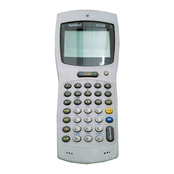
PDT 6100 Product Reference Guide Parts of the PDT 6100 Front View Top View Scan LED Scanner Scan Window Scan LED Display Charging LED Spectrum 24 Status LED Power Button Scan Bar Back View Keyboard Scan Head Scan Triggers Battery Bottom View Compartment Latch... -
Page 12: Accessories
SE 1200). Other scanning options will be available in future releases. Radio and Network Options ® Spectrum One Network The PDT 6110 includes an internal radio frequency transmitter/receiver for use in a Symbol Spectrum One network. ™ Spectrum24 Network The PDT 6140 includes an internal radio frequency transmitter/receiver for use in a Symbol Spectrum24 network. -
Page 13: Printers
PDT 6100 Product Reference Guide Printers The following printers can be used with Series 61XX terminals: Monarch Rascal Monarch Renegade ComTec 2-inch, 4-inch, and 6-inch receipt printers Miscellaneous Other Accessories A holster and other terminal storing/carrying devices are available for use with the PDT 6100. Before You Use the Terminal. -
Page 14: Chapter 2. Installing The Hardware
Chapter 2 Installing the Hardware Introduction The CRD 6100 cradle is used for RS-232 communications, charging, and storing the PDT 6100 terminal. This chapter provides information on setting up the cradle for charging the NiMH battery and communicating with a host or other serial device. Required Parts and Accessories Verify that you have the following cradle parts, cables, and other kits/accessories before attempting to mount or connect the cradle:... -
Page 15: Parts Of The Cradle
PDT 6100 Product Reference Guide Parts of the Cradle Spare Battery Charging Slot Terminal Slot RJ41 Connector Spare Battery Charging Slot Communications Spare Battery Charging LED Modem Connector (available as an option) Front View AC Power DB-25 Connector Communications Port Back View Figure 2-1. -
Page 16: Connecting The Cables
Installing the Hardware Connecting the Cables To connect the CRD 61XX’s communications cables and power supply: Power Supply Serial Cable Figure 2-2. Connecting the Cables 1. Plug the RS-232 serial cable in the communications port located on the back of the cradle. -
Page 17: Chapter 3. Batch And Spectrum One Initialization
Chapter 3 Batch and Spectrum One Initialization Before using the PDT 6100 system, perform the following procedures: Set up the CRD 6100 cradle (refer to Chapter 2, Installing the Hardware) Install the battery (refer to Chapter 6, Maintaining the PDT 6100 Terminal) Charge the battery (refer to Chapter 6, Maintaining the PDT 6100... -
Page 18: Communications
PDT 6100 Product Reference Guide Communications For terminals being used in a direct communications (batch) environment or a Spectrum One network environment, applications are transferred from a host computer over a communications line to the terminal. This procedure uses the SENDHEX program on the host computer and the Program Loader function (from Command Mode) on the PDT 6100. -
Page 19: Loading An Application
Batch and Spectrum One Initialization Loading an Application To download an application, initiate the communications software on the host computer and PDT 6100. Note: To cancel communications at any time during the session, press CLEAR on the PDT 6100. The session stops immediately. Communication parameters specified on host and PDT 6100 must match. -
Page 20: Initiate Terminal Communications
PDT 6100 Product Reference Guide Note: Versions of SENDHEX earlier than 3.0 do not support flow control. If you use an earlier version and encounter communication errors, use a lower baud rate. If you use a later version of SENDHEX and have communications errors, try setting flow control to XON/XOFF. - Page 21 Batch and Spectrum One Initialization 4. Press <ENTER> to erase the NVM. Wait while the NVM is erased. When complete, the program prompts for the communications parameters. 5. Baud Rate.The PDT 6100 displays: Comm Parameters Baud 38400 Scroll through the list using UpArrow or DownArrow. When the correct rate is displayed (38400 is recommended), press <ENTER>.
-
Page 22: Starting Communications
PDT 6100 Product Reference Guide Press the first letter of a flow control option (None, Xon/Xoff, or RTS/CTS), or scroll using UpArrow or DownArrow and press <ENTER> when the correct value is displayed. 9. Go to Starting Communications to continue. Starting Communications The PDT 6100 is ready to receive the program from the host PC and displays: Comm Parameters... -
Page 23: Ending Communications
Batch and Spectrum One Initialization Ending Communications To return to the Command Mode main menu: 1. Press <CLEAR> on the PDT 6100. 2. Power down the PDT 6100. 3. Remove the PDT 6100 from the cradle. 4. Reboot the PDT 6100 using the appropriate cold boot sequence described in Booting a Terminal on page 5-4. -
Page 24: Chapter 4. Spectrum24 ® Rf Terminal Setup
Chapter 4 ® Spectrum24 RF Terminal Setup Spectrum24 Terminals In Spectrum24 terminals, wireless connectivity is accomplished using standard communications protocols. Because they are standard, the protocols are generalized and take ® up considerably more space on the terminal’s NVM than was required for Spectrum One terminals. -
Page 25: Standard Spectrum24 Software
If your requirements are more advanced, refer to the Spectrum24 Network Development Kit documentation for more information on the Spectrum24 RF network, SLAODI.COM, the Symbol-provided ODI driver, and the configuration file setups required for various platforms. Boot Options & Internet Addressing... -
Page 26: Initializing The Pdt 6140
® Spectrum24 RF Terminal Setup Initializing the PDT 6140 Note: This section covers specific settings required on first booting the PDT 6140, out of the box. For a complete review of the CFG24 screens, refer to Appendix E, Spectrum24 Network and Flash Disk Utilities. - Page 27 PDT 6100 Product Reference Guide On the PDT 6140 screen, the top and bottom lines of the menu are displayed, and the remaining lines are viewed by scrolling. In this menu, pressing <CLEAR> has the same effect as selecting Exit. 4.
- Page 28 ® Spectrum24 RF Terminal Setup Table 4-1. Spectrum24 Configuration Parameters (Continued) Terminal Sleep Determines whether radio is powered off after the terminal enters Mode sleep mode due to inactivity. Refer to Appendix E for more information. The default value is “On”. Power Management If power management is set to PSP, the radio powers up only when there is traffic on the network.
- Page 29 PDT 6100 Product Reference Guide b. To change the Net Id, select Net Id from the CFG24 Menu. The Net Id screen (Figure 4-3) is displayed. NET ID Enter Net Id(hex): BkSp, Clear, Enter Figure 4-3. Net Id Screen To change the current Net Id value, backspace over the current value and type a new value, in hexadecimal format, in the range 101 to 1FE.
- Page 30 ® Spectrum24 RF Terminal Setup d. Select Default Router from the main configuration menu. The Default Router screen (Figure 4-5) is displayed. DEFAULT ROUTER Enter Default Router 157.235.93.178 BkSp, Clear, Enter Figure 4-5. Default Router Screen To change the current Default Router setting, backspace over the current value and type a new value, in decimal form.
- Page 31 PDT 6100 Product Reference Guide f. Select Diversity from the main configuration menu. The Diversity screen (Figure 4-7) is displayed. DIVERSITY 2 antennas (Yes/No) áâ, Clear, Enter Figure 4-7. Diversity Screen á â To change the current Diversity setting, use the “ ”...
- Page 32 ® Spectrum24 RF Terminal Setup h. Select Boot Mode from the main configuration menu. The Boot Mode screen (Figure 4-9) is displayed. BOOT MODE IP address from: Manual entry áâ, Clear, Enter Figure 4-9. Boot Mode Screen á â To change the current boot mode, use the “ ”...
-
Page 33: Initiating Network Connection
PDT 6100 Product Reference Guide The PDT 6140 displays the message: ...updating config data and proceeds with the initialization which writes the configuration values to a R/W non-volatile section of radio flash memory. Initiating Network Connection As the initialization continues, the terminal attempts to associate with the Spectrum24 AP using the default or newly entered Net Id. -
Page 34: Pdt 6140 Association With Ap Successful
® Spectrum24 RF Terminal Setup PDT 6140 Association with AP Successful If the association is successful, the terminal begins operating using the software files loaded on the flash disk. On first initialization, you probably don’t have applications loaded. Proceed with loading the applications as directed in Installing Application Software on Flash Disk. -
Page 35: Initiate Host Communications On The Pc
PDT 6100 Product Reference Guide Initiate Host Communications on the PC To update the hex image: 1. Power on the host computer. 2. On the PC, change to the directory where the application’s hex file is stored and type the following command at a DOS prompt: SENDHEX <hexfile>... -
Page 36: Initiate Pdt 6140 Communications
® Spectrum24 RF Terminal Setup Initiate PDT 6140 Communications 1. Place the PDT 6140 in the cradle and power it off. 2. Boot the PDT 6140 to command mode. a. Press <BK SP> and <SHIFT>. b. Press and release the Power button. c. - Page 37 0000, check the cable connections between the host PC and the cradle and repeat the process. If the problem persists, contact the Symbol Support Center for assistance. 4. After the download to each terminal is complete, re-initialize (cold boot) the PDT 6140 to finish copying the system files to the flash disk.
-
Page 38: Updating System Software On Flash Disk
ONLY: to load a new version of LWP greater than 3.03 if you experience serious difficulties if you are so directed by Symbol’s Technical Support staff. 1. Follow the instructions for Installing Application Software on Flash Disk on page 4- 11. -
Page 39: Multiple Applications On The Same Terminal
PDT 6100 Product Reference Guide The PDT 6140 finishes reformatting (if requested), copies the files to the flash disk, and executes them. Multiple Applications on the Same Terminal The system files (from LWP.HEX) fill over 200 KB of the flash disk’s 1 MB. Current standard applications such as STEP or TN clients require between 100 KB and 150 KB of flash disk. -
Page 40: Chapter 5. Operating The Pdt 6100
Chapter 5 Operating the PDT 6100 Introduction This chapter describes how to operate a PDT 6100 terminal, including: Powering the terminal on/off Booting the terminal Adjusting the display’s contrast Using the keyboard Entering data through the integrated scanner Communicating with other devices using the Charging and Communications Cable. -
Page 41: Powering A Terminal On And Off
PDT 6100 Product Reference Guide Powering a Terminal On and Off Because the terminal is battery powered, it is important to save power whenever possible. You can minimize power loss and increase battery life by turning the terminal off when data is not being entered. -
Page 42: Forcing Power Off
Operating the PDT 6100 Forcing Power Off If a terminal freezes in the middle of operation and pressing < > (PWR) does not power it off, you can force the system to power off, which reduces the drain on the batteries until you can download any collected data to the host system. -
Page 43: Booting A Terminal
PDT 6100 Product Reference Guide Booting a Terminal Powering the terminal on does not boot the system or initialize the program or data. To initialize the terminal, perform either a warm or cold boot. Warm Boot A warm boot resets the operating system while preserving the program and data on the RAM disk. -
Page 44: Cold-Boot Failure
If such a failure occurs, the terminal may need to be cold booted. If this does not solve the problem, call Symbol Support Center. More troubleshooting information is found in the publications listed at the beginning of this manual. -
Page 45: Adjusting The Display
PDT 6100 Product Reference Guide Adjusting the Display Backlighting The terminal’s backlight illuminates the display in dimly lit areas. Note: Use of backlighting can significantly reduce battery life. To turn the backlight on or off, press the following keys in sequence: <Func>... -
Page 46: The Pdt 6100 Keyboard
Operating the PDT 6100 The PDT 6100 Keyboard The keyboard is used for entering data and issuing commands to the terminal. Figure 5-1 illustrates the standard 35-key keyboard. For the other PDT 6100 keyboards, refer to Appendix The keys on the keyboard are distinguished as modifier keys and character keys. Because terminal keyboards have fewer keys than PC keyboards, each character key can produce more than the usual one or two characters. -
Page 47: Modifier Keys
PDT 6100 Product Reference Guide Figure 5-1. PDT 6100 Standard 35-Key Keyboard Modifier Keys The <Shift>, <Alpha>, <Func>, and <Ctrl> keys are modifier keys. When pressed individually or in certain combinations, these keys change the keyboard state and possibly the character produced by the character key subsequently pressed. -
Page 48: Key Descriptions
Operating the PDT 6100 Refer to Appendix B for the characters and operations produced by pressing a sequence of modifier keys on the standard terminal keyboards. These key assignments can be changed by an application. Refer to your application documentation for any special key assignments. Cancelling a Modifier Key To cancel the effect of a modifier key, press it again. -
Page 49: Scanning
PDT 6100 Product Reference Guide Scanning Before scanning can occur, the application must implement routines to support bar code scanning. For information on scanning applications and on programming the scanner, refer to the Series 3000 Application Development Kit. The PDT 6100 terminal supports an integrated 1-D standard scanning device. Setting the Trigger The integrated scanner has a unique trigger that the operator can configure. -
Page 50: Using The Integrated Laser Scanner
3. Point the PDT 6100 at the bar code and press the scan bar or a side trigger. Figure 5-3. Scanning a Bar Code 4. Ensure that the scan beam crosses all bars and spaces on the symbol, as shown below. Right... -
Page 51: Aiming: Hold At An Angle
PDT 6100 Product Reference Guide Aiming: Hold at an Angle Do not hold the 6100’s scan window directly over the bar code. Laser light reflecting directly back into the scan window from the bar code is known as specular reflection. This strong light can “blind”... - Page 52 Operating the PDT 6100 The best way to specify the appropriate working range is through a chart called a Decode Zone (Figure 5-5). A decode zone simply plots working range as a function of minimum element widths of bar code symbols. 33222012.eps Figure 5-5.
-
Page 53: Running Communications
PDT 6100 Product Reference Guide Running Communications Communicating with a Host The 6100 communicates with a host or printer through the CRD 6100 or the Charging and Communications Cable (CCC). To communicate with a host or printer through the CRD 6100: 1. -
Page 54: Radio Communications
Host PC (shown) or Printer Radio Communications The PDT 6110 operates in a Symbol Spectrum One RF network; the PDT 6140 operates in a Symbol Spectrum24 RF network. The Status LED indicates the state of the 6100’s connection to either of the RF networks: indicates that the radio is working and associated with an access point (Spectrum24) or base station (Spectrum One). -
Page 55: Communicating With A Printer
PDT 6100 Product Reference Guide Communicating With a Printer To connect the terminal to a printer, use the CCC or the appropriate printer cable. The following directions apply to the CCC: 1. Plug the CCC’s 10-pin RJ-41 connector into the PDT 6100 terminal’s serial port (refer to Figure 5-7). -
Page 56: Chapter 6. Maintaining The Pdt 6100 Terminal
Chapter 6 Maintaining the PDT 6100 Terminal Batteries The PDT 6100 terminal’s primary power is provided by a nickel metal hydride (NiMH) battery pack. Battery Life Many factors affect battery pack life, including temperature, battery age, and data collection method. Uses and operating conditions which affect battery life are: scanning “power save”... -
Page 57: When To Replace Or Recharge Batteries
PDT 6100 Product Reference Guide Table 6-1. Battery Life: PDT 6100 Battery Type Input Method Approx. Operating Approx. Operating Approx. Operating Time: PDT 6100 Time: PDT 6110 Time: PDT 6140 1500 mAh NiMH Keyboard 50 hours 45 hours 48 hours Laser Scanner 6400 + scans 6100 + scans... -
Page 58: Replacement Batteries
15 minutes while batteries are replaced. The supercap does not provide enough power to operate the terminal. On receiving a low battery message, replace or recharge the primary batteries immediately. Replacement Batteries A rechargeable 1500 mAh NiMH battery pack, p/n 21-33061-01, can be ordered from Symbol Technologies. -
Page 59: Installing A New Or Recharged Battery Pack
PDT 6100 Product Reference Guide Installing a New or Recharged Battery Pack To install a new or recharged NiMH battery: 1. Turn the battery pack latch counterclockwise and remove the battery compartment door. Figure 6-1. Removing the Battery Compartment Door 2. -
Page 60: Charging The Battery
Maintaining the PDT 6100 Terminal 4. Replace the battery compartment door (Figure 6-3). Figure 6-3. Replacing the Battery Compartment Door 5. Turn the latch clockwise to secure the battery. Charging the Battery In a Terminal Seated in a CRD 6100 To charge the NiMH battery in the PDT 6100: 1. - Page 61 PDT 6100 Product Reference Guide Using the CCC The optional CCC provides power from a wall-mounted power supply for recharging the NiMH battery while the 6100 is in use. To connect the 6100 and the CCC: 1. Plug the CCC’s 10-pin RJ41 connector in the 6100’s base. 2.
-
Page 62: Recharging A Spare Battery Pack
Maintaining the PDT 6100 Terminal Recharging a Spare Battery Pack To recharge a spare battery pack in the cradle: 1. Insert the battery pack sideways, contacts down, into the spare battery slot, with the tab facing either the right or left side of the cradle. 2. -
Page 63: Cleaning
PDT 6100 Product Reference Guide Battery Charging Tips For maximum capacity and battery life: Charge at temperatures between 0 C and 40 C (32 F and 104 F). Optimum charging occurs at room temperature (about 20 C to 25 C). Above or below that range, batteries may not charge to rated capacity. -
Page 64: Chapter 7. Error Recovery And Troubleshooting
Chapter 7 Error Recovery and Troubleshooting This chapter provides information to assist in basic trouble analysis and correction for the PDT 6100, including: Error messages Troubleshooting start-up failures Troubleshooting Spectrum24 terminals Running the self test function Self test summaries Keyboard test Running memory transfer Scanning problems. -
Page 65: Troubleshooting
PDT 6100 Product Reference Guide Table 7-1. Error Messages Message Explanation Double Key Error Two or more keys were pressed at the same time. This does not include boot sequences (refer to Chapter 5, Operating the PDT 6100, for boot sequences). Low Battery The battery pack should be recharged or replaced as soon as possible. -
Page 66: Spectrum24 Terminal (6140)
Error Recovery and Troubleshooting If such a failure occurs, cold boot the terminal again. If this does not solve the problem, call Symbol Customer Support. More troubleshooting information is found in the documentation listed in the Related Publications on page -6... -
Page 67: Self Test Function
PDT 6100 Product Reference Guide Self Test Function PDT 6100 terminal includes a series of self tests which verify that terminal hardware components are operating properly. Run self test if you suspect a problem with the hardware. Except for keyboard testing, no operator input is necessary after selecting a test screen. Running the Self Test Access the Self Test function from the Command Mode menu: 1. -
Page 68: Keyboard Test
Error Recovery and Troubleshooting Keyboard Test Keyboard testing can be performed while the terminal displays Config Screen 1 results. Test any keys except Clear and PWR. When you press a key, the corresponding key code is displayed on the top row to the right of the test name. Table 7-3 lists the codes for each key. -
Page 69: Memory Transfer Program
PDT 6100 Product Reference Guide Memory Transfer Program Command Mode includes a memory transfer utility that transfers data from a terminal to a host PC for program troubleshooting. Programmers can analyze an application using tools provided in the Series 3000 Application Development Kit and described in the Series 3000 Application Programmer’s Reference Manual. -
Page 70: Set Communications Parameters
Error Recovery and Troubleshooting 5. Plug in the cradle, if used. 33222011.eps Figure 7-2. Cradle Connections for Memory Transfer Set Communications Parameters Host 1. Start the Communications program on the host PC. 2. Set up the host communication parameters (these parameters must match the terminal’s parameters). - Page 71 PDT 6100 Product Reference Guide 3. Select the range of memory to transfer by pressing the first letter of the desired range (All, Range, or None), or use the <UpArrow> or <DownArrow> and press <Enter>. If you select All, the program skips to the range verification screen (step 7). If you select Range, the screen displays: Use Arrow Keys Start...
- Page 72 Error Recovery and Troubleshooting 8. Specify the baud rate. Use the <UpArrow> and <DownArrow> to scroll through the list of baud rates until the correct rate is displayed, and press <Enter>. (Flow control may be necessary at 38400 bps and higher.) 9.
-
Page 73: Scanning Problems
Check to see if you are scanning from the proper distance. Try scanning a test symbol of the symbology you are trying to read. Your terminal operates but scanned data is not displayed correctly? Check the system power. -
Page 74: Appendix A Port Pin-Outs
Appendix A Port Pin-Outs This appendix provides reference information for PDT 6100 ports and mappings for a null modem cable. Pinouts for PDT 6100 Serial Devices The RJ41 connector is located in the base of the terminal. Table A-1. RJ-41 Connector Pin# Signal Description... -
Page 75: Appendix B Keyboard Layouts
Appendix B Keyboard Layouts The following pages show the characters and character sequences produced by the 35- key PDT 6100 keyboard when modified with the appropriate key sequence. For instance, Figure B-3 shows what characters the keys produce when you press the Alpha key first, Figure B-7 shows what characters the keys produce when you press the Func key then the Ctrl key. - Page 76 PDT 6100 Product Reference Guide Figure B-2. 35-Key Unmodified PDT 6100 Keyboard Figure B-3. 35-Key Alpha Key Modified PDT 6100 Keyboard...
- Page 77 Keyboard Layouts " < & > 33222004.eps Figure B-4. 35-Key Shift Key Modified PDT 6100 Keyboard Figure B-5. 35-Key Control Key PDT Modified PDT 6100 Keyboard...
- Page 78 PDT 6100 Product Reference Guide 33222003.eps Figure B-6. 35-Key Function Key Modified PDT 6100 Keyboard 33222005.eps Figure B-7. 35-Key Alt Key Modified PDT 6100 Keyboard...
- Page 79 Keyboard Layouts < 33222002.eps Figure B-8. 35-Key Shift + Func Modified PDT 6100 Keyboard 33322006.eps Figure B-9. 35-Key Ctrl + Func Modified PDT 6100 Keyboard...
- Page 80 PDT 6100 Product Reference Guide 33222007.eps Figure B-10. 35-Key Alt + Func PDT 6100 Keyboard...
-
Page 81: Appendix C Communications Status Codes
Appendix C Communications Status Codes The program loader status code consists of four hexadecimal digits which indicate whether or not the transfer was successful, and if not, the source of the communications error. A status code of 0000 indicates success; any other code indicates failure. Table C-1 on page C-2 lists the failures associated with the status codes. - Page 82 PDT 6100 Product Reference Guide Table C-1. Communications Status Codes Status Code Meaning 0002 Receive overrun error 0004 Receive parity error 0008 Receive framing error 0010 Programming voltage not present 0020 Data Set Ready or Carrier Detect not detected on open 0040 Lost DSR while receiving 0080...
-
Page 83: Appendix D. Specifications
Appendix D Specifications Environment The terminal’s operating conditions are listed in Table D-1, Environmental Specifications. Table D-1. Environmental Specifications Condition Range Operating Temperature -4° to 122°F 0° to 40°C Storage Temperature -40° to 158°F -40° to 60°C Humidity (Operating) 5% to 95% non-condensing @ 50°C for 168 hours Altitude Up to 10,000 feet... -
Page 84: Storage
PDT 6100 Product Reference Guide Storage If the terminal is not used for more than a week, store it in a cool, dry place, away from dust. Remove the battery and repack the terminal in its original shipping container. For a storage period of a few days, the batteries can remain in the terminal. If the batteries are left in the terminal for an extended period of time, data stored in the terminal may be lost. -
Page 85: Appendix E Spectrum24 Network And Flash Disk Utilities
Appendix E Spectrum24 Network and Flash Disk Utilities Introduction Some supplemental utilities are provided for working with the flash disk in addition to the Flash disk driver and utilities provided in the Series 3000 ADK. These utilities include: CFG24 executes from a DOS prompt to change parameters for radio communications. -
Page 86: Cfg24
PDT 6100 Product Reference Guide CFG24 The CFG24 utility enables the terminal operator to configure radio communications parameters. This utility must be run after the radio driver loads because the configuration parameters are saved in the radio card’s flash memory, which is accessed using the radio driver services. - Page 87 Initially, CFG24 presents the main menu shown in Figure E-1. CONFIGURATOR 1.XX View config params Net Id Subnet Mask Default Router Terminal IP Address Diversity Terminal Sleep Mode Boot Mode Power Management Exit áâ, Clear, Enter Figure E-1. CFG24 Main Menu The current selectable option appears in reverse video.
- Page 88 PDT 6100 Product Reference Guide 2. Select Net Id from the CFG24 Menu. The Net Id screen (Figure E-3) is displayed. NET ID Enter Net Id(hex): BkSp, Clear, Enter Figure E-3. Net Id Screen The Net Id identifies the radio network and differentiates between different radio networks.
- Page 89 4. Select Default Router from the main configuration menu. The Default Router screen (Figure E-5) is displayed. DEFAULT ROUTER Enter Default Router 157.235.93.178 BkSp, Clear, Enter Figure E-5. Default Router Screen The default router address is the address of the node where all packets going to remote networks are sent.
- Page 90 PDT 6100 Product Reference Guide To change the current Terminal IP Address, backspace over the current value and type a new value in decimal form. Each part of the four-part address must be in the range 0 to 255. Press <ENTER> to effect the change. Press <CLEAR> to exit without changes. 6.
- Page 91 If boot mode is set to “DHCP” when the terminal is initialized, the process is the same as for BOOTP, except the Dynamic Host Configuration Protocol is used. Symbol’s BOOTP program accepts setting the following network parameters from the BOOTP and DHCP parameters: Sub-net Mask Default Router (first address from the router list)
- Page 92 PDT 6100 Product Reference Guide á â To change the current boot mode setting, use the “ ” and “ ” keys to toggle between the three valid settings. Press <ENTER> to effect the change. Press <CLEAR> to exit without changes. 9.
-
Page 93: Bootp
BOOTP The BOOTP program gets the IP address and sets up communications parameters for use by other parts of the system. How the program works depends on which boot mode setting was selected in CFG24, as follows: If “Boot” was selected, a TCP/IP BOOTP request is broadcasted to the network. Boot servers on the network configured to respond send a response. -
Page 94: Output
PDT 6100 Product Reference Guide Output The following parameters in the radio flash save area are updated if changed by a BOOTP or DHCP process: Sub-network Mask BOOTP or DHCP response may change the sub-network mask. If no change is received from the BOOTP or DHCP response, uses the default of 255.0.0.0. -
Page 95: Stat24
STAT24 STAT24 is a Terminate and Stay Resident (TSR) program used to provide the status of the radio connection. It can also be used to check for RF association and alternate actions in batch files depending on the association status. This utility is used mainly to check for associations with an AP when RF difficulties are experienced. - Page 96 PDT 6100 Product Reference Guide The fields in Figure E-11 are interpreted as follows: Line 1 Title and version number of STAT24. Line 2 The terminal’s IEEE address. Line 3 The version and date of the adapter firmware. Line 4 The IEEE (MAC) address of the Access Point the terminal is associated with.
-
Page 97: Diag24
DIAG24 DIAG24 is intended for use in two situations: As a connectivity tool, using a ping that is not re-tried on transmission errors. This test is intrusive as pings are sent as fast as possible. As a diagnostic tool for potential radio problems. It can eliminate or confirm that the traffic problems are in the radio portion of the network. - Page 98 PDT 6100 Product Reference Guide Whichever mode was selected from the DIAG24 menu, the set-up menus that follow are the same. The title line of the first screen (Figure E-13) indicates the selected test mode: AP PING TEST for selection 1; FIELD DIAGNOSTICS for selection 2. <Test Mode>...
- Page 99 5. Select the ping message size in the Message Size screen shown in Figure E-14. Press the corresponding number to make the selection and advance to the next screen. Press Q or <CLEAR> to return to the main menu. <Test Mode> NUMBER OF PINGS 1.
-
Page 100: Ping Tests
PDT 6100 Product Reference Guide Ping Tests During an AP ping test, the screen shown in Figure E-17 is displayed and continuously updated. AP PING TEST A Cnt Err AP RS 04 36 04 36 04 36 TMO 04 36 04 36 Press ‘Q’... -
Page 101: Field Diagnostics
Figure E-18, the first detail line reads “*6*2...” showing that the real values for the counters in the second and subsequent detail lines are 600, 057, and 2,002. Press <Q> or <CLEAR> to terminate the test and return to the DIAG24 menu. AP PING TEST Total secs = 7.4 Pings = 100... -
Page 102: Flash.bat
PDT 6100 Product Reference Guide indication of error type if there was an error, and the AP identifier of the AP that responded to the message. When the test stops, a summary screen is displayed (Figure E-21). FIELD DIAGNOSTICS Total secs = 8.2 Pings = 100 Packet size = 512 Retries = 6... -
Page 103: Copying Files To Flash Disk
Note: There is no mention of the E: drive in the command Copying Files to Flash Disk To copy files to flash disk, use the command: FLASH COPY <filename> \ For example: FLASH COPY NET.CFG \ copies NET.CFG, the protocol stack configuration file, from the current directory (normally D:) to the root directory on flash disk, and FLASH COPY E:\SVTP\CS1.CFG \STEP copies CS1.CFG from the SVTP directory on flash disk to the STEP directory on flash disk. - Page 104 A pattern of variable-width bars and spaces which represents numeric or alphanumeric data in machine-readable form. The general format of a bar code symbol consists of a leading margin, start character, data or message character, check character (if any), stop character, and trailing margin. Within this framework, each recognizable symbology uses its own unique format.
- Page 105 0 to 9 and six additional characters: (- $ : / , +). Code 128 A high density symbology which allows the controller to encode all 128 ASCII characters without adding extra symbol elements. Code 3 of 9 (Code 39) A versatile and widely used alphanumeric bar code symbology with a set of 43 character types, including all uppercase letters, numerals from 0 to 9, and 7 special characters (- .
- Page 106 Glossary Development Kits A set of software tools provided to customers to help them create applications for their terminals. See ADK. Discrete 2 of 5 A binary bar code symbology representing each character by a group of five bars, two of which are wide. The location of wide bars in the group determines which character is encoded;...
- Page 107 PDT 6100 Product Reference Guide IOCTL Input/Output Control. Internet Protocol. Local Area Network. Refer to Liquid Crystal Display. Refer to Light Emitting Diode. Light Emitting Diode A low power electronic light source commonly used as an (LED) indicator light. Uses less power than incandescent light bulb but more than a Liquid Crystal Display (LCD).
- Page 108 2. Photodetector - registers the difference in reflected light (more light reflected from spaces). 3. Signal conditioning circuit - transforms optical detector output into a digitized bar pattern. SE 900 Symbol's miniature laser scan modules that can be integrated into portable computing devices. SHIP Symbol Host Interface Program. Spectrum24 Symbol’s frequency-hopping, spread spectrum cellular network.
- Page 109 PDT 6100 Product Reference Guide Terminate and Stay A program under DOS that ends its foreground execution to Resident (TSR) remain resident in memory to service hardware/software interrupts, providing background operation. It remains in memory and may provide services on behalf of other DOS programs. Transmission Control A suite of the standard network protocols that were originally Protocol/Internet Protocol...
- Page 110 Index applications Numerics single vs. multiple ....4-11 3140 associating with access point ... 4-10 Spectrum24 terminal ....1-4 6100 initialization procedures .
- Page 111 Symbol ....E-7 single-slot ..... . . 1-3 overview .
- Page 112 Index procedure ....3-3–3-7 DHCP ......4-2 selecting communications parameters .
- Page 113 PDT 6100 Product Reference Guide memory transfer ....5-5, port pin-outs ..... . . A-1 ending communications .
- Page 114 Index scan ......5-12 loading system files ....3-1 real time clock .
- Page 115 TSRs Symbol Support Center ....7 STAT24 ..... . . E-11 system software Spectrum24 .
- Page 116 We’d like to know what you think about this Manual. Please take a moment to fill out this questionaire and fax this form to: (516) 738-3318, or mail to: Symbol Technologies, Inc. One Symbol Plaza M/S B-4 Holtsville, NY 11742-1300 Attn: Technical Publications Manager IMPORTANT: If you need product support, please call the appropriate cus- tomer support number provided.