
Related Manuals for Omron Pioneer LX


Summary of Contents for Omron Pioneer LX
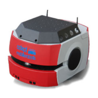
- Page 1 Omron Adept Mobile Robots Platforms for Research, Education and Development Pioneer LX User's Guide Rev. D November 2017...
- Page 2 Any trademarks from other companies used in this publication are the property of those respective companies. Created in the United States of America Omron Adept MobileRobots • 10 Columbia Drive • Amherst, NH 03450 • USA • Phone +1 603 881 7960 • www.mobilerobots.com...
-
Page 3: Table Of Contents
Table of Contents Table of Contents Chapter 1: Introduction ..........8 Product Description ......................8 MTX Generation and Pioneer Compatibility ..................8 Body, Drive and Control ........................9 What's Included - Basic Components ....................9 Optional Accessories, Parts, Components and Attachments (partial list) ........11 User-Supplied Components / System Requirements .............. - Page 4 Before Unpacking the Platform ..................25 Unpacking ......................... 25 Lifting the Platform ..........................27 Repacking for Relocation ....................29 Installing a Pioneer LX System ..................29 Installing the Battery ........................... 29 Attaching Optional Accessories ......................31 Installing the Charging Station......................31 Embedded Computer Setup ...................
- Page 5 MTX-Lynx Core Front, Upper ......................66 MTX-Lynx Core Rear, Upper ......................73 Core, Side ............................. 80 2.3 Internal Pioneer LX Core Connections ..............80 Lynx Internal Data Pinouts ........................ 82 Pioneer LX Internal Power Pinouts ....................84 Chapter 8: Maintenance ..........87 2.1 Safety Aspects While Performing Maintenance...........
- Page 6 Table of Contents Maintaining Batteries.......................... 91 Replacing the Battery .......................... 91 Balance and Maintainence Charging ....................93 Removing and Installing Covers ..................93 Cover Removal ............................ 94 Cover Installation ..........................96 Replacing Non-Periodic Parts ..................98 Charging Station Roller and Bearing ....................99 Charging Station AC Power Fuse .....................
- Page 7 Table of Contents Opening the session—OPEN ......................128 Keeping the Beat—PULSE ....................... 128 Closing the connection—CLOSE..................... 128 2.7 CONFIG Packet and CONFIG command ............128 2.8 Joystick Packet ......................132 Page 7 of 134...
-
Page 8: Chapter 1: Introduction
Refer to Connectivity on page 65, for information on the available connectors.. For some projects, you may want to customize the Pioneer LX with a payload, attached to the top of the platform, such as sensors, manipulators, extra structure. Refer to Payloads on page 57 for general information on designing a payload. -
Page 9: Body, Drive And Control
IO packets. Two versions of the Pioneer LX have been produced. The first version is based on the Adept Lynx mobile robot, and features front and rear sonar sensors in addition to the primary laser rangefinder sensor. The second version is based on the Omron-Adept LD series mobile robot, and features a secondary laser rangefinder instead of front sonar, as well as various minor changes. - Page 10 Table of Contents Top plate with operator panel, controls and connectors Removable equipment mounting deck (optional use) One fully-charged battery This is shipped separately from the platform, due to air shipping regulations. Automated charging station (docking station) Allows the platform to charge itself, without user intervention.
-
Page 11: Optional Accessories, Parts, Components And Attachments (Partial List)
Power outlet for docking station (115VAC or 220VAC) Software Overview The Pioneer LX comes with the following software preinstalled and ready to use. Software packages are also provided on the included CDROM, and may be downloaded from http://support.mobilerobots.com. See Programming on page 51 for more information on writing software. - Page 12 Table of Contents ARIA ARIA is the core development library or SDK for use with the robot. It is an open source C++ library (with interfaces also available for Python, Java and Matlab). ARIA is available with all robots. /usr/local/Aria C:\Program On Linux ARIA can be found at , and on Windows at...
-
Page 13: Operating Environment
MobileRobots or the original manufacturer of the device. These libraries can be downloaded from http://support.mobilerobots.com/wiki/Software. All other accessory devices are supported in ARIA. Operating Environment The Pioneer LX is designed to operate in an environment that is wheelchair accessible. Care must be taken to avoid: glass doors and walls ... - Page 14 5° to 40° C (41° to 104° F) Humidity 5 to 95%, non-condensing The Pioneer LX is not intended for use in hazardous environments (explosive gas, water, dust, oil mist). It has an IP rating of IP-40. Page 14 of 134...
-
Page 15: Dangers, Warnings, Cautions, And Notes
Table of Contents 2.3 Dangers, Warnings, Cautions, and Notes There are six levels of special alert notation used in this manual. In descending order of importance, they are: DANGER: This indicates an imminently hazardous electrical situation which, if not avoided, will result in death or serious injury. DANGER: This indicates an imminently hazardous situation which, if not avoided, will result in death or serious injury. -
Page 16: What To Do In An Emergency /Abnormal Situation
Table of Contents What To Do in an Emergency /Abnormal Situation Press the E-Stop button (a red push-button on a yellow background) and then follow the internal procedures of your company or organization for an emergency situation. If a fire occurs, use a type D extinguisher: foam, dry chemical, or CO . -
Page 17: Falling Hazards
Table of Contents Do not ride on the platform. Do not exceed the maximum weight limit. Payload decreases as slope increases. Do not exceed the maximum recommended speed, acceleration, deceleration, or rotation limits. See Center of Gravity on page 54 and Acceleration, Deceleration, and Rotation Limits on page 49. ... -
Page 18: Electrical Hazards
Avoid shorting the terminals of the battery. Do not use any charger not supplied by Omron Adept Technologies, Inc. If any liquid is spilled on the AIV, power off the AIV, clean up all possible liquid, and allow the AIV to air dry thoroughly before restoring power. -
Page 19: Qualification Of Personnel
Providing an interlock between the robot and facility equipment is the user’s responsibility. Configurable Warning Buzzer A warning buzzer is available in LD-series Pioneer LX robots, which may be connected to the core if desired. It is the user’s responsibility to connect, test and configure this buzzer as appropriate for the facility in which the robot will be operating. -
Page 20: Environment
Table of Contents Environment General Environmental Conditions It is the end-user’s responsibility to ensure that the operating environment of the platform remains safe for the platform. If there are areas that are not safe for the platform to travel in, those areas should be physically blocked off so that the platform’s scanning laser will detect the barriers, and the platform will not attempt to drive there. -
Page 21: Intended Use
The body of the robot must not come into contact with liquids. The drive wheels can tolerate damp floors, but the body of the robot must remain dry. If there is any doubt concerning the application, ask Omron Adept Technologies, Inc. to determine if it is an intended use or not. Robot Modifications If the user or integrator makes any changes to the platform, it is their responsibility to ensure that there are no sharp edges, corners, or protrusions. -
Page 22: Warning Label
In case of a fire, use a type D extinguisher: foam, dry chemical, or CO Additional Safety Information Omron Adept Technologies, Inc. provides other sources for more safety information: Mobile Robot LD Safety Guide Mobile Robot LD Safety Guide provides detailed information on safety for LD Platform based mobile robots. -
Page 23: Factory Repairs
Table of Contents Factory Repairs If after reading this manual, you are having hardware problems with your robot system and are sure that it needs repair, contact us at: support@mobilerobots.com In the body of your e-mail message, provide your robot’s serial number and describe the problem you are having in as much detail as possible. -
Page 24: Chapter 2: Setup
Transport and Storage Platform The Pioneer LX must be shipped and stored in a temperature-controlled environment, between 5° and 70° C (41° to 158° F). The recommended humidity range is 5 to 95%, non-condensing. It should be shipped and stored in the supplied shipping container, which is designed to prevent damage from normal shock and vibration. -
Page 25: Battery Storage
Retain the crates and packaging materials. These items may be necessary to settle claims or, at a later date, to relocate the equipment. The Pioneer LX comes packed in a wooden crate, lined with foam. It is mounted on a pallet, with a wooden cover. See the following two figures. - Page 26 Table of Contents Additional optional accessories including cameras, arms, etc. may be shipped in separate boxes. Retain all parts and fasteners removed for possible repacking Remove the four Klimp clips from the front panel. Remove the two lag screws at the bottom of each end of the crate cover. Undo the four spring-loaded latches and remove the front panel of the crate.
-
Page 27: Lifting The Platform
Table of Contents To move the robot, install the battery (see below), power on, and use the brake release button or joystick drive mode. Lifting the Platform CAUTION: You can damage the platform if you lift it incorrectly. Use two people to lift the platform out of its crate. ... - Page 28 Table of Contents Upper Side of Laser Slot, at Sides, NOT at Center Rear Lifting Points Lift near the center of the platform, where the cover has a raised section. Do not lift anywhere else. Lift the metal frame behind the plastic body panels, not the plastic body panel. Refer to the following figures: Page 28 of 134...
-
Page 29: Repacking For Relocation
Installing a Pioneer LX System Installing the Battery Your Pioneer LX comes fully-assembled, but with battery packed separately. NOTE: The battery is partially discharged for shipping. To fully charge the battery, refer to the section on charging. Air shipping regulations require that the battery be shipped separately, partially discharged. - Page 30 Table of Contents Battery Compartment Door (keys are zip-tied for shipping) Battery Recesses, for Gripping The battery is designed to be lifted and replaced by one person, using one hand in each of the grips, as shown in the following figure. Lifting the Battery The connectors for power and data go toward the rear of the platform.
-
Page 31: Attaching Optional Accessories
The top of the charging station foot is spring-loaded, and lifts off of the bottom of the foot slightly to accommodate variations in the floor surface. The weight of the Pioneer LX will push the top of the foot down. - Page 32 Table of Contents Charging Station, Wall Mount Screw the two shoulder bolts, each with a washer, into the rear of the charging station. The shoulder bolts are M5 x 4, stainless steel. Their locations are shown in the following figure. Tighten to 9 N-m (80 in-lb).
- Page 33 Table of Contents Example of Charging Station Wall Mount Bracket Installation Lower the charging station down, so the two bolts on the back of the charging station slide into the bracket, to secure the charging station to the wall. Floor-mount, without Floor Plate Screw the base of the charging station directly to the floor, using three user-supplied screws.
- Page 34 Table of Contents Underside of Charging Station Foot, Showing Screw Locations NOTE: These are the three locations for the M4 x 12 flat-head screws. Two are already in place, and need to be removed before attaching the plate. Charging Station, Mounted on Floor Plate Charging Station Floor Plate Dimensions Page 34 of 134...
-
Page 35: Embedded Computer Setup
Table of Contents All mounting methods Install the power cord and turn the power switch to ON. The power switch is next to the power plug. The blue power LED indicator should light. Charging Station Contact Adjustment The contacts on the charging station have five height settings. The station is shipped with the height in the middle setting, which should be correct in most cases. -
Page 36: Remote Access
Table of Contents The default password for the guest and root users on Linux, and the Administrator account on Windows, is mobilerobots. We recommend changing these default passwords. Remote Access If the onboard computer is running Linux, a remote login connection can be made using ssh (Secure Shell). - Page 37 Table of Contents See http://support.mobilerobots.com/wiki/Linux_Network_Configuration for more information on configuring Linux network settings. Configuring Windows Network Settings To change network settings in Windows, open Contol Panel from the Start menu. Open the Network or Network and Sharing Center control panel, and choose Change adapter settings. See http://support.mobilerobots.com/wiki/Windows_Network_Configuration for more information on configuring Windows network settings.
-
Page 38: Aria Demo
Table of Contents Chapter 3: Software Demonstrations and Quick Start This section will walk you through running some example programs from ARIA and MOGS. You can run these examples either on the robot embedded computer, or, you can simulate the robot on your own laptop or desktop workstation, by first simply running the MobileSim simulator and selecting the pioneer-lx robot type (however, not all hardware features and devices are simulated.) ARIA Demo... -
Page 39: Arnl Demo Server And Mobileeyes
Table of Contents Demo will connect to the robot, displaying information about the connection and the robot such as Name and Subtype. Demo starts in teleoperation/drive mode. Use the arrow keys or robot joystick to drive the robot. Use the space bar to stop. - Page 40 Table of Contents Double click the arnlServer icon on the desktop to run arnlServer, or run it from the Start menu (All Programs -> MobileRobots -> ARNL-> arnlServer). Or, to run it from a command prompt: Open a command prompt (Start->All Programs->Accessories->Command Prompt) cd “\Program Change to the ARNL programs directory with the following command: Files\MobileRobots\ARNL\bin”...
-
Page 41: Chapter 4: Components And Operation
Note, before proceeding, you need to have performed the steps covered in the Setup and Getting Started chapters. Operating Environment The Pioneer LX is designed to operate in an environment that is wheelchair accessible. Care must be taken to avoid: ... -
Page 42: Typical Operation
ON button. Note: The Pioneer LX is always powered on when attached to the charging station, and will not turn off if the OFF button is pressed. To power off the Pioneer LX, hold the BRAKE RELEASE button and carefully move it off the charging station. -
Page 43: Battery Indicators And Controls
Table of Contents Recharge time is approximately 3.5 hours. The robot's motors will be automatically disabled while on the charging station. Battery Indicators and Controls The battery module has one push-button and four LEDs. From left to right, they indicate: LED Color Meaning Error condition... -
Page 44: Manually Charging The Battery
Table of Contents detect the shape of the charging station, and then turn around and back onto the charging station to charge. Note, there may be up to a 10-second delay between when a robot docks and when the charging LED turns on. -
Page 45: Operator Control Panel
Table of Contents Outside the Platform A battery can be manually charged outside of the platform, by using the connector on the left side of the charging station with the provided charging cable. This method may be used for charging a spare battery, while the second battery is still in the platform, and the platform is in use. -
Page 46: E-Stop Button
Table of Contents E-Stop Button When pressed, the red, latching push-button removes power from the platform’s motors and from the E- Stop-controlled power port after a 1 second delay. To reset the E-Stop, twist the button slightly, so it pops When the E-Stop button is pressed, the robot's motors will be disabled, and must be re-enabled by software (using the ENABLE command). -
Page 47: Joystick
OUT1 (green) on. Joystick The joystick plugs into the left side of the Pioneer LX, under the small access panel at the upper-right corner of the platform. It may be used with running software (such as ARIA demo or ARNL arnlServer) to manually drive the robot. -
Page 48: Mtx-Lynx Core Diagnostic Indicators
The joystick’s GOAL button (secondary button) can be used to mark positions while making a map scan for ARNL, or its state can be detected for any purpose by your own custom software. WARNING: The Pioneer LX may not sense obstacles while manually operated with the joystick, unless running software does so.. -
Page 49: Sensors
Table of Contents Indicator Meaning The computer and the robot controller are communicating DRIVE The motors are enabled and the drive wheels are under servo control ESTOP E-Stop button engaged 20 V power is available 12 V power is available 5 V power is available VBAT Raw battery power is available... -
Page 50: Sonar
One bumper panel, with two pairs of sensors, is mounted at the front of the platform, should the obstacle- avoidance systems fail to detect an obstacle. The Pioneer LX indicates a left bumper hit (0) to software if only the left side of the bumper panel is triggered, a middle bumper hit (1) if both sides of the bumper panel are triggered, and a right bumper hit (2) if the right side is triggered. -
Page 51: Chapter 5: Programming
Chapter 5: Programming All Pioneer 2/3-compatible platforms use a two-tier architecture. Pioneer LX’s microcontroller with embedded MARC firmware manages all the details of the robot’s mobility and internal systems including implementing velocity control of the robot platform, coordinating the motors, receiving encoder data, integrating encoder and gyro data to determine an estimate for robot position, managing power to all components, and more. -
Page 52: Robots In Motion
117 for a description of this protocol.) Robots in Motion When Pioneer LX receives a motion command, it accelerates or decelerates the robot according to acceleration or deceleration parameters previously set until the platform either achieves the requested speed (for velocity commands) or nears the requested movement distance (when performing MOVE, HEAD and DHEAD commands). -
Page 53: Position Integration
USB interfaces of the onboard computer (via FTDI USB-serial adapters). ARIA has been preconfigured on the Pioneer LX embedded computer to connect to the robot controller via the correct interface and using the correct baud rate as shown in the table below. On Linux, the /etc/Aria.args... -
Page 54: Windows Com Port Assignment
Windows assigns COM port names based on unique USB device identifiers, so if you reinstall Windows or remove and reinstall the FTDI drivers, default COM port names on an individual Pioneer LX robot will be arbitrary and must be reassigned as follows. COM port names can be reassigned by clicking Adanced... -
Page 55: Further Programming Information
Table of Contents Serial Port B COM4 Location: Port_#0006.Hub_#0000 Serial Port C COM5 (Loc56) Serial Port D COM6 Serial Port A COM7 EHCI USB Composite Device 7 Location: Port_#0007.Hub_#0000 Serial Port B COM8 (Loc57) Serial Port C COM9 Serial Port D COM10 Serial Port A COM11 EHCI USB Composite Device 8... - Page 56 Table of Contents http://support.mobilerobots.com/wiki/aria-users Page 56 of 134...
-
Page 57: Chapter 6: Payloads
Your payload may be added to the equipment mounting deck (see below), or you may replace the deck and/or top plate with your payload. The Pioneer LX may be used with or without the top plate or deck or both. The front portion of the top plate may be removed by removing the hinge from rear portion. The rear portion may be removed by detaching the USB, serial and VGA ports, wifi antennas, and LCD panel. -
Page 58: Power Consumption
Table of Contents A heavy payload, with most of its weight concentrated just above the Pioneer LX, will be much more stable than the same weight payload in which the weight is either off-center or high above the top of the platform. -
Page 59: Payload Bay Access
Payload Bay Access The area beneath the top plate is the payload bay. You will occasionally need to access the Pioneer LX and the connectors in the payload bay. This is where you can access all of the platform power and I/O connectors. -
Page 60: Center Of Gravity
Table of Contents Take care to keep all of the payload higher than the top of the Pioneer LX. If any of the platform's sensors get blocked, it won't be able to function normally. This is critical in the case of the laser rangefinder. - Page 61 Table of Contents The three following figures show the calculations of safe placements for the center of gravity for payloads with the weights listed. The center of gravity, in each instance, needs to be within the area shown. All units are mm. NOTE: These figures show the limits of where the payload center of gravity can be placed.
- Page 62 Table of Contents 60 kg Page 62 of 134...
-
Page 63: Mounting Deck
M3 screws. The mounting deck is attached to the frame of the Pioneer LX via M5 screws on each side and may be removed to access the interior payload bay or to remove equipment for maintenance or changes for different projects. -
Page 64: Connections Between Platform And Payload
Table of Contents Connections Between Platform and Payload The Pioneer LX provides a variety of I/O and power connections, which you can use to make your robot more effective. The Operator screen, E-Stop, Brake-release, ON, and OFF may be relocated if desired. This allows you to add the robot controls somewhere on your payload with just one cable. -
Page 65: Chapter 7: Connectivity
The external ethernet port is internally connected to the Maintenance Ethernet port on the MTX Core in the payload bay. Wireless Side The Pioneer LX includes two antennas for wireless ethernet networking Ethernet access (wifi). The antennas are internally connected to the wifi antenna panel connectios on the side of the MTX Core inside the payload bay. -
Page 66: Mtx Core User Connections
Table of Contents MTX Core User Connections The MTX Core is inside the robot, under the top plate. The Core contains the robot control system and embedded computer. MTX-Lynx Core Front, Upper Front Upper Core Connection Type Description Pinout Reference Ethernet General (USER LAN), Auto-MDIX. - Page 67 Table of Contents Connection Type Description Pinout Reference stay within the allowed current capacity of the VBAT or AUX power supplies. See Connectivity on page 70 Analog I/O HDB15M General use below CAN Bus B Connector DB9F type Pin No. Designation Notes 1, 4, 8...
- Page 68 Table of Contents Designation Pin No. Hardware Software Notes INPUT_3.1 Input_3.1 0 – 30 V Range, R = ~3.9 kΩ INPUT_3.2 Input_3.2 0 – 30 V Range, R = ~3.9 kΩ INPUT_3.3 Input_3.3 0 – 30 V Range, R = ~3.9 kΩ INPUT_3.4 Input_3.4 0 –...
- Page 69 Table of Contents Digital Input Specifications Parameter Value Operational voltage range 0 to 30 VDC OFF state voltage range 0 to 1.3 VDC ON state voltage range 4 to 30 VDC Operational current range 0 to 7.5 mA OFF state current range 0 to 0.5 mA ON state current range 1.0 to 7.5 mA...
- Page 70 Table of Contents Parameter Value Operational current range, per ≤ 500 mA channel ON state resistance (I = 0.5 A) ≤ 0.14 Ω @ 85° C Output leakage current ≤ 5 μA DC short circuit current limit 0.7 A ≤ I ≤...
- Page 71 Table of Contents Pin No. Designation Notes ANALOG_OUT3 0 – 20 V Range, +/-10 mA, Ro = ~200 Ω ANALOG_OUT4 0 – 20 V Range, +/-10 mA, Ro = ~200 Ω 13, 14, 15 GND Page 71 of 134...
- Page 72 Table of Contents Serial Ports (RS232, user/general purpose) 1 & 2 Connector DB9M type Port 1 and 2, General The user serial ports use/dev/ttyUSB9 and /dev/ttyUSB10 device interfaces on Linux. Pin No. Designation Notes 1, 4, 6, No Connection RS232_USR#_RXD #=1 or 2 RS232_USR#_TXD #=1 or 2 RS232_USR#_RTS #=1 or 2...
-
Page 73: Mtx-Lynx Core Rear, Upper
Table of Contents MTX-Lynx Core Rear, Upper Rear Upper Core Connection Type Description Pinout Reference Light Pole Mini-Fit2 x 3 Connects to a user-supplied light See Light Pole (user-supplied) tower with 3 lights and 1 buzzer, on pg. 75 below using a default configuration User Interface Mini-Fit2 x 7... - Page 74 Table of Contents Connection Type Description Pinout Reference Joystick DB9F Connected to the externally- mounted Joystick port on side of platform. HMI Panel HDB15F Operator screen, E-Stop, Brake_Rel, ON, OFF Sonar #2 DB9M Optional sonar (x8) for payload Power Connections Conditioned 5, 12, and 20 VDC, and raw (battery) 22 - 30 VDC power is available via the Aux.
- Page 75 Table of Contents Name Nominal Actual Max. Control Interface Location Current from Embedded Computer IO 22-30 battery 10 A User Power port pins 11 & 12 Safe User, output bank 2, voltage (shared) SAFE_VBAT_OUT bit 7 * note, 10A current maximum shared between these outputs. Each supply has an associated LED which, when lit, indicates that the port is actively powered.
- Page 76 Table of Contents Custom User Interface Controls Connector Mini-Fit 7 x 2 ® type Additional user-added brake release, ON, OFF, and E-Stop buttons Pin No. Designation Notes 1, 2, 3 FBAT_ALWAYS Fused VBAT @ 500 mA ESTOP_USR_1L Short 4 & 11 to close ESTOP_USR_1 ESTOP_USR_2L Short 5 &...
- Page 77 Table of Contents E-Stop Chain Diagram Page 77 of 134...
- Page 78 Table of Contents User Bumper Connector Mini-Fit ® 4 x 2 type Optional bumper (x8) for payload Pin No. Designation Notes USER_BUMPER_1 Short to ESTOP_SRC to signal bumper USER_BUMPER_2 Short to ESTOP_SRC to signal bumper USER_BUMPER_3 Short to ESTOP_SRC to signal bumper USER_BUMPER_4 Short to ESTOP_SRC to signal bumper USER_BUMPER_5 Short to ESTOP_SRC to signal bumper USER_BUMPER_6 Short to ESTOP_SRC to signal bumper...
- Page 79 Table of Contents User Power Connector Mini-Fit 6 x 2 ® type See "Power Connections" on page 74. Designation Pin No. Name Notes 1, 2, Limit to < 5 A per pin 3, 4, 5, 6 SW_VBAT_OUT1 VBAT @ 5 A max (switched in SW) SW_VBAT_OUT2 VBAT @ 5 A max (switched in SW) 9, 10...
-
Page 80: Core, Side
Core, Side Right Side of the Core 2.3 Internal Pioneer LX Core Connections The following connections are for internal use by the robot system, and not normally available for the user. They are listed here so that you can reconnect them in the event that they need to be disconnected for parts replacement. - Page 81 Table of Contents Internal Connectors on the MTX-Lynx Core (Front) Connection Type Description Pinout/Description Wheel Lights DB9F Motion and status indicator See Wheel Lights (Light Discs) on pg. light discs on the platform sides 82 below Sonar #1 DB9M Connection to sonar module and See Sonar 1 &...
-
Page 82: Lynx Internal Data Pinouts
Table of Contents Connection Type Description Pinout/Description Battery Mini-Fit 2 Battery communication/control See Batt Comm. on pg. 85 below Comm. Lynx Internal Data Pinouts Wheel Lights (Light Discs) Connector DB9F type Motion and status indicator light discs on the platform sides Designation Pin No. - Page 83 Table of Contents Laser Rangefinder Connector DB26M type Front laser rangefinder The laser rangefinder data communications interface to the embedded computer for Linux is /dev/ttyUSB4. See Programming on page 51for more information on connecting with software. Designation Pin No. Hardware Software Notes RS422_LIDAR_RX+...
-
Page 84: Pioneer Lx Internal Power Pinouts
Table of Contents Pioneer LX Internal Power Pinouts Bumper Connection Mini-Fit 4 x 2 ® Connector DB9F type Front bumpers Pin No. Designation Notes BUMPER_R2L Right, Channel 2, Low BUMPER_R1L Right, Channel 1, Low BUMPER_L2L Left, Channel 2, Low BUMPER_L1L... - Page 85 Table of Contents Batt Comm. Connector Mini-Fit 3 x 2 ® type Battery control The battery communications interface to the embedded computer on Linux is /dev/ttyUSB1. See Programming on page 51for more information on connecting with software. Pin No. Designation Notes RS232_BATT_RXD RS232_BATT_TXD...
- Page 86 Table of Contents Pin No. Designation Notes AUXS_A_TXD Data serial TX lines AUXS_B_TXD AUXS_C_TXD 5V_SW1 5 V @ 1 A, shared with USB port 5, 10 SW_20V_A 20 V @ 300 mA 6, 7, 8 Data GND lines. 5V_SW2 5 V @ 1 A, shared with USB port AUXS_A_RXD Data serial RX lines.
-
Page 87: Chapter 8: Maintenance
Table of Contents Chapter 8: Maintenance This chapter covers periodic maintenance and user-serviceable parts replacement for the Pioneer LX and the charging station. Location of Parts on the Platform Page 87 of 134... -
Page 88: Safety Aspects While Performing Maintenance
Table of Contents 2.1 Safety Aspects While Performing Maintenance DANGER: During maintenance and repair, the power to the charging station must be turned off. Remove and lock up the power cord to prevent unauthorized third parties from turning on power. The access covers on the charging station are not interlocked. DANGER: Only skilled or instructed persons, as defined in the Adept Robot Safety Guide, should perform the procedures and replacement of parts covered in this section. -
Page 89: Maintainence And Cleaning
Yellow circle surrounding the E-Stop button, 11229-167. This is labeled EMERGENCY STOP. No Riding Label, 18178-000 Maintainence And Cleaning The following table gives a summary of maintainence and cleaning procedures for the Pioneer LX. Cleaning Item Period... -
Page 90: Tires
Table of Contents NOTE: The frequency of these procedures will depend on your particular system, its operating environment, and the amount of usage. Operating in an environment with a lot of dust or dirt will require more frequent cleaning. Use the intervals in this section as guidelines, and modify the schedule as needed. -
Page 91: Maintaining And Replacing Batteries
19/7 is 4 years. (19 hours/day is full-time, with time-out to recharge.) NOTE: There are no serviceable parts inside the battery case. Do not open it. WARNING: Replace the battery only with a genuine Omron Adept Technologies battery module. - Page 92 Table of Contents b. Lower the cover down, so its top tab clears the rear outer cover. Unlatch and open the battery compartment door, at the back of the platform. The battery compartment door is capable of being locked. You may need to unlock it before opening. Disconnect the power and data cables before removing the battery.
-
Page 93: Balance And Maintainence Charging
Table of Contents Compartment Door (keys are zip-tied for shipping) Battery Recesses, for Gripping The battery is designed to be lifted and replaced by one person, using one hand in each of the grips, as shown in the following figure. Lifting the Battery Balance and Maintainence Charging The battery is composed of multiple cells, which need to stay balanced in order to maintain maximum... -
Page 94: Cover Removal
Table of Contents CAUTION: Pinch hazard. The magnets holding the covers in place are strong enough to pinch you if you are not careful. NOTE: In general, it is better to install the payload first, and then the covers. The covers are: ... - Page 95 Table of Contents Push the left (front) side of the panel in, and the latch will release it. Pushing the panel a second time will reattach it to the platform. Pull the left side out, and slide the panel to the left. The panel is attached with a lanyard, to prevent getting lost.
-
Page 96: Cover Installation
Table of Contents Sonar Leads, with Connectors Still in Chassis Unscrew all four sonar connectors. Ensure that both sides of all connectors are labeled, and match. If not, label them. Sonar Connectors, with Connectors Exposed Tilt the cover down to about 45°, and slide the brace on the bottom of the cover out of its clip. This will separate two pairs of magnets, so you will feel some resistance at first. - Page 97 Table of Contents Bumper Cover This is the only cover that requires tools to install. Place the cover on the bumper. It is held on with magnets, as well as screws. Install the screws, removed during the cover removal, at the sides of the cover. Front Upper Cover Grip the cover at the two outer edges.
-
Page 98: Replacing Non-Periodic Parts
Table of Contents If either edge sticks out more than the neighboring cover, pull the neighboring cover away from the side cover slightly, and release. This should allow the side cover to snap into place, so both sides of the gap stick out the same amount. -
Page 99: Charging Station Roller And Bearing
Table of Contents Charging Station Roller and Bearing The roller, which guides the robot onto the charging station, may be subject to wear after extended use. The time to replace the roller should be based on your visual inspection and judgement of when it is too worn. -
Page 100: Charging Station Internal Fuse
Table of Contents WARNING: Unplug power from the charging station before starting. Remove the power cord at the charger. The fuse assembly can be removed by squeezing the two tabs toward each other, and pulling it away from the charging station. The fuses are p/n 04563-000. See the following figure. Charging Station Fuse Charging Station Internal Fuse Symptoms: When the charging station is switched on, the blue power light does not come on, but the... -
Page 101: Rear Sonar Units
Table of Contents Charging Station Rear Cover Screws (8 of 10) Retain the screws for reassembly. Remove the rear cover of the charging station. Locate the in-line fuse. It will be near the top of the charging station, just to the right of the central terminal bar. Remove the old fuse, and replace it with a new fuse. -
Page 102: Front Lower Laser (Ld-Series Robots Only)
Table of Contents Front lower laser (LD-series robots only) CAUTION: Take care not to scratch the laser lens during this procedure. Remove the four M5 screws holding the laser guard to the mounting plate along with their lock washers and flat washers. This will free the guard from the plate. Retain the M5 screws, lock washers, and flat washers for reassembly. -
Page 103: Light Discs
Table of Contents Connect the eight sonar unit cables to the new controller. Ensure that the cable labels match the controller labels. Plug the larger cable into the new controller. Screw the new controller to the payload bay deck, using the two screws removed from the old controller. - Page 104 Table of Contents Removal Remove the inner rear cover. Unlatch and open the battery compartment door, at the back of the platform. The battery compartment door is capable of being locked. You may need to unlock it before opening. Disconnect battery power by unplugging the two cables at the rear of the battery. Remove the side cover a small distance from the platform on the side where you want to replace the drive assembly.
-
Page 105: Front Or Rear Casters
Table of Contents Mounting Studs and Nuts at top of Drive Assembly Mounting Screws at Bottom-Right of Drive Assembly Remove the drive assembly from the platform. The motor cable to the Core will still be attached. Disconnect the motor cable at the drive assembly. Installation Compress the springs of the new drive assembly by pushing the drive wheel up. -
Page 106: Laser Rangefinder
Table of Contents If the payload can be completely removed, do so. This step is to enable you to tip the Pioneer LX on its side, so you have access to the casters underneath. Remove the inner rear cover. Unlatch and open the battery compartment door, at the back of the platform. - Page 107 Table of Contents Unscrew the four screws holding the black plate on top of the laser. Retain the four screws for reassembly. You will use this top cap on the new laser. Do not unplug it from the platform chassis. Top of Laser Rangefinder Connectors Inside Laser Cap The underside of this plate has a connector that makes an electrical connection with a mating...
-
Page 108: Core
The Left Motor and Right Motor connectors use the same type of plug, and can be inadvertently reversed. Ensure that you can identify the left from the right. See Internal Pioneer LX Core Connections on page 80. Remove the old Core. - Page 109 Table of Contents Connect all of the cables that were attached to the internal Core connector panel to the new core internal connector panel. See figure. Wait until after the next step to reconnect the Sonar 1 cable. Put the core into the chassis. Connect the Sonar 1 cable to the core.
-
Page 110: Chapter 9: Technical Specifications
Table of Contents Chapter 9: Technical Specifications Dimension Drawings Pioneer LX Top, Side, and Front Dimensions Page 110 of 134... -
Page 111: Platform Specifications
Table of Contents Charging Station Dimensions 2.2 Platform Specifications Description Specification Physical - platform only Length 686 mm (27 in.) Width 483 mm (19.0 in.) Height (body) 371 mm (14.6 in.) Body clearance 38 mm (1.5 in.) Weight (with battery) 60 kg (132 lb) Rating IP Rating... - Page 112 Table of Contents Description Specification Performance Max payload weight – level 60 kg (132 lb) Swing radius 343 mm (13.5 in.) Turn radius 0 mm Translational speed, max 1800 mm/sec (67 in./sec) Rotational speed, max 300 degrees/sec Traversable step, max 15 mm (0.6 in.) Traversable gap, max 15 mm (0.6 in.)
-
Page 113: Charging Station Specifications
Table of Contents Description Specification Bumper 1 panel at front of platform, 2 pairs of sensors (left, right) 2.3 Charging Station Specifications Description Specification Current 8 A fuse at power plug/switch Contacts Voltage 100 to 240 VAC, 50 to 60 Hz Power consumption 800 W Humidity... - Page 114 Table of Contents Page 114 of 134...
-
Page 115: Chapter 10: Parts List
MCH2181 Pioneer LX Equipment Mounting Deck MCH2179 Hinged top plate, front MCH2180 Rear portion top plate (controls location) Contact Complete Assembly, Pioneer LX Hinged Top Plates support MCH2184 Cover: bumper (lower front) MCH2185 Cover: front (upper front) MCH2188 Wheel cover (each) - Page 116 Table of Contents Part Description Number 11711-000 Assembly, Sonar Controller 11714-000 Sensor, Piezo Ultrasonic,40 KHz, with Cable (Sonar Units x 8) 12170-000 Safety Laser, S300, Expert, 270 Degree 12718-000L Cable, SICK LIDAR Laser Contact LD lower front laser, SICK TiM 510 sensor support Contact Breakout cable from AUX SENSORS for use with up to three SICK TiM 510 laser connectors...
-
Page 117: Chapter 11: Communication Packet Protocol
Table of Contents Chapter 11: Communication Packet Protocol All Pioneer 2/3 based mobile robot controllers implement the same Pioneer protocol and are compatible. All versions of MARC firmware are backwards-compatible with previous versions. The protocol is a bidirectional byte stream, in which sequences of byte packets represent individual commands (when sent from client software to the robot controller), or Server Information Packets, or SIPs or simply packets, (when sent from the robot controller back the client software). -
Page 118: Server Information Packets
Some items in the SIP are provided by other Pioneer platforms but are not relevant or implemented in Pioneer LX (these are shown in grey italic in the table below). The standard SIP is automatically received and the data stored by ARIA’s ArRobot class. - Page 119 ArRobot::getVel() for rotational velocity components) robot traslational velocity (spee) ArRobot::getBatteryVol BATTERY Not provided in SIP packet on Pioneer LX, But available via tage() ArRobot::getBatteryVoltage() if ARIA connected to MTX battery. (See also BATTERYX10 and STATEOFCHARGE fields below) ARIA stores conversion factors in its robot parameter files for different types of robots in robot parameter files...
- Page 120 ArRobot::isEStopPRess Motors enabled ed() Pioneer sonar array #1 enabled (N/A on Pioneer LX) Pioneer sonar array #2 enabled (N/A on Pioneer LX) Pioneer sonar array #3 enabled (N/A on Pioneer LX) Pioneer sonar array #4 enabled (N/A on Pioneer LX)
- Page 121 Seekur, Seekur Jr.: always 0) DIGOUT Pioneer digital output (unused in PatrolBot, Pioneer LX, Seekur, Seekur Jr.: always 0) ArRobot::getRealBatter BATTERYX Pioneer battery voltage. Not provided in SIP on Pioneer LX. yVoltage() ArRobot::getRealBatteryVoltage() (But available via ARIA connected to MTX battery.). ArRobot::getChargeSta...
- Page 122 LATVEL Current Seekur lateral (sideways) velocity (mm/s). (Seekur ArRobot::hasLatVel() only, unused on Pioneer LX) ArRobot::getLatVel() TEMPERA Reading from internal temperature sensor, in deg. C, or - ArRobot::hasTemperat TURE 127 if unavailable.
-
Page 123: Client Commands
ARIA’s ArRobot class also contains functions to easily send any command with arguments. Not all commands listed below are implemented by Pioneer LX. These are indicated in grey italic. A command’s argument may be a two-byte (16-bit) integer, ordered as least-significant byte first (little endian). -
Page 124: Connection Initialization And Maintenance Commands
Table of Contents Field Size Value Description (bytes) header 0xFA, 0xFB Packet header; same for client and server byte count Number of command/argument bytes plus Checksum’s two bytes, but not including Byte Count itself or the header bytes. Maximum of 249. 0 - 255 Packet type or command identifier (see below for lists). -
Page 125: Robot Motor, Velocity And Position Control
Table of Contents watchdog from triggering. (See below.) OPEN none Start sending data. CLOSE none Stop sending data and close client connection. RESET none Force reset of the microcontroller. Robot Motor, Velocity and Position Control: See Robots in Motion on page 52 discussion. To stop the robot, send STOP, or VEL, RVEL commands with 0 argument values. -
Page 126: Configure Maximum Speeds
Table of Contents If negative, set rotation deceleration used for VEL, ArRobot::setDecel() VEL2, MOVE commands, in mm/sec or use ArAction objects SETRA 23 int If positive, set rotation acceleration used for RVEL, ArRobot::setRotAccel() ROTATE, HEAD, DHEAD commands, in degrees/sec ArRobot::setRotDecel() If negative, set rotation deceleration used for RVEL, or use ArAction objects ROTATE, HEAD, DHEAD commands, in degrees/sec... -
Page 127: Other
Table of Contents ACCELINFO 123 int Request accelerometer diagnostic info. FLAGS (uchar), THETA (int16), RMS1 (int16), MAX1 (int16), RMS2, MAX2, RMS3, MAX3. TORQUEDATA 124 int FLAGS (uchar), then for each drive motor: current (int16), command speed (int16), speed (int16). Other BATTEST 250 int Artificially set the battery voltage;... -
Page 128: Opening The Session—Open
NULL-terminated character strings: robot name, robot class or type, and robot subclass or subtype. For the Pioneer LX, the class is always “MTX” and the subclass is "marc_devel" in early versions of the robot, or "pioneer-lx" in later versions. Clients use these identifying strings to configure their own operating parameters. - Page 129 Maximum rotation velocity; deg/sec Transveltop Maximum translation speed; mm/sec Rotacctop Maximum rotation (de)acceleration; deg/sec Transacctop Maximum translation (de)acceleration; mm/sec PWMmax unused on Pioneer LX Name Robot name. SIPcycle byte Server information packet cycle time; ms. Hostbaud byte Baud rate for client-server HOST serial: 0=9.6k, 1=19.2k, 2=38.4k, 3=56.8k, 4=115.2k.
- Page 130 Type Gripper 0 if no Pioneer Gripper; else 1. Always 0 on Pioneer LX, Front Sonar Unused on Pioneer LX. See robot parameter file instead. Rear Sonar byte Unused on Pioneer LX. See robot parameter file instead. Lowbattery Unused on Pioneer lX...
- Page 131 Number of front bumper segments. Rearbumps byte Number of rear bumper segments. Charger byte Always 0 on Pioneer LX. (All Pioneer LX robots are capable of using a recharging station.) SonarCycle byte Not used on Pioneer LX. Autobaud byte 1 if the client can change baud rates;...
-
Page 132: Joystick Packet
Only.) LatAccTop Absolute maximum lateral acceleration allowed (mm/sec ) (Pioneer LX Only.) LatVelMax Currently set lateral velocity maximum (mm/sec) (Pioneer LX Only) LatAccel Currently set lateral acceleration (mm/sec ) (Pioneer LX Only) LatDec Currently set lateral deceleration (mm/sec ) (Pioneer LX Only) - Page 133 Button 0 or 1 1 while wheel re-align button is pressed, 0 otherwise. Pioneer LX will always re-align the wheels if this button is pressed, but it may be monitored here for software to perform any additional actions.
- Page 134 Omron Adept MobileRobots • 10 Columbia Drive • Amherst, NH 03450 • USA • Phone +1 603 881 7960 • www.mobilerobots.com...