Chapters
Table of Contents
Troubleshooting

Related Manuals for Hobart 60CU20


Summary of Contents for Hobart 60CU20
- Page 1 OM-2226 05/02/2013 – Original Operation and Maintenance Manual with Illustrated Parts List 60CU20 60 kVA, 3 Phase, 115/200 Volt, 400 Hz. Generator Set Series 500062 ITW GSE Group Hobart Ground Systems Palmetto, Florida 34221 U.S.A.
- Page 3 In the event any component manufacturer has warranted its component to HOBART and will not deal directly with a first user then HOBART will cooperate with the first user in the presentation of a claim to such manufacturer. Under NO circumstances does HOBART assume any liability for any warranty claim against or warranty work done by or in behalf of any manufacturer of the foregoing components.
- Page 5 OM-2226 / Operation and Maintenance Manual 60CU20 / Series 500062 / 400 Hz. Generator Set Record of Change Rev. Release Date Description May 2, 2013 MLJ This is a spec roll from OM-2175A (500061A) for release of STD and DLX configurations.
- Page 7 OM-2226 / Operation and Maintenance Manual 60CU20 / Series 500062 / 400 Hz. Generator Set Safety Warnings and Cautions WARNING ELECTRIC SHOCK can KILL. Do not touch live electrical parts. ELECTRIC ARC FLASH can injure eyes, burn skin, cause equipment damage, and ignite combustible material.
- Page 8 OM-2226 / Operation and Maintenance Manual 60CU20 / Series 500062 / 400 Hz. Generator Set Always connect the grounding lead, if supplied in a power line cable, to the grounded switch box or building ground. If not provided, use a separate grounding lead. Ensure that the current (amperage) capacity of the grounding lead will be adequate for the worst fault current situation.
- Page 9 OM-2226 / Operation and Maintenance Manual 60CU20 / Series 500062 / 400 Hz. Generator Set 5) Toxic Fume Prevention Carbon monoxide - Engine exhaust fumes can kill and cause health problems. Pipe or vent the exhaust fumes to a suitable exhaust duct or outdoors. Never locate engine exhausts near intake ducts of air conditioners.
- Page 10 OM-2226 / Operation and Maintenance Manual 60CU20 / Series 500062 / 400 Hz. Generator Set This page intentionally left blank. May 2, 2013 Safety Warnings Page 4...
-
Page 11: Table Of Contents
OM-2226 / Operation and Maintenance Manual 60CU20 / Series 500062 / 400 Hz. Generator Set Table of Contents Chapter 1 Description/Operation Chapter-Section/Page# Section 1 Description 1-1/1 General 1-1/1 Optional Equipment - Appendix A 1-1/1 Orientation 1-1/1 Specifications 1-1/3 Special Features... - Page 12 OM-2226 / Operation and Maintenance Manual 60CU20 / Series 500062 / 400 Hz. Generator Set Section 2 Maintenance Procedures 2-2/1 General 2-2/1 Engine Lubrication 2-2/2 Servicing the Air Cleaner 2-2/6 Engine Fuel 2-2/7 Engine Fuel System 2-2/8 Engine Cooling System...
- Page 13 OM-2226 / Operation and Maintenance Manual 60CU20 / Series 500062 / 400 Hz. Generator Set Chapter 3 Overhaul / Major Repair Chapter-Section/Page# Section 1 Exciter Armature 3-1/1 General 3-1/1 Exciter Armature 3-1/2 Exciter Armature Replacement 3-1/3 Exciter Armature Installation 3-1/6...
- Page 14 OM-2226 / Operation and Maintenance Manual 60CU20 / Series 500062 / 400 Hz. Generator Set Section 3 Illustrated Parts List 4-3/1 Explanation of Parts List Arrangement 4-3/1 Symbols and Abbreviations 4-3/1 Figure 1: General Assembly 4-3/2 Figure 2:Trailer / Frame Assembly...
- Page 15 This manual, including all information contained thereon, is exclusive and confidential property of Hobart Ground Systems. This manual is not to be copied, reproduced, or delivered or disclosed to others, in whole or in part, except with express written permission of Hobart Ground Systems.
- Page 16 OM-2226 / Operation and Maintenance Manual 60CU20 / Series 500062 / 400 Hz. Generator Set If you have any questions concerning your Hobart Ground Power equipment, immediately contact our Service Department by mail, telephone, FAX, or E-Mail. Write: Hobart Ground Systems...
-
Page 17: Description
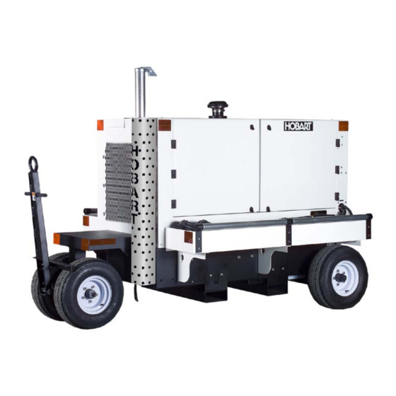
Description 1) General The basic generator set covered in this manual, manufactured by ITW GSE Group, Hobart Ground Systems is rated at 60 kVA and is designed to produce and deliver 115/200-volt, 400 Hz, 3-phase AC power to a parked aircraft or other load. Some generator models with the TR option also provide 28.5 volts DC for aircraft having those requirements. - Page 18 OM-2226 / Operation and Maintenance Manual 60CU20 / Series 500062 / 400 Hz. Generator Set 1. Fuel Filler Neck 8. Engine Air Intake 2. Operator’s Control Panel 9. Lift Off Access Doors 3. Output Cable Trays 10. CAC/Radiator End 4. 5 Wheel Assembly 11.
-
Page 19: Specifications
OM-2226 / Operation and Maintenance Manual 60CU20 / Series 500062 / 400 Hz. Generator Set 4) Specifications a) Physical Specifications Basic Unit Physical With Trailer (Fixed Mount) Length 74 in. (1880 mm) 101 in. (2570 mm) w/ tow bar up Width 67 in. - Page 20 OM-2226 / Operation and Maintenance Manual 60CU20 / Series 500062 / 400 Hz. Generator Set d) DC Output Specifications (with optional TR unit) Output Power Rating 17.1 kW Output Voltage 28.5 VDC Load Capacity (Continuous) 600 A Current Limiting Capability...
-
Page 21: Special Features
OM-2226 / Operation and Maintenance Manual 60CU20 / Series 500062 / 400 Hz. Generator Set 5) Special Features The generator set has special features that are described more fully under the assemblies in which they appear. a) Protective Monitoring The protective monitoring system receives signals from the fault sensing components in the generator output circuit and functions to cause the load to be disconnected from the generator if an abnormal condition of voltage, frequency, or load develops. - Page 22 OM-2226 / Operation and Maintenance Manual 60CU20 / Series 500062 / 400 Hz. Generator Set (2) Lubricity Additive Fuel Filter The fuel filter is a spin-on disposable type located on the inside near the engine’s fuel pump. The fuel filter’s primary function, other than remove contaminants from the fuel, is to automatically add a lubricity additive to the fuel.
- Page 23 OM-2226 / Operation and Maintenance Manual 60CU20 / Series 500062 / 400 Hz. Generator Set • Oil pressure shutdown system The oil pressure shutdown system consists of a factory supplied oil pressures switch. This switch is monitored by the microprocessor on the EIB (Engine Interface Board) PC Board, which will stop the engine if the oil pressure is under 12 PSI (82.7 kPA).
- Page 24 OM-2226 / Operation and Maintenance Manual 60CU20 / Series 500062 / 400 Hz. Generator Set The diesel engine air cleaner is so constructed that air enters through its cylindrical body, and then is filtered before being passed into the engine turbo-charger assembly. An air cleaner service indicator device is mounted on the air cleaner assembly to monitor the airflow into the air cleaner.
- Page 25 OM-2226 / Operation and Maintenance Manual 60CU20 / Series 500062 / 400 Hz. Generator Set 1. 28.5 VDC Contactor (optional) 7. 12 VDC Batteries (incase in housing) 2. Cummins QSB4.5 Engine 8. Generator 3. Air Filter Assembly 9. Turbo Exhaust Pipe / Exhaust Outlet 4.
- Page 26 OM-2226 / Operation and Maintenance Manual 60CU20 / Series 500062 / 400 Hz. Generator Set 1. 28.5 VDC Transformer-Rectifier (optional) 5. Engine Oil Level Check 2. Lubricity Additive Fuel Pre-Filter 6. Engine Air Intake Heater 3. Engine Electronic Fuse and Relay Panel 7.
-
Page 27: Control Box Assembly
OM-2226 / Operation and Maintenance Manual 60CU20 / Series 500062 / 400 Hz. Generator Set 8) Control Box Assembly The control box is a sheet metal enclosure that houses and provides mounting facilities for engine and generator controls, as well as, monitoring device and circuits. - Page 28 OM-2226 / Operation and Maintenance Manual 60CU20 / Series 500062 / 400 Hz. Generator Set 1. Engine Coolant Temperature Gauge (M24) 7. AC Generator Voltmeter (M2) 2. Running Time Meter (M4) 8. AC Generator Ammeter (M1) 3. Battery Voltmeter (M5) 9.
- Page 29 OM-2226 / Operation and Maintenance Manual 60CU20 / Series 500062 / 400 Hz. Generator Set • AC Voltmeter (M2) The voltmeter indicates the generator output voltage in each phase-to-neutral (A-N, B-N and C-N) or phase-to-phase (A-B, B-C and C-A) as selected by the METER SELECT switch. The voltmeter has a scale of 0 to 300 V.
- Page 30 OM-2226 / Operation and Maintenance Manual 60CU20 / Series 500062 / 400 Hz. Generator Set • ENGINE START switch (S24) The ENGINE START switch, when pressed, connects 12 VDC power to the starter solenoid coil, which actuates the solenoid switch to connect power to the engine starting motor. The...
- Page 31 OM-2226 / Operation and Maintenance Manual 60CU20 / Series 500062 / 400 Hz. Generator Set b) Control Box Interior Components 1. Control Box Wrapper 7. +5, -12 VDC Power Supply (PS1) 2. Engine Specific PC Board [ESB] (A1) 8. Circuit Breaker Support Bracket 3.
- Page 32 OM-2226 / Operation and Maintenance Manual 60CU20 / Series 500062 / 400 Hz. Generator Set Figure 7: Engine Specific PC Board (2) Engine Specific PC Board [ESB] (A1) The ESB is the primary interface between the control system and the engine’s electronic control module.
- Page 33 OM-2226 / Operation and Maintenance Manual 60CU20 / Series 500062 / 400 Hz. Generator Set Figure 8: Engine Interface PC Board (4) Digital Control PC Board [CTL] (A3) The digital control PC board is the center for all communications throughout the entire control system.
- Page 34 OM-2226 / Operation and Maintenance Manual 60CU20 / Series 500062 / 400 Hz. Generator Set Figure 9: Digital Control PC Board (5) Voltage regulator PC board [REG] (A4) This voltage regulator PC board is designed to provide voltage regulation for a three-phase, four- wire, 115/200-volt, 400-Hz brushless alternator.
- Page 35 OM-2226 / Operation and Maintenance Manual 60CU20 / Series 500062 / 400 Hz. Generator Set Figure 10: Voltage Regulator PC Board • When a load is removed from the alternator, the alternator voltage rises. The rectified three- phase voltage-sensing signal increases, causing this signal to be higher than the reference signal.
- Page 36 OM-2226 / Operation and Maintenance Manual 60CU20 / Series 500062 / 400 Hz. Generator Set Regulated-diagnostic switch (located on the REG) When the REGULATED/DIAGNOSTIC switch is in the REGULATED (down) position, the generator output voltage is regulated by the PC board for 115/200 VAC output to an aircraft.
- Page 37 OM-2226 / Operation and Maintenance Manual 60CU20 / Series 500062 / 400 Hz. Generator Set (7) +5, -12 VDC Power Source (PS1) Supplies the internal power distribution of +5 VDC and –12 VDC into the control system. Figure 12: Control System Power Source...
-
Page 38: Power Module Panel Assembly
OM-2226 / Operation and Maintenance Manual 60CU20 / Series 500062 / 400 Hz. Generator Set 9) Power Module Panel Assembly The power module panel assembly sometimes referred to as the contactor panel, is located at the rear of the machine under the control box. The panel assembly provides a means of connecting and disconnecting generator output to and from the aircraft. - Page 39 OM-2226 / Operation and Maintenance Manual 60CU20 / Series 500062 / 400 Hz. Generator Set Output # 2 Contactor Output # 1 Contactor, Current Location Transformers and Cabling Hobart Generator Generator Lead Connection Exciter End Point and Neutral Figure 13: Output Power Module Components...
-
Page 40: Cold Weather Start System
OM-2226 / Operation and Maintenance Manual 60CU20 / Series 500062 / 400 Hz. Generator Set 10) Cold Weather Starting System (BH1) The intake air heater, located on the intake manifold, is used for starting the engine at very cold temperatures and reduces the white smoke associated with a cold start. This cold weather starting system is fully automatic once engaged by the operator (Chapter 1, Section 3). -
Page 41: Transformer-Rectifier (T-R) Assembly
OM-2226 / Operation and Maintenance Manual 60CU20 / Series 500062 / 400 Hz. Generator Set 11) Transformer-Rectifier (T-R) Assembly The T-R provides a regulated output voltage of 28.5V DC. Input power is provided to the DC components from the 115/200 volt, 400 Hz generator set, through an input contactor. The output contactor provides DC power to the load. - Page 42 OM-2226 / Operation and Maintenance Manual 60CU20 / Series 500062 / 400 Hz. Generator Set 1. Transformer Assembly (T401) 5. DC Inductor / Filter Assembly (L401) 2. Heat Sink / Diode Assembly (CR402-CR407) 6. Pre-Load Resistors (R402-R404) 3. Input Contactor (K401) 7.
-
Page 43: Preparation For Use, Storage Or Shipping
OM-2226 / Operation and Maintenance Manual 60CU20 / Series 500062 / 400 Hz. Generator Set Section 2 Preparation for Use, Storage, or Shipping 1) Preparation for Use a) Inspection/Check Inspect the unit thoroughly prior to operation. (1) Remove blocking, banding, ties, and other securing material. - Page 44 OM-2226 / Operation and Maintenance Manual 60CU20 / Series 500062 / 400 Hz. Generator Set (8) Check the engine lubricating oil level. The oil gauge rod has H high mark and L low-level marks to indicate the operating lubrication oil supply. Oil level should be kept as near the high mark as possible, without going over it.
- Page 45 OM-2226 / Operation and Maintenance Manual 60CU20 / Series 500062 / 400 Hz. Generator Set b) Installing Three-Phase AC Output Cables The generator set may be shipped without aircraft cables. The output cables connect to the load contactors, which are located on the power module assembly (left side of the unit beneath the engine control panel).
- Page 46 OM-2226 / Operation and Maintenance Manual 60CU20 / Series 500062 / 400 Hz. Generator Set DC Cable and Clamp Figure 3 DC Output Cables Output Cable Connections Figure 4 May 2, 2013 Chapter 1-2 Page 4...
-
Page 47: Preparation For Storage
(2) The unit should be stored in a building which is dry and which may be heated during winter months. (3) Moisture-absorbing chemicals (Hobart Part No. 76A1354-001) are available for use where excessive dampness is a problem; however, the unit must be completely packaged and sealed if moisture-absorbing chemicals are to be effective. -
Page 48: Preparation For Shipment
Place containers of moisture- absorbing chemicals (Hobart Part No. 76A-1354-001) in the unit before packaging. The unit may be stored for long periods with no special preparation if it is possible to operate the engine once each week. -
Page 49: Operation
OM-2226 / Operation and Maintenance Manual 60CU20 / Series 500062 / 400 Hz. Generator Set Section 3 Operation 1) General This section contains information and instructions for the safe and efficient operation of the equipment. Operating instructions are presented in step-by-step sequence of procedures to be followed in supplying 400-Hz power. - Page 50 OM-2226 / Operation and Maintenance Manual 60CU20 / Series 500062 / 400 Hz. Generator Set 1. Engine Coolant Temperature Gauge (M24) 7. AC Generator Voltmeter (M2) 2. Running Time Meter (M4) 8. AC Generator Ammeter (M1) 3. Battery Voltmeter (M5) 9.
- Page 51 OM-2226 / Operation and Maintenance Manual 60CU20 / Series 500062 / 400 Hz. Generator Set b) Normal Engine Starting Procedures Engine starting procedures are outlined below. The engine’s operating controls and monitoring instruments are illustrated in Figure 1. CAUTION Refer to operating instructions in the engine manufacturer’s operation manual, when starting engine for the first time.
- Page 52 OM-2226 / Operation and Maintenance Manual 60CU20 / Series 500062 / 400 Hz. Generator Set CAUTION To eliminate the possibility of wet stacking (See Appendix A), DO NOT allow the engine to idle for long periods. c) Failed Starting Procedure...
- Page 53 OM-2226 / Operation and Maintenance Manual 60CU20 / Series 500062 / 400 Hz. Generator Set WARNING NEVER disconnect the output cable while power is being delivered. Output contactors must be open prior to removal of the cable from the aircraft.
-
Page 54: Dc Operation Procedure
OM-2226 / Operation and Maintenance Manual 60CU20 / Series 500062 / 400 Hz. Generator Set 3) DC Operating Procedure (optional) This section describes the operation of the optional DC unit. The DC output voltage value, which is controlled by a potentiometer on the Transformer-Rectifier Board (TRB), need only be set once. The voltage level will remain the same for all future operations, even when the unit is shut down or the battery is disconnected. -
Page 55: Maintenance Inspection/Check
OM-2226 / Operation and Maintenance Manual 60CU20 / Series 500062 / 400 Hz. Generator Set Chapter 2 Service and Troubleshooting Section 1 Maintenance Inspection/Check 1) General To make certain the generator set is always ready for operation, it must be inspected and maintained regularly and systematically so that defects may be discovered and corrected before they result in serious damage to components, or failure of the equipment. - Page 56 OM-2226 / Operation and Maintenance Manual 60CU20 / Series 500062 / 400 Hz. Generator Set Hourly Interval 50-150 1000 1500 2000 Calendar Interval Once Daily 3 Mo. 6 Mo. 1 Yr. 1.5 Yr. 2 Yr. Symbol Engine Change Air Cleaner Cartridge...
-
Page 57: Inspection/Check
OM-2226 / Operation and Maintenance Manual 60CU20 / Series 500062 / 400 Hz. Generator Set Hourly Interval 50-150 1000 1500 2000 Calendar Interval Once Daily 3 Mo. 6 Mo. 1 Yr. 1.5 Yr. 2 Yr. Symbol Engine (continued) Flush and Change Coolant Check Fan Mounting Spring &... -
Page 58: Engine
OM-2226 / Operation and Maintenance Manual 60CU20 / Series 500062 / 400 Hz. Generator Set b) “AR” Checks and Operations (As Required) (1) Engine Change Air Cleaner Replace the air filter when the fault code meter shows the “air” code. These filters should not be washed because washing breaks down the material inside the filters. -
Page 59: Check Crankcase Oil Level
OM-2226 / Operation and Maintenance Manual 60CU20 / Series 500062 / 400 Hz. Generator Set d) “A” Checks and Operations (10 Hours or Daily) (1) Engine Check Crankcase Oil Level CAUTION DO NOT overfill. DO NOT operate the engine with oil level below the lower bar or above the upper bar on the dipstick. -
Page 60: Check Exhaust System
OM-2226 / Operation and Maintenance Manual 60CU20 / Series 500062 / 400 Hz. Generator Set Fuel Pre-Filter and Drain Figure 2 Water Drain Check Fault Code Meter At each daily start-up, observe the fault code meter on the control panel. If the display shows “air”, change the air filter. -
Page 61: Charge-Air-Cooler (Cac) And Piping
OM-2226 / Operation and Maintenance Manual 60CU20 / Series 500062 / 400 Hz. Generator Set (3) Electrical (400 Hz System) Check Output Cables and Connector Check the output cable and plug connection for damaged insulation and contacts each time the connector is detached from the aircraft. -
Page 62: Check Fuel Pump
OM-2226 / Operation and Maintenance Manual 60CU20 / Series 500062 / 400 Hz. Generator Set Check Radiator Core and Hoses Inspect the radiator core for dirt and debris blocking the fins. Clean as necessary. Check for cracks, holes, or other damage. -
Page 63: Check Fan Hub And Drive Pulley
OM-2226 / Operation and Maintenance Manual 60CU20 / Series 500062 / 400 Hz. Generator Set (3) Electrical (400 Hz System) Protective Monitoring Circuits Check operation of all protective monitoring circuits to make certain they will function if a fault should occurs in the output circuit. Procedures for testing these circuits are contained in the Adjustment/Test section of this manual. -
Page 64: Steam Clean Engine
OM-2226 / Operation and Maintenance Manual 60CU20 / Series 500062 / 400 Hz. Generator Set h) “E” Checks and Operations (1500 Hours or 1.5 Year) (1) Engine Steam Clean Engine There are several reasons why the engine exterior should be kept clean. Dirt on the outside will enter fuel and oil filter cases and rocker housings when covers are removed, unless dirt is removed first. -
Page 65: Check Vibration Damper
OM-2226 / Operation and Maintenance Manual 60CU20 / Series 500062 / 400 Hz. Generator Set “F” Checks and Operations (2000 Hours or 2 Years) (1) Engine Check Vibration Damper. 1. Fan Pulley 5. Alternator 2. Vibration Damper 6. Belt Tensioner 3. - Page 66 OM-2226 / Operation and Maintenance Manual 60CU20 / Series 500062 / 400 Hz. Generator Set Seasonal Maintenance Checks Spring/Fall (Engine) (1) Check Fan Mounting Check fan to be sure it is securely mounted. Check for fan wobble and/or broken/cracked blades.
- Page 67 OM-2226 / Operation and Maintenance Manual 60CU20 / Series 500062 / 400 Hz. Generator Set k) Lamps Circuit breakers, and Fuses (1) Check all lamps daily (2) Check circuit breakers and fuses as required. (3) The lamp chart lists all lamps with their location and identifying trade number in table below.
- Page 68 OM-2226 / Operation and Maintenance Manual 60CU20 / Series 500062 / 400 Hz. Generator Set Lamp (Bulb) as per Lamp Light Identification Location Industry Trade Number or Description Engine Start Indicator Switch Panel 1815 Engine Stop Indicator Switch Panel 1815 No.
-
Page 69: Maintenance Procedures
OM-2226 / Operation and Maintenance Manual 60CU20 / Series 500062 / 400 Hz. Generator Set Section 2 Maintenance Procedures 1) General A suggested maintenance schedule is provided in Section 1 of this Servicing Chapter. Each step of the schedule is also covered in general in Section 1. This Section covers maintenance in more detail, where necessary. -
Page 70: Engine Lubrication
OM-2226 / Operation and Maintenance Manual 60CU20 / Series 500062 / 400 Hz. Generator Set 2) Engine Lubrication a) General Proper lubrication is one of the most important steps in good maintenance procedure. Proper lubrication means the use of correct lubricants and adherence to a proper time schedule. Lubrication points, frequency of lubrication, and recommended lubricants are indicated in Figures 1 and 2. - Page 71 OM-2226 / Operation and Maintenance Manual 60CU20 / Series 500062 / 400 Hz. Generator Set c) Changing engine oil Change the oil once after the first 50 - 150 hours of use and then every 500 hours of engine operation thereafter.
- Page 72 OM-2226 / Operation and Maintenance Manual 60CU20 / Series 500062 / 400 Hz. Generator Set Change oil as follows: (1) Provide an open container for catching the old oil below the oil drain plug. Container capacity must be greater than 30 quarts (28.4 liters).
- Page 73 OM-2226 / Operation and Maintenance Manual 60CU20 / Series 500062 / 400 Hz. Generator Set Symbol Name Specification Notes Grease, General Purpose MIL-G-3545 Excludes those of sodium or soda soap thickness. Lubricants Chart e) Engine Accessories Lubrication (1) Alternator Most alternators contain sealed bearings and require no periodic lubrication, however, check to make certain there are no lubrication points on your particular alternator.
-
Page 74: Servicing The Air Cleaner
OM-2226 / Operation and Maintenance Manual 60CU20 / Series 500062 / 400 Hz. Generator Set 3) Servicing the Air Cleaner A definite time schedule for cleaning or changing the air cleaner cannot be determined because of varying operating conditions. Unfasten the three metal latches on the end of the air cleaner housing to access the air cleaner filter. -
Page 75: Engine Fuel
OM-2226 / Operation and Maintenance Manual 60CU20 / Series 500062 / 400 Hz. Generator Set c) Disposal Normal trash pick-up is should be acceptable. NEVER burn the air filter for disposal. 4) Engine Fuel a) How to select Fuel—Quality The quality of fuel oil used in the diesel engine is a major factor in engine performance and life. Fuel oil must be clean, completely distilled, stable and non-corrosive. -
Page 76: Engine Fuel System
OM-2226 / Operation and Maintenance Manual 60CU20 / Series 500062 / 400 Hz. Generator Set 5) Engine Fuel System The fuel system consists of five primary components: fuel tank, lubricity filter, primary fuel filter, fuel lift pump, and the fuel return line. The following are maintenance procedures for each of these items. - Page 77 OM-2226 / Operation and Maintenance Manual 60CU20 / Series 500062 / 400 Hz. Generator Set To change the lubricity filter: CAUTION When installing new element, do not over tighten it; mechanical tools may distort or crack filter head. (1) Place a pan underneath the fuel filter to catch spilled fuel.
- Page 78 OM-2226 / Operation and Maintenance Manual 60CU20 / Series 500062 / 400 Hz. Generator Set The fuel filter must be change after every 500 hours of operation. To change the fuel filter: (1) Shut off fuel valve. (2) Place a pan underneath the fuel filter to catch spilled fuel.
-
Page 79: Engine Cooling System
OM-2226 / Operation and Maintenance Manual 60CU20 / Series 500062 / 400 Hz. Generator Set 6) Engine Cooling System a) General Cooling system service requires more than maintaining the proper coolant level in the radiator and protecting the system against freezing. Water should by clean and free of any corrosive chemicals such as chloride, sulfate, and acids. - Page 80 OM-2226 / Operation and Maintenance Manual 60CU20 / Series 500062 / 400 Hz. Generator Set CAUTION Never use soluble oil in the cooling system. (1) General A permanent type antifreeze is recommended for use in the cooling system. CAUTION 1. DO NOT use methanol or alcohol as antifreeze.
- Page 81 OM-2226 / Operation and Maintenance Manual 60CU20 / Series 500062 / 400 Hz. Generator Set Cleaning the Radiator Core Blow out accumulated dirt from the radiator core air passages, using water. Bent or clogged radiator fins often cause engine overheating. When straightening bent fins, be careful not to damage the tubes or to break the bond between fins and tubes.
-
Page 82: Drive Belt
OM-2226 / Operation and Maintenance Manual 60CU20 / Series 500062 / 400 Hz. Generator Set 7) Engine Drive Belt a) General The engine cooling fan, alternator, and water pumps are driven by one serpentine belt, which must be replaced if worn or damaged. -
Page 83: Adjustments / Tests
OM-2226 / Operation and Maintenance Manual 60CU20 / Series 500062 / 400 Hz. Generator Set Section 3 Adjustment/Test 1) General These adjustments and test procedures are applicable to testing and adjusting the generator set after major repair, major parts replacements, or overhaul. - Page 84 OM-2226 / Operation and Maintenance Manual 60CU20 / Series 500062 / 400 Hz. Generator Set 1. Engine Coolant Temperature Gauge (M24) 7. AC Generator Voltmeter (M2) 2. Running Time Meter (M4) 8. AC Generator Ammeter (M1) 3. Battery Voltmeter (M5) 9.
- Page 85 OM-2226 / Operation and Maintenance Manual 60CU20 / Series 500062 / 400 Hz. Generator Set b) Operational Test Procedures (1) Start the engine in accordance with instructions in Section 1-3. (2) Check operation of engine instruments; ammeter, coolant temperature indicator, oil pressure gage and hour meter.
- Page 86 OM-2226 / Operation and Maintenance Manual 60CU20 / Series 500062 / 400 Hz. Generator Set Figure 2: Control Box Interior Components May 2, 2013 Chapter 2-3 Page 4...
- Page 87 OM-2226 / Operation and Maintenance Manual 60CU20 / Series 500062 / 400 Hz. Generator Set c) Testing the No. 1 Output Circuit (1) Place EF Bypass switch in “BYPASS / OFF” position turn the EF signal “ON” on the load bank.
- Page 88 OM-2226 / Operation and Maintenance Manual 60CU20 / Series 500062 / 400 Hz. Generator Set (5) Place the No. 1 EF bypass switch to “BYPASS / OFF” position. The No. 1 load contactor should open at once and the yellow indicating light within the No. 1 load contactor push button switch should go off and the fault code display should also read “EF 1”, indicating a EF warning.
- Page 89 OM-2226 / Operation and Maintenance Manual 60CU20 / Series 500062 / 400 Hz. Generator Set (11) In EF bypass mode, apply 1/3 to 1/2 load at the load bank and allow the unit to run for 15 to 30 minutes. Observe operation of all monitoring instruments.
- Page 90 OM-2226 / Operation and Maintenance Manual 60CU20 / Series 500062 / 400 Hz. Generator Set In any LINE-TO-LINE position, voltmeter reading should be 200 volts when the LED under the voltmeter indicates two of the phases being checked. (4) Check accuracy of frequency meter Connect a master frequency meter of known accuracy to the terminals of the frequency meter.
- Page 91 OM-2226 / Operation and Maintenance Manual 60CU20 / Series 500062 / 400 Hz. Generator Set If the under voltage circuit performs satisfactorily, return unit to normal operation by adjusting output voltage coarse adjustment potentiometer for normal output voltage, pressing the “TEST/REST”...
- Page 92 OM-2226 / Operation and Maintenance Manual 60CU20 / Series 500062 / 400 Hz. Generator Set (8) Check over-frequency circuit and fault code display. At some frequency value 420 Hz to 440 Hz, after 5 seconds, the over frequency sensing circuit should signal the over-frequency circuit protective monitor to OPEN the load contactor and display “70.22”...
- Page 93 OM-2226 / Operation and Maintenance Manual 60CU20 / Series 500062 / 400 Hz. Generator Set Figure 6: Engine Interface PC Board (4) The fault code will flash in the following sequence: First, a “Check Engine” (yellow) lamp will flash. There will be a short 1- or 2-second pause after which the number of the recorded fault code will flash in the “Engine Stop”...
-
Page 94: Generator Set Adjustments
OM-2226 / Operation and Maintenance Manual 60CU20 / Series 500062 / 400 Hz. Generator Set g) Re-checking the entire unit after testing (1) With the engine running at normal rated speed, check the entire unit for vibration and for any parts that may have become loosened during the above checks. - Page 95 OM-2226 / Operation and Maintenance Manual 60CU20 / Series 500062 / 400 Hz. Generator Set Figure 7: Voltage Regulator PC Board (1) Output Voltage Adjustment Adjust Voltage Control The output voltage, at which the generator is regulated, is adjustable by the fine voltage adjustment potentiometer.
- Page 96 OM-2226 / Operation and Maintenance Manual 60CU20 / Series 500062 / 400 Hz. Generator Set Adjust Line-Drop Compensation Adjustment of line-drop compensation is made with the line-drop compensation potentiometer. Turning the potentiometer knob clockwise increases the magnitude of the compensation, and turning the potentiometer knob counterclockwise decreases the magnitude (A graduated nameplate for specified cable lengths is included for quick reference.).
-
Page 97: Generator And Exciter Test
OM-2226 / Operation and Maintenance Manual 60CU20 / Series 500062 / 400 Hz. Generator Set d) Engine Accessories Adjustment Alternator and fan belt adjustment: Refer to Section 2-1 and engine manufacturer manual. 4) Generator and Exciter Test The generator fields and exciter stator may be tested with a Kelvin bridge. This is a double-bridge type instrument required for the very low resistance’s encountered in this test. -
Page 98: Diode Test
OM-2226 / Operation and Maintenance Manual 60CU20 / Series 500062 / 400 Hz. Generator Set 5) Diode Test Test values for diodes are not given here because they could be misleading. Test values may vary even between diodes of the same part number, rating, and manufacturer. General instructions for testing diodes are as follows: a) Disconnect exciter windings from diode lead(s). - Page 99 OM-2226 / Operation and Maintenance Manual 60CU20 / Series 500062 / 400 Hz. Generator Set (3) Current Limiting / Soft Starting Control Press the “STARTNG CURRENT” push button to activate the current limiting and set the limit to 1500 A.
-
Page 100: Adjusting The Transformer-Rectifier
OM-2226 / Operation and Maintenance Manual 60CU20 / Series 500062 / 400 Hz. Generator Set The contactor should open in 10 seconds. The fault code meter will read “70.30” Discontinue power delivery and let the cables cool for 2-3 minutes. -
Page 101: Troubleshooting Procedures
OM-2226 / Operation and Maintenance Manual 60CU20 / Series 500062 / 400 Hz. Generator Set Section 4 Troubleshooting Procedures 1) General The Troubleshooting Chart and Fault Code Chart located in this section cover the common faults and malfunctions that you may find during operation or maintenance of this equipment. The charts may not list all faults and malfunctions that may occur. -
Page 102: Normal Operation
OM-2226 / Operation and Maintenance Manual 60CU20 / Series 500062 / 400 Hz. Generator Set 4) Normal Operation The system specifications, which are listed in Section 1-1, provide useful information when troubleshooting abnormal operation. In particular, the Protective System Specifications and the Normal Operating Characteristics provide information about how the generator set should be operating. -
Page 103: Gpu Control Monitoring
OM-2226 / Operation and Maintenance Manual 60CU20 / Series 500062 / 400 Hz. Generator Set 9) GPU Control Monitoring The GPU control system performs complete diagnostic testing and continuous monitoring of all critical circuits and operating electrical values. If the control system senses a problem with one of the circuits or if any of the electrical values exceeds its safe operating limit, the control system will shut the GPU down, or may allow the GPU to continue operation depending on the severity of the condition. - Page 104 OM-2226 / Operation and Maintenance Manual 60CU20 / Series 500062 / 400 Hz. Generator Set (3) Engine Idle Mode When the engine has been started, the engine will begin in the idle mode. The ENGINE START push-button will flash indicating the engine is in the idle mode.
- Page 105 OM-2226 / Operation and Maintenance Manual 60CU20 / Series 500062 / 400 Hz. Generator Set (1) Warning Warning faults have no effect on the operation of the GPU. An example is an intake air restriction fault due to a dirty filter. Although the GPU continues to operate, the fault appears on the fault code display.
- Page 106 OM-2226 / Operation and Maintenance Manual 60CU20 / Series 500062 / 400 Hz. Generator Set Command Fault 70.67 Fault Codes Fault Meter Display Figure 1 d) Operation Monitoring While applying power to an aircraft, the GPU continually monitors all critical circuits and operating electrical values.
- Page 107 OM-2226 / Operation and Maintenance Manual 60CU20 / Series 500062 / 400 Hz. Generator Set Record Designator Record Number - 1 21 Fault Record Number “121” Fault Meter Display (Fault Record Number) Figure 2 (4) Release the TEST/RESET pushbutton. The display alternates between the fault record number (See Figure 2) and the fault code (See Figure 1).
- Page 108 OM-2226 / Operation and Maintenance Manual 60CU20 / Series 500062 / 400 Hz. Generator Set 1. Engine Coolant Temperature Gauge (M24) 7. AC Generator Voltmeter (M2) 2. Running Time Meter (M4) 8. AC Generator Ammeter (M1) 3. Battery Voltmeter (M5) 9.
- Page 109 OM-2226 / Operation and Maintenance Manual 60CU20 / Series 500062 / 400 Hz. Generator Set Control Box Interior Components Figure 4 Printed Circuit Board Name Abbreviation Engine-Specific board Engine Interface board Voltage Regulator board Digital Control board Transformer-Rectifier board May 2, 2013...
-
Page 110: Troubleshooting Charts
OM-2226 / Operation and Maintenance Manual 60CU20 / Series 500062 / 400 Hz. Generator Set 10) Troubleshooting Charts Engine Controls Trouble, Symptom, Probable Cause Test, Check, and/or Remedy Condition • Make sure the Emergency Stop switch is pulled out. 1. The engine will not a. - Page 111 OM-2226 / Operation and Maintenance Manual 60CU20 / Series 500062 / 400 Hz. Generator Set Engine Controls (continued) Trouble, Probable Cause Test, Check, and/or Remedy Symptom, Condition 3. Engine will not a. Low battery output Check the battery and recharge or replace start.
- Page 112 OM-2226 / Operation and Maintenance Manual 60CU20 / Series 500062 / 400 Hz. Generator Set Engine Controls (continued) Trouble, Symptom, Probable Cause Test, Check, and/or Remedy Condition 8. Engine either goes a. Low fuel was detected or the Add No. 2 diesel fuel.
-
Page 113: Generator Excitation Circuits
OM-2226 / Operation and Maintenance Manual 60CU20 / Series 500062 / 400 Hz. Generator Set Generator Excitation Circuits Trouble, Symptom, Probable Cause Test, Check, and/or Remedy Condition 1. No (or low) a. Defective generator or On Voltage Regulator (REG) board (A4), place the... -
Page 114: Load Contactor Operating Circuits
OM-2226 / Operation and Maintenance Manual 60CU20 / Series 500062 / 400 Hz. Generator Set Load Contactor Operating Circuits Output 1: Contactor K1, Pushbutton switch S75 Output 2: Contactor K201, Pushbutton switch S275 Trouble, Symptom, Condition Probable Cause Test, Check, and/or Remedy 1. - Page 115 OM-2226 / Operation and Maintenance Manual 60CU20 / Series 500062 / 400 Hz. Generator Set Load Contactor Operating Circuit (Continued) Trouble, Symptom, Condition Probable Cause Test, Check, and/or Remedy 2. Load contactor closes when a. The plug interlock EF circuit on...
-
Page 116: Protective Circuit
OM-2226 / Operation and Maintenance Manual 60CU20 / Series 500062 / 400 Hz. Generator Set Protective Circuit NOTE: Protective monitoring is not completely functional until the load contactor is CLOSED. Since it is not advisable to vary voltages for test purposes while delivering power to an aircraft, the GPU should be connected to a load bank for trouble shooting protective circuits. - Page 117 OM-2226 / Operation and Maintenance Manual 60CU20 / Series 500062 / 400 Hz. Generator Set Protective Circuit (continued) Trouble, Symptom, Probable Cause Test, Check, and/or Remedy Condition 3. Load contactor opens a. Frequency adjust Set frequency adjust switch on the ESB board to during power delivery.
-
Page 118: Generator
OM-2226 / Operation and Maintenance Manual 60CU20 / Series 500062 / 400 Hz. Generator Set Generator Trouble, Symptom, Probable Cause Test, Check, and/or Remedy Condition 1. No (or low) voltage output a. Shorted diode in exciter Check diodes in accordance with Section rectifier (CR2) 2-3. -
Page 119: T-R Controls And Components
OM-2226 / Operation and Maintenance Manual 60CU20 / Series 500062 / 400 Hz. Generator Set T-R Controls and Components Trouble, Symptom, Probable Cause Test, Check, and/or Remedy Condition 1. Input AC and Output DC a. Defective push button switch At rated speed, measure the voltage across contactor will not close the switch. - Page 120 OM-2226 / Operation and Maintenance Manual 60CU20 / Series 500062 / 400 Hz. Generator Set T-R Controls and Components (continued) Trouble, Symptom, Condition Probable Cause Test, Check, and/or Remedy 2. (continued) e. Interlock signal not being Be sure the output cable is properly...
- Page 121 OM-2226 / Operation and Maintenance Manual 60CU20 / Series 500062 / 400 Hz. Generator Set Troubleshooting Tables a) GPU Commands GPU Commands Name Description code 00. _ _ Invalid Command 01. _ _ ENGINE SELF-TEST CMD All boards test the communication between each other.
- Page 122 OM-2226 / Operation and Maintenance Manual 60CU20 / Series 500062 / 400 Hz. Generator Set b) Faults Faults Fault Name Possible Cause(s) Corrective Action code Check for obstructions. Air filter is obstructed or dirty. EIB AIR RESTRICTION FAULT Change air filter cartridge or Bad air restriction indicator air restriction indicator.
- Page 123 OM-2226 / Operation and Maintenance Manual 60CU20 / Series 500062 / 400 Hz. Generator Set Faults Fault Name Possible Cause(s) Corrective Action code Defective output contactor Replace output contactor. _ _.24 REG CONTACTOR1 FAULT Defective REG board Replace REG board.
- Page 124 OM-2226 / Operation and Maintenance Manual 60CU20 / Series 500062 / 400 Hz. Generator Set Faults Fault Name Possible Cause(s) Corrective Action code Check for ID R2 on TB1. The REG board cannot find the Check for broken wire on ID R2 on _ _.48...
-
Page 125: Overhaul / Major Repair
OM-2226 / Operation and Maintenance Manual 60CU20 / Series 500062 / 400 Hz. Generator Set Chapter 3 Overhaul/Major Repair Section 1 Exciter Armature 1) General This section provides information and instructions for removal and installation of the exciter armature used on this generator set. Through design improvements, the exciter and rear main bearing can be removed without removing the generator from the generator set. -
Page 126: Exciter Armature
OM-2226 / Operation and Maintenance Manual 60CU20 / Series 500062 / 400 Hz. Generator Set 3. Diode Mounting Plate 1. Exciter Core Flange 2. Exciter Core Lamination 4. Silicon Diode Exciter Armature Figure 2 The exciter armature is mounted on the rear portion of the main generator armature shaft, which extends rearward beyond the rear generator bearing into the exciter housing (See Figure 1). -
Page 127: General
OM-2226 / Operation and Maintenance Manual 60CU20 / Series 500062 / 400 Hz. Generator Set The exciter armature is mounted on the main generator armature shaft with a 3/8-inch square machine key that is held in place by a key retainer, and an M12-1.75 hex head cap screw in the center of the diode mounting plate. - Page 128 OM-2226 / Operation and Maintenance Manual 60CU20 / Series 500062 / 400 Hz. Generator Set (4) Disconnect the two rectifier-to-generator field leads, which are attached to the rectifier mounting plate with ring terminals. (5) Take EXERCISE CARE to prevent damage to leads. Remove kinks in the two generator leads as much as possible before starting removal operation (The exciter armature will be sliding over these leads.).
- Page 129 OM-2226 / Operation and Maintenance Manual 60CU20 / Series 500062 / 400 Hz. Generator Set WARNING To prevent personal injury, keep fingers and hands clear of generator assembly until the armature is block into place to prevent rotation. Attempt to loosen exciter armature on shaft by rotating it slightly back and forth. If armature cannot be loosened by hand, use two M10-1.5 hex-head bolts as shown in Figure 4 to force...
-
Page 130: Exciter Armature Installation
OM-2226 / Operation and Maintenance Manual 60CU20 / Series 500062 / 400 Hz. Generator Set CAUTION Pay close attention to field leads while pulling exciter armature from shaft. Make CERTAIN that the leads stay in the 1/2" keyway. One mechanic should watch them constantly while another operates the puller. - Page 131 OM-2226 / Operation and Maintenance Manual 60CU20 / Series 500062 / 400 Hz. Generator Set b) Exciter Armature Installation (1) If the exciter armature-to-generator shaft fit is such that the exciter armature may be pushed on by hand, push it on very slowly while another mechanic carefully watches and pulls field leads through hole in the exciter armature diode mounting plate.
- Page 132 OM-2226 / Operation and Maintenance Manual 60CU20 / Series 500062 / 400 Hz. Generator Set (3) Install the Machine Key Clean the machine key thoroughly. All mounting surfaces must be free of rust, corrosion, oil, grease, etc. Apply LOCQUIC primer, No. 47-56 grade T to SIDES of machine key. Do not over prime. A thin film is best.
-
Page 133: Dual Bearing Flexible Coupling
Hobart Ground Systems as Part Number 288481. This assembly is illustrated in Figure 1. The primary function of this assembly is to couple a Hobart 2000 RPM Generator to a Diesel engine. The flexible coupling assembly compensates for slight misalignment between the engine and the generator, due to manufacturing tolerances. - Page 134 OM-2226 / Operation and Maintenance Manual 60CU20 / Series 500062 / 400 Hz. Generator Set Access to Coupling Bolts (for removal or installation) Figure 2 b) Remove Coupling Assembly WARNING To prevent personal injury, keep fingers and hands clear of generator assembly until the armature is block into place to prevent rotation.
- Page 135 OM-2226 / Operation and Maintenance Manual 60CU20 / Series 500062 / 400 Hz. Generator Set Check the shaft for any damage or deformation where the coupling was mounted on it. Check rubber bushing alignment to make sure that the dimension illustrated in Figure 4 is maintained.
-
Page 136: Coupling Service
Bushing Kit A bushing kit is available from the Hobart Ground Systems for replacing the rubber bushing only in the coupling assembly. However, it should be noted that the finished coupling assembly must be balanced to 1/2 inch-ounce (360 mg-m) minimum. -
Page 137: Coupling Installation
OM-2226 / Operation and Maintenance Manual 60CU20 / Series 500062 / 400 Hz. Generator Set (3) Shake the container of lubricant (supplied with kit) vigorously and poor it into a small shallow dish. (4) Roll a bushing in the lubricant to coat it thoroughly. Press it into a socket (from the chamfered end) to the dimension shown in Figure 4. -
Page 138: Reassemble Engine And Generator
OM-2226 / Operation and Maintenance Manual 60CU20 / Series 500062 / 400 Hz. Generator Set (5) Slide the generator armature as far as it will go toward the fan housing. Block the armature to maintain this forward position throughout the installation procedure. Block the armature with a wooden block or wedge, being careful not to damage any components of the armature or exciter. -
Page 139: Run-In And Periodic Check
OM-2226 / Operation and Maintenance Manual 60CU20 / Series 500062 / 400 Hz. Generator Set CAUTION Remove all armature blocks, otherwise, damage to the armature could result. 6) Run-in and Periodic Check a) Mount the engine-generator assembly in a suitable test area and operate it for a 2-hour run-in. - Page 140 OM-2226 / Operation and Maintenance Manual 60CU20 / Series 500062 / 400 Hz. Generator Set Bushing Installation Figure 4 May 2, 2013 Chapter 3-2 Page 8...
- Page 141 OM-2226 / Operation and Maintenance Manual 60CU20 / Series 500062 / 400 Hz. Generator Set Assembly Procedure Figure 5 Measure from mounting face to adapter ring. Figure 6 May 2, 2013 Chapter 3-2 Page 9...
- Page 142 OM-2226 / Operation and Maintenance Manual 60CU20 / Series 500062 / 400 Hz. Generator Set Measuring From Mounting Face To Bushing Figure 7 May 2, 2013 Chapter 3-2 Page 10...
-
Page 143: Generator Assembly
OM-2226 / Operation and Maintenance Manual 60CU20 / Series 500062 / 400 Hz. Generator Set Section 3 Generator Assembly 1) General This section provides information and instructions for removal and installation of the generator set. 2) Generator Assembly Removal a) Procedure for Gaining Access to the Generator... -
Page 144: Generator Assembly Installation
OM-2226 / Operation and Maintenance Manual 60CU20 / Series 500062 / 400 Hz. Generator Set Generator Lifting Arrangement Figure 1 3) Generator Assembly Installation Installation of a generator assembly is essentially a reversal of the procedure for removal of the generator assembly: the re-mounting of the generator assembly to the frame of the generator set, and the remounting of the assemblies that were removed to gain access to the generator assembly. -
Page 145: Introduction
1) General The Illustrated Parts List identifies, describes, and illustrates main assemblies, subassemblies, and detail parts of an Engine-Generator Set manufactured by ITW GSE Group, Hobart Ground Systems. 2) Purpose The purpose of this list is to provide parts identification and descriptive information to maintenance and provisioning personnel for use in provisioning, requisitioning, purchasing, storing, and issuing of spare parts. - Page 146 60CU20 / Series 500062 / 400 Hz. Generator Set (2) FACTORY PART NUMBER Column All part numbers appearing in this column are Hobart numbers. In all instances where the part is a purchased item, the vendor’s identifying five-digit code and his part number will appear in the “NOMENCLATURE”...
- Page 147 OM-2226 / Operation and Maintenance Manual 60CU20 / Series 500062 / 400 Hz. Generator Set Section 2 Manufacturer's Codes 1) Explanation of Manufacturer’s (Vendor) Code List The following list is a compilation of vendor codes with names and addresses for suppliers of purchased parts listed in this publication.
- Page 148 OM-2226 / Operation and Maintenance Manual 60CU20 / Series 500062 / 400 Hz. Generator Set Code Vendor’s Name and Address Code Vendor’s Name and Address 1E045 Austin Hardware and Supply Co. 23803 N T N Bearing Corp of America 950 Northwest Technology Dr...
- Page 149 OM-2226 / Operation and Maintenance Manual 60CU20 / Series 500062 / 400 Hz. Generator Set Code Vendor’s Name and Address Code Vendor’s Name and Address 40121 Peterson Mfg. Co. Inc. 57733 Stewart-Warner Corporation 700 W. 143rd St. 333 Ludlow St...
- Page 150 OM-2226 / Operation and Maintenance Manual 60CU20 / Series 500062 / 400 Hz. Generator Set Code Vendor’s Name and Address Code Vendor’s Name and Address 72619 Dialight Corporation 82866 Research Products Corp. 1501 State Rte 34 S P.O. Box 1467 Farmingdale, NJ 07727-3932 1015 E.
- Page 151 OM-2226 / Operation and Maintenance Manual 60CU20 / Series 500062 / 400 Hz. Generator Set Section 3 Illustrated Parts List 1) Explanation of Parts List Arrangement The parts list is arranged so that the illustration will appear on a left-hand page and the applicable parts list will appear on the opposite right-hand page.
- Page 152 OM-2226 / Operation and Maintenance Manual 60CU20 / Series 500062 / 400 Hz. Generator Set General Assembly Figure 1 May 2, 2013 Chapter 4-3 Page 2...
- Page 153 OM-2226 / Operation and Maintenance Manual 60CU20 / Series 500062 / 400 Hz. Generator Set UNITS FIGURE PART NO. NOMENCLATURE ITEM NO. ASSY. Frame Assembly (See Figure 2) Ref. Canopy Assembly (See Figure 3 and 4) Ref. 287465 Label, Warning Drawbar Reflector.
- Page 154 OM-2226 / Operation and Maintenance Manual 60CU20 / Series 500062 / 400 Hz. Generator Set 12 13 Trailer / Frame Assembly Figure 2 May 2, 2013 Chapter 4-3 Page 4...
- Page 155 OM-2226 / Operation and Maintenance Manual 60CU20 / Series 500062 / 400 Hz. Generator Set FIGURE UNITS PER PART NO. NOMENCLATURE ITEM NO. ASSY. 292042 Trailer Assembly 292012 …Engine Support (part of trailer) 292016 …Generator Support (part of trailer) Battery Tray Assembly (See Fig.14) Ref.
- Page 156 OM-2226 / Operation and Maintenance Manual 60CU20 / Series 500062 / 400 Hz. Generator Set Canopy Frame Assembly Figure 3 May 2, 2013 Chapter 4-3 Page 6...
- Page 157 OM-2226 / Operation and Maintenance Manual 60CU20 / Series 500062 / 400 Hz. Generator Set UNITS FIGURE PART NO. NOMENCLATURE ITEM NO. ASSY. 291069 Front Panel 287998 …Front Panel Bracket (See Figure 2) 291152 TR Panel Support Leg 291066 TR Support Panel...
- Page 158 OM-2226 / Operation and Maintenance Manual 60CU20 / Series 500062 / 400 Hz. Generator Set Item 12 detail Canopy Assembly Figure 4 May 2, 2013 Chapter 4-3 Page 8...
- Page 159 OM-2226 / Operation and Maintenance Manual 60CU20 / Series 500062 / 400 Hz. Generator Set UNITS FIGURE PART NO. NOMENCLATURE ITEM NO. ASSY. 291080 Fuel Side Lower Door Panel 291237-002 Fuel Side Lower Door Panel Insulation 291081 Lower Door Panel 287785 …Access Panel Fastener...
- Page 160 OM-2226 / Operation and Maintenance Manual 60CU20 / Series 500062 / 400 Hz. Generator Set Right Side Left Side Internal Components Figure 5 May 2, 2013 Chapter 4-3 Page 10...
- Page 161 OM-2226 / Operation and Maintenance Manual 60CU20 / Series 500062 / 400 Hz. Generator Set UNITS FIGURE PART NO. NOMENCLATURE ITEM NO. ASSY. Left Side Engine Electronic Panel (See Figure 17) Control Box Assembly (See Figures 6, 7, and 8) 291255 28.5 VDC Transformer-Rectifier Assembly (optional)
- Page 162 OM-2226 / Operation and Maintenance Manual 60CU20 / Series 500062 / 400 Hz. Generator Set 6,11 9,11 12,18 14,18 15,18 16,18 7,11 10,11 17,18 Note: Operator controls are shown with the analog generator meters and the DC output option. Control Box and Door Assembly...
- Page 163 OM-2226 / Operation and Maintenance Manual 60CU20 / Series 500062 / 400 Hz. Generator Set UNITS FIGURE PART NO. NOMENCLATURE ITEM NO. ASSY. Switch Panel (See Figure 8) 291311 Control Box Interior Components (See Figure 7) Ref. 288020 Bracket, Cover Support...
- Page 164 OM-2226 / Operation and Maintenance Manual 60CU20 / Series 500062 / 400 Hz. Generator Set Control Box Interior Components Figure 7 May 2, 2013 Chapter 4-3 Page 14...
- Page 165 OM-2226 / Operation and Maintenance Manual 60CU20 / Series 500062 / 400 Hz. Generator Set UNITS FIGURE PART NO. NOMENCLATURE ITEM NO. ASSY. 291311-007 Control Box, Analog AC meters, 1 Output Ref. 291311-008 Control Box, Analog AC meters with DC Ref.
- Page 166 OM-2226 / Operation and Maintenance Manual 60CU20 / Series 500062 / 400 Hz. Generator Set Lamps and Meter Select Pushbuttons 13,16,19,22,25 All Other Pushbuttons Control Switch Panel Components Figure 8 May 2, 2013 Chapter 4-3 Page 16...
- Page 167 OM-2226 / Operation and Maintenance Manual 60CU20 / Series 500062 / 400 Hz. Generator Set UNITS FIGURE PART NO. NOMENCLATURE ITEM NO. ASSY. 289004 Switch Panel 289014 …Switch Panel Label 040201 …Strip, Gasket, Neoprene 66 in. 289015 Switch Panel Wire Harness...
- Page 168 OM-2226 / Operation and Maintenance Manual 60CU20 / Series 500062 / 400 Hz. Generator Set Note: Shown with one AC and one DC output 400 Hz. Power Module Assembly Figure 9 May 2, 2013 Chapter 4-3 Page 18...
- Page 169 OM-2226 / Operation and Maintenance Manual 60CU20 / Series 500062 / 400 Hz. Generator Set UNITS PER ASSY. FIGURE PART NO. NOMENCLATURE ITEM NO. 1 AC out 2 AC out 1 AC, 1 DC 291115-003 Power Module Assembly - single...
- Page 170 OM-2226 / Operation and Maintenance Manual 60CU20 / Series 500062 / 400 Hz. Generator Set Engine Cooling System Assembly Figure 10 May 2, 2013 Chapter 4-3 Page 20...
- Page 171 OM-2226 / Operation and Maintenance Manual 60CU20 / Series 500062 / 400 Hz. Generator Set UNITS FIGURE PART NO. NOMENCLATURE ITEM NO. ASSY. 10 - 291223 Radiator/CAC Assembly 290145 …Coolant Level Sensor 283873 …Radiator Drain Valve 056535 …Hose, Low Pressure, 3/8” ID 1’...
- Page 172 OM-2226 / Operation and Maintenance Manual 60CU20 / Series 500062 / 400 Hz. Generator Set Engine Ground Plate and Battery Disconnect Switch Figure 11 May 2, 2013 Chapter 4-3 Page 22...
- Page 173 OM-2226 / Operation and Maintenance Manual 60CU20 / Series 500062 / 400 Hz. Generator Set UNITS FIGURE PART NO. NOMENCLATURE ITEM NO. ASSY. 11 - 291079 Plate, Ground 405548 …Label, Ground W9407-446 Cable, Engine to Ground W9360-381 Cable, #111, Power Mod. To Ground Engine Dongle and Battery Disconnect Panel Ref.
- Page 174 OM-2226 / Operation and Maintenance Manual 60CU20 / Series 500062 / 400 Hz. Generator Set Engine Fuel Filters and Fuel Lines Figure 12 May 2, 2013 Chapter 4-3 Page 24...
- Page 175 OM-2226 / Operation and Maintenance Manual 60CU20 / Series 500062 / 400 Hz. Generator Set UNITS FIGURE PART NO. NOMENCLATURE ITEM NO. ASSY. 12 - 286897-031 Filter, Lubricity Fuel 291114 Line, Fuel, Tank to Filter 290388 Adapter, 12 mm x 3/8 MJIC...
- Page 176 OM-2226 / Operation and Maintenance Manual 60CU20 / Series 500062 / 400 Hz. Generator Set Engine Exhaust Components Figure 13 May 2, 2013 Chapter 4-3 Page 26...
- Page 177 OM-2226 / Operation and Maintenance Manual 60CU20 / Series 500062 / 400 Hz. Generator Set UNITS FIGURE PART NO. NOMENCLATURE ITEM NO. ASSY. 13 - Common Exhaust Components 291168 Muffler and Exhaust Ay. IN5016 …Muffler Wrap Insulation 3.5 ft 288052-002 …Accuseal Clamp (3.0”)
- Page 178 OM-2226 / Operation and Maintenance Manual 60CU20 / Series 500062 / 400 Hz. Generator Set 12 VDC Battery System Figure 14 May 2, 2013 Chapter 4-3 Page 28...
- Page 179 OM-2226 / Operation and Maintenance Manual 60CU20 / Series 500062 / 400 Hz. Generator Set UNITS FIGURE PART NO. NOMENCLATURE ITEM NO. ASSY. 14 - 281881-001 Battery, 12 V (V25710 #1231-PMF) …Hold Down, Battery (V3Y208) 287796 494295 …Bolt, Hold Down, Battery (V3Y208)
- Page 180 OM-2226 / Operation and Maintenance Manual 60CU20 / Series 500062 / 400 Hz. Generator Set Engine Air Intake Assembly Figure 15 May 2, 2013 Chapter 4-3 Page 30...
- Page 181 OM-2226 / Operation and Maintenance Manual 60CU20 / Series 500062 / 400 Hz. Generator Set UNITS FIGURE PART NO. NOMENCLATURE ITEM NO. ASSY. 15 - 290939 Weather Hood …Clamp, Hose (included with hood) Ref. 290951 Intake, Air Extension 290952 Hump Hose Sleeve (3-3/4” to 4”) 290953 Hose, Hump, 4”...
- Page 182 OM-2226 / Operation and Maintenance Manual 60CU20 / Series 500062 / 400 Hz. Generator Set Engine Components Figure 16 May 2, 2013 Chapter 4-3 Page 32...
- Page 183 OM-2226 / Operation and Maintenance Manual 60CU20 / Series 500062 / 400 Hz. Generator Set UNITS FIGURE PART NO. NOMENCLATURE ITEM NO. ASSY. 16 - 286850 Starter Solenoid (V13445 # 24059) 288973-001 …Diode, Starter Solenoid, Assembly 403809-002 Switch, Oil Pressure (V75419 #1042-08210-20)
- Page 184 OM-2226 / Operation and Maintenance Manual 60CU20 / Series 500062 / 400 Hz. Generator Set Engine Electronic Panel Components Figure 17 May 2, 2013 Chapter 4-3 Page 34...
- Page 185 OM-2226 / Operation and Maintenance Manual 60CU20 / Series 500062 / 400 Hz. Generator Set UNITS FIGURE PART NO. NOMENCLATURE ITEM NO. ASSY. 17 - 291248 Panel, “E” Engine, Parts 287145-001 Holder, Fuse 287144-002 Fuse, Fast Acting 283154-001 Insulator, Standoff...
- Page 186 OM-2226 / Operation and Maintenance Manual 60CU20 / Series 500062 / 400 Hz. Generator Set Generator Assembly Figure 18 May 2, 2013 Chapter 4-3 Page 36...
- Page 187 OM-2226 / Operation and Maintenance Manual 60CU20 / Series 500062 / 400 Hz. Generator Set UNITS FIGURE PART NO. NOMENCLATURE ITEM NO. ASSY. 18 - 288486 Exciter Cover 288494 Exciter Armature 180696-003 Exciter Key 288440 Exciter Housing and Coils Assembly...
- Page 188 OM-2226 / Operation and Maintenance Manual 60CU20 / Series 500062 / 400 Hz. Generator Set Transformer Rectifier Assembly – Part 1 Figure 19 May 2, 2013 Chapter 4-3 Page 38...
- Page 189 OM-2226 / Operation and Maintenance Manual 60CU20 / Series 500062 / 400 Hz. Generator Set UNITS FIGURE PART NO. NOMENCLATURE ITEM NO. ASSY. 291255 Transformer Rectifier Assembly Ref. 288895 Support, Options Terminal Block (see Figure 5) 288117 Capacitor, TR, PC Board (under item 9)
- Page 190 OM-2226 / Operation and Maintenance Manual 60CU20 / Series 500062 / 400 Hz. Generator Set Transformer Rectifier Assembly – Part 2 Figure 20 May 2, 2013 Chapter 4-3 Page 40...
- Page 191 OM-2226 / Operation and Maintenance Manual 60CU20 / Series 500062 / 400 Hz. Generator Set FIGURE UNIT PER PART NO. NOMENCLATURE ITEM NO. ASSY. 286810-001 Contactor, DC, 800 A, 24 VDC 286849 Insulator, Contactor Washer, Insulating 288099 Bushing, Insulating Output Stud Ref.
- Page 192 OM-2226 / Operation and Maintenance Manual 60CU20 / Series 500062 / 400 Hz. Generator Set This page intentionally left blank. May 2, 2013 Chapter 4-3 Page 42...
- Page 193 OM-2226 / Operation and Maintenance Manual 60CU20 / Series 500062 / 400 Hz. Generator Set Section 4 Numerical Index 1) Explanation of Numerical Index The purpose of this index is to assist the user in finding the illustration and description of a part when the part number is known.
- Page 194 OM-2226 / Operation and Maintenance Manual 60CU20 / Series 500062 / 400 Hz. Generator Set FIGURE – ITEM NO. HOBART PART NO. FIGURE – ITEM NO. HOBART PART NO. 12-1 286897-031 20-4 288099 12-7 286897-036 24656 286903 19-2 288117 17-3...
- Page 195 OM-2226 / Operation and Maintenance Manual 60CU20 / Series 500062 / 400 Hz. Generator Set FIGURE – ITEM NO. HOBART PART NO. FIGURE – ITEM NO. HOBART PART NO. 1-22 288872 6-34 289208 9-13 288892-009 289249-005 5-11 288895 289250-001 19-1...
- Page 196 OM-2226 / Operation and Maintenance Manual 60CU20 / Series 500062 / 400 Hz. Generator Set FIGURE – ITEM NO. HOBART PART NO. FIGURE – ITEM NO. HOBART PART NO. 15-1 290939 4-16 291087 15-6 290940 291088 290941 291089 16-7 290944...
- Page 197 OM-2226 / Operation and Maintenance Manual 60CU20 / Series 500062 / 400 Hz. Generator Set FIGURE – ITEM NO. HOBART PART NO. FIGURE – ITEM NO. HOBART PART NO. 291307 9-10 402025-xxx 7-12 291307 402034-xxx 291311 402119-002 291311-007 402987 291311-008...
- Page 198 OM-2226 / Operation and Maintenance Manual 60CU20 / Series 500062 / 400 Hz. Generator Set FIGURE – ITEM NO. HOBART PART NO. 12-4 Call Factory HF2962 18-6 W10072-068 W10750-001 W10869-003 W10869-005 W10869-006 W10869-014 W10869-014 W10910-000 19-7 W10931-003 W11097-028 W11242-010 W11242-018...
- Page 199 289155, Rev. 3 Diagram, Schematic & Connection, Transformer-Rectifier Contact Hobart Ground Systems if copies of these drawings or manuals are not with this manual (unless otherwise noted above). Refer to Appendix A for specific information on 60CU20, 400 Hz. Generator Set, optional equipment.
- Page 200 OM-2226 / Operation and Maintenance Manual 60CU20 / Series 500062 / 400 Hz. Generator Set This page intentionally left blank. May 2, 2013 Chapter 5-1 Page 2...
- Page 201 60CU20 / Series 500062 / 400 Hz. Generator Set Appendix A Options / Features The following is a list of features available on the Standard and Deluxe 60CU20 Series. This chart contains the description, part number, and document number (if applicable) of the feature.
- Page 202 OM-2226 / Operation and Maintenance Manual 60CU20 / Series 500062 / 400 Hz. Generator Set This page intentionally left blank. May 2, 2013 Appendix A Page 2...
- Page 203 OM-2226 / Operation and Maintenance Manual 60CU20 / Series 500062 / 400 Hz. Generator Set Wet-Stacking in Generator Set 1) Diesel Engines All diesel engines operated for extended periods under light load may develop a condition commonly referred to as wet-stacking. This condition results from the accumulation of unburned fuel in the exhaust system.
- Page 204 OM-2226 / Operation and Maintenance Manual 60CU20 / Series 500062 / 400 Hz. Generator Set This page intentionally left blank. May 2, 2013 Appendix A Page 4...
- Page 205 OM-2226 / Operation and Maintenance Manual 60CU20 / Series 500062 / 400 Hz. Generator Set Unusual Service Conditions This information is a general guideline and cannot cover all possible conditions of equipment use. The specific local environments may be dependent upon conditions beyond the manufacturer’s control. The manufacturer should be consulted if any unusual conditions of use exist which may affect the physical condition or operation of the equipment or safety to surrounding personnel.
- Page 206 OM-2226 / Operation and Maintenance Manual 60CU20 / Series 500062 / 400 Hz. Generator Set 4) Operation with: a) Improper fuel, lubricants or coolant. b) Parts or elements unauthorized by the manufacturer. c) Unauthorized modifications. 5) Operation in poorly ventilated areas.
- Page 207 60CU20 / Series 500062 / 400 Hz. Generator Set Preventive Maintenance Here are the replacement filters for 60CU20 (500061) ground power unit (GPU). This list is provided as a quick reference chart for the maintenance technician or diesel mechanic in charge of routine preventative maintenance to the ground power unit.
- Page 208 Hobart Ground Systems - Supply Contact Information Hobart Ground Systems has a supply staff that is able to help with the quote and sale of parts. Our helpful supply staff is also able to provide delivery information for the customer.