IBM V7000 Introduction And Implementation Manual
Flex system storage node
Hide thumbs
Also See for V7000:
- Problem determination manual (474 pages) ,
- Troubleshooting and maintenance manual (189 pages) ,
- Maintenance manual (172 pages)
Table of Contents
Advertisement
Quick Links
IBM Flex System V7000
Storage Node
Introduction and Implementation Guide
Introduction to IBM Flex System family,
features, and functions
IBM Flex System V7000 Storage
Node hardware overview
Host configuration guide
ibm.com/redbooks
Front cover
Click here to check for updates
John Sexton
Tilak Buneti
Eva Ho
Massimo Rosati
Advertisement
Table of Contents
Troubleshooting

Related Manuals for IBM V7000


Summary of Contents for IBM V7000
-
Page 1: Front Cover
Front cover IBM Flex System V7000 Storage Node Introduction and Implementation Guide Introduction to IBM Flex System family, features, and functions IBM Flex System V7000 Storage Node hardware overview Host configuration guide John Sexton Tilak Buneti Eva Ho Massimo Rosati Click here to check for updates ibm.com/redbooks... - Page 3 International Technical Support Organization IBM Flex System V7000 Storage Node Introduction and Implementation Guide September 2013 SG24-8068-01...
- Page 4 Second Edition (September 2013) This edition applies to IBM Flex System V7000 Storage Node Version 7.1. © Copyright International Business Machines Corporation 2013. All rights reserved. Note to U.S. Government Users Restricted Rights -- Use, duplication or disclosure restricted by GSA ADP Schedule...
-
Page 5: Table Of Contents
1.4.5 IBM Flex System p460 Compute Node....... . . 22... - Page 6 2.3.3 IBM Flex System V7000 Storage Node functions ......43 2.4 IBM Flex System V7000 Storage Node licensing ......46 2.4.1 Mandatory licensing .
- Page 7 4.1.6 Management interface planning ........161 4.2 Initial setup for IBM Flex System V7000 Storage Node ..... . . 162 4.2.1 Using FSM for initial setup .
- Page 8 6.1.5 IBM Real-time Compression ........
- Page 9 8.3 Working with storage pools ..........359 Chapter 9. IBM Flex System V7000 Storage Node Copy Services ....363 9.1 Services provided .
- Page 10 12.5.2 Operating system versions and maintenance levels..... 553 12.5.3 Checking connectivity to IBM Flex System V7000 Storage Node... 554 12.5.4 Installing the 2145 host attachment support package.
- Page 11 13.12.2 Configuring Call Home if FSM is included......620 13.13 IBM Flex System V7000 Storage Node power on and off....625 13.13.1 Powering on the system .
- Page 12 IBM Flex System V7000 Storage Node Introduction and Implementation Guide...
-
Page 13: Notices
IBM representative for information on the products and services currently available in your area. Any reference to an IBM product, program, or service is not intended to state or imply that only that IBM product, program, or service may be used. Any functionally equivalent product, program, or service that does not infringe any IBM intellectual property right may be used instead. -
Page 14: Trademarks
IBM at the time this information was published. Such trademarks may also be registered or common law trademarks in other countries. A current list of IBM trademarks is available on the Web at http://www.ibm.com/legal/copytrade.shtml... -
Page 15: Preface
IBM Flex System V7000 Storage Node includes the capability to virtualize its own internal storage in the same manner as the IBM Storwize® V7000 does. It is designed to be a scalable internal storage system to support the compute nodes of the IBM Flex System environment. - Page 16 IBM Storage Networking Solutions V1 and V2 Certification test. She holds a Masters degree in Computer Science. Massimo Rosati is a Certified Senior Storage IT Specialist in IBM Italy. He has 28 years of experience in the delivery of Professional Services and SW Support. His areas of expertise include storage hardware, SANs, storage virtualization, disaster recovery, and business continuity solutions.
-
Page 17: Now You Can Become A Published Author, Too
Find us on Facebook: http://www.facebook.com/IBMRedbooks Follow us on Twitter: http://twitter.com/ibmredbooks Look for us on LinkedIn: http://www.linkedin.com/groups?home=&gid=2130806 Explore new Redbooks publications, residencies, and workshops with the IBM Redbooks weekly newsletter: https://www.redbooks.ibm.com/Redbooks.nsf/subscribe?OpenForm Stay current on recent Redbooks publications with RSS Feeds: http://www.redbooks.ibm.com/rss.html Preface... - Page 18 IBM Flex System V7000 Storage Node Introduction and Implementation Guide...
-
Page 19: Summary Of Changes
This revision reflects the addition, deletion, or modification of new and changed information described below. IBM Storwize Family Software for Storwize V7000 V7.1.x is now available on IBM Flex System V7000 Storage Node for upgrade to and new purchases. New hardware Larger drives increase the maximum internal capacity by up to 33% using 1.2 TB 2.5 inch 10K... - Page 20 IBM Flex System V7000 Storage Node Introduction and Implementation Guide...
-
Page 21: Chapter 1. Introduction To Ibm Flex Systems And Ibm Puresystems Offerings
This chapter provides an overview of the IBM PureSystems offerings and how IBM Flex System V7000 Storage Node adds to a cloud ready solution within a single IBM Flex System Enterprise Chassis. Such a solution consists of compute nodes, storage systems, LAN, and SAN-infrastructure, allowing connectivity. -
Page 22: Ibm Puresystems Overview
IBM Flex System is a build-to-order offering that is integrated by the client or a partner and does not deliver against all of the three attributes of expert integrated systems (built-in expertise, integration by design, simplified experience). -
Page 23: Product Names
– The IBM Flex System V7000 Control Enclosure supports block workloads only. IBM Flex System V7000 Expansion Enclosure: – A SAS disk shelf with 24 disk drive bays that connects to the IBM Flex System V7000 Control Enclosure. The IBM Flex System V7000 Expansion Enclosure is an add-on for the IBM Flex System Enterprise Chassis and mounts internally into it. -
Page 24: Ibm Pureflex System
IBM Storwize V7000 Expansion Enclosure: – A SAS disk shelf with either 12 or 24 disk drive bays that can connect to either the IBM Storwize V7000 Control Enclosure or the IBM Flex System V7000 Control Enclosures. - Page 25 Note: IBM Flex System allows you to build your own system to meet the unique IT requirements. Chapter 1. Introduction to IBM Flex Systems and IBM PureSystems offerings...
-
Page 26: Ibm Pureapplication System
The IBM PureApplication System is a platform system that pre-integrates a full application platform set of middleware and expertise in with the IBM PureFlex System with a single management console. It is a workload-aware, flexible platform that is designed to be easy to deploy, customize, safeguard, and manage in a traditional or private cloud environment, ultimately providing superior IT economics. - Page 27 IT best practices and industry standards. Such standards have been developed from many years of IBM experience with clients and from a deep understanding of smarter computing. These IT best practices and standards are infused throughout the system.
-
Page 28: Ibm Pureflex System Building Blocks
1.2.1 Highlights Each system consists of IBM System x® nodes, IBM Power Systems™ compute nodes, or a combination of these two types, which is known as a hybrid configuration. The bundled, on-site services provide some initial compute node configuration and might differ for IBM System x nodes and Power Systems compute nodes. -
Page 29: Components
For early versions of the IBM Flex System, the only integrated storage was the IBM Storwize V7000 that was external to the IBM Flex System Enterprise Chassis. With the introduction of IBM Flex System V7000 Storage Node, storage is provided internally from the IBM Flex System Enterprise Chassis. -
Page 30: Ibm Flex System Enterprise Chassis
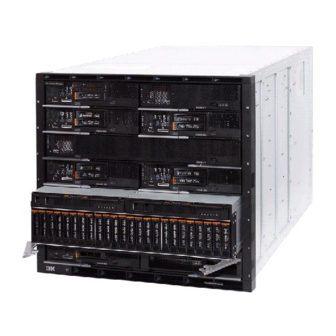
We now review the various components of the IBM Flex System in order to understand how IBM Flex System V7000 Storage Node integrates with the PureFlex Systems solution. All of the components are used in the three pre-integrated offerings to support compute, storage, and networking requirements. - Page 31 Figure 1-4 shows the chassis with IBM Flex System V7000 Storage Node occupying 4 x compute bays, which is partially inserted into the chassis for identification. Figure 1-4 Front view of IBM Enterprise Flex System Chassis with an IBM Flex System V7000 Storage Node The chassis has the following features on the front:...
- Page 32 Chassis Name Bay ID Individual components will then be able to work out their bay in the chassis, the IBM Flex System V7000 Storage Node enclosure uses 4 bays (double wide and double tall) per enclosure and will report its bay as the lowest left bay that it occupies.
-
Page 33: Chassis Power Supplies
40 mm cooling fan modules that pick power up from the midplane, not from the power supply. Availability: The 2100W power supplies are only available by Configure to Order (CTO). For more information about the 2100W power supply, see IBM PureFlex System and IBM Flex System Products and Technology, SG24-7984. Highlights The chassis allows configurations of power supplies to give N+N or N+1 redundancy. -
Page 34: Fan Modules And Cooling
(PSU) redundancy. In general, ‘N’ is the minimum number of PSUs required to keep the server operational, in this case, to keep the populated IBM Flex System Enterprise Chassis operational. The term ‘N+1’ is the minimum number of PSUs plus one. It is not the best option for redundancy, it is the equivalent of a “hot spare”... -
Page 35: Compute Nodes
The 12.9 kW figure is only a potential maximum, where the most power hungry configuration is chosen and all power envelopes are maximum. For a more realistic figure, the IBM Power Configurator tool can be made to establish specific power requirements for a given configuration. -
Page 36: Ibm Flex System X240 Compute Node
See IBM Flex System x440 Compute Node, TIPS0886 for more information. 1.4.2 IBM Flex System x240 Compute Node The IBM Flex System x240 Compute Node, available as machine type 8737, is a half-wide, two-socket server running the latest Intel Xeon processor E5-2600 family processors. It is ideal for infrastructure, virtualization, and enterprise business applications and is compatible with the IBM Flex System Enterprise Chassis. - Page 37 The IBM Flex System x240 Compute Node type 8737 features the Intel Xeon E5-2600 series processors with two, four, six, or eight cores per processor, with up to 16 threads per socket. The processors have up to 20 MB of shared L3 cache, Hyper-Threading, Turbo Boost Technology 2.0 (depending on processor model), two QuickPath Interconnect (QPI) links that...
- Page 38 There is also another expansion connector designed for future expansion options. The I/O expansion connectors are a very high-density 216 pin PCIe connector. By installing I/O adapter cards, it allows the x240 to connect with switch modules in the IBM Flex System Enterprise Chassis.
-
Page 39: Ibm Flex System X220 Compute Node
1.4.3 IBM Flex System x220 Compute Node The IBM Flex System x220 Compute Node, machine type 7906, is the next generation cost-optimized compute node designed for less demanding workloads and low-density virtualization. The x220 is efficient and equipped with flexible configuration options and advanced management to run a broad range of workloads. -
Page 40: Ibm Flex System P260 And P24L Compute Nodes
System Enterprise Chassis units to provide a high-density, high-performance compute node environment, using advanced processing technology. The IBM Flex System p24L Compute Node shares several similarities to the IBM Flex System p260 Compute Node in that it is a half-wide, Power Systems compute node with two POWER7 processor sockets,16 memory slots, two I/O adapter slots, and an option for up to two internal drives for local storage. - Page 41 Figure 1-11 IBM Flex System p260 Compute Node with front panel details There is no onboard video capability in the Power Systems compute nodes. The machines have been designed to be accessed using Serial Over LAN (SOL) or the IBM Flex System Manager (FSM).
-
Page 42: Ibm Flex System P460 Compute Node
A Flexible Service Processor (FSP) provides out-of-band system management capabilities, such as system control, run-time error detection, configuration, and diagnostics. Generally, you do not interact with the FSP directly but, rather, using tools, such as IBM Flex System Manager, IBM Flex System Chassis Management Module, and external IBM Systems Director Management Console. - Page 43 4 GB (2 x 2 GB) but that is not sufficient for reasonable production use of the machine. It is recommended for the IBM Flex System p460 Compute Node a minimum of 32 GB of memory, with 32 x 16 GB DIMMs the maximum memory configurable is 512 GB.
-
Page 44: I/O Modules
There are four I/O adapter slots on the IBM Flex System p460 Compute Node. The I/O adapters for the p460 have their own connector that plugs into the IBM Flex System Enterprise Chassis midplane. -
Page 45: Ibm Flex System Fabric Cn4093 10 Gb Converged Scalable Switch
It is shown on the node in Bay 2 in Figure 1-14. 1.5.1 IBM Flex System Fabric CN4093 10 Gb Converged Scalable Switch The IBM Flex System Fabric CN4093 10 Gb Converged Scalable Switch provides support for L2 and L3 switching, Converged Enhanced Ethernet (PFC, ETS, DCBX), Fibre Channel over Ethernet (FCoE), NPV Gateway, and Full Fabric Fibre Channel Forwarder (FCF). -
Page 46: Ibm Flex System Fabric En4093 And En4093R 10 Gb Scalable Switch
A Web browser-based interface (https/http) connection to the switch 1.5.2 IBM Flex System Fabric EN4093 and EN4093R 10 Gb Scalable Switch The IBM Flex System Fabric EN4093 and EN4093R 10 Gb Scalable Switches are 10 Gb 64-port upgradable midrange to high-end switch module, offering Layer 2/3 switching designed to install within the I/O module bays of the Enterprise Chassis. -
Page 47: Ibm Flex System En4091 10 Gb Ethernet Pass-Thru
If four-port adapters are installed in the compute nodes, ports 3 and 4 on those adapters are not enabled. For more information about the IBM Flex System EN4091 10 Gb Ethernet Pass-thru, see IBM Flex System EN4091 10Gb Ethernet Pass-thru Module, TIPS0865. -
Page 48: Ibm Flex System Fc5022 16 Gb San Scalable Switch
1.5.5 IBM Flex System FC5022 16 Gb SAN Scalable Switch The IBM Flex System FC5022 16 Gb SAN Scalable Switch is a high-density, 48-port 16 Gbps Fibre Channel switch that is used in the Enterprise Chassis. The switch provides 28 internal ports to compute nodes by way of the midplane, and 20 external SFP+ ports. -
Page 49: Ibm Flex System Fc3171 8 Gb San Pass-Thru
1.5.7 IBM Flex System FC3171 8 Gb SAN Pass-thru The IBM Flex System FC3171 8 Gb SAN Pass-thru I/O module is an 8 Gbps Fibre Channel pass-thru SAN module that has 14 internal ports and six external ports. It is shipped with all ports enabled. -
Page 50: Introduction To Ibm Flex System Storage
1.6 Introduction to IBM Flex System storage Either the IBM Storwize V7000 or IBM Flex System V7000 Storage Node is an integrated part of the IBM PureFlex System, depending on the model. Figure 1-15 shows an IBM Flex System V7000 Storage Node, where the left controller, called a cannister, is taken out. For the IBM Storwize V7000 products, the cannisters mount from the rear, whereas in IBM Flex System V7000 Storage Node, the controllers mount from the front. - Page 51 IBM Flex System V7000 Storage Node is designed to integrate into the IBM PureFlex System or IBM Flex System to enable extremely rapid storage deployment and breakthrough management simplicity. This new class of storage system combines no-compromise design along with virtualization, efficiency, and performance capabilities of IBM Storwize V7000. It...
- Page 52 30 percent compared to a configuration using only HDD. Extraordinary storage efficiency IBM Storwize V7000 and IBM Flex System V7000 Storage Node combine a variety of IBM technologies including thin provisioning, automated tiering, storage virtualization, Real-time Compression, clustering, replication, multi-protocol support, and a next-generation graphical user interface (GUI).
- Page 53 With their virtualized storage design and tight affinity with technologies such as IBM PowerVM and VMware, IBM Storwize V7000, IBM Flex System V7000 Storage Node, and IBM Storwize V7000 Unified are the ideal complement for virtualized servers that are at the heart of cloud deployments.
-
Page 54: Benefits And Value Proposition
For more information about External storage virtualization, see Chapter 7, “Storage Migration Wizard” on page 283. 1.6.2 Benefits and value proposition With IBM Storwize V7000 and IBM Flex System V7000 Storage Node, you get the following benefits: Simplified management and intuitive Graphical User Interface (GUI) aid in rapid implementation and deployment. -
Page 55: External Storage
FlashCopy and snapshot functions create instant copies of data to minimize data loss. 1.7 External storage In addition to IBM Flex System V7000 Storage Node, the IBM Flex System Enterprise Chassis offers several possibilities for integration into storage infrastructure, such as Fibre Channel, iSCSI, and Converged Enhanced Ethernet. -
Page 56: Ibm Storwize V7000
Center (SSIC): http://www.ibm.com/systems/support/storage/ssic/interoperability.wss For the purpose of this book, we limit the information to IBM Storwize V7000. For more information about the other supported IBM System Storage products, see IBM PureFlex System and IBM Flex System Products and Technology, SG24-7984. -
Page 57: Chapter 2. Introduction To Ibm Flex System V7000 Storage Node
We present the concepts of virtualized storage and show how it works with IBM Flex System V7000 Storage Node, as well as briefly describing the many software features and capabilities that are available with this environment. -
Page 58: Ibm Flex System V7000 Storage Node Overview
When virtualizing external storage arrays, IBM Flex System V7000 Storage Node can provide up to 32 PB of usable capacity. IBM Flex System V7000 Storage Node supports a range of external disk systems similar to what the IBM Storwize V7000 system supports today. A control enclosure contains two control canisters;... -
Page 59: Ibm Flex System V7000 Storage Node Terminology
IBM Flex System V7000 Storage Node introduces some new terminology, which is defined in Table 2-1. We also include the terms first introduced with the IBM SVC and the IBM Storwize V7000, which are important in order to understand the rest of the implementation procedures described in this publication. - Page 60 Volume As used with IBM Flex System V7000 Storage Node environments, it is the virtually defined device created for use by the host or IBM Flex System V7000 Storage Node cluster to store I/O data. IBM Flex System V7000 Storage Node Introduction and Implementation Guide...
-
Page 61: Ibm Flex System V7000 Storage Node
2.3 IBM Flex System V7000 Storage Node IBM Flex System V7000 Storage Node is based on two enclosure types; the IBM Flex System V7000 Control Enclosure and the IBM Flex System V7000 Expansion Enclosure. Both of these enclosures reside in a newly designed common chassis that fits into the IBM Flex System Enterprise chassis. -
Page 62: Ibm Flex System V7000 Storage Node Releases
Table 2-3 shows that the maximum number of hosts, LUNs, and WWPNs have been increased for version 7.1.x or later to enhance the scalability of IBM Flex System V7000 Storage Node and meet high demand customer environments. IBM Flex System V7000 Storage Node Introduction and Implementation Guide... -
Page 63: Ibm Flex System V7000 Storage Node Functions
Note: Current limits are 512/2048 per iogrp/cluster (generally available) and 2048/8192 per cluster (RPQ required). This increase would apply equally to native FC and FCoE WWPNs For a complete and updated list of IBM Flex System V7000 Storage Node configuration limits and restrictions, see the following website: http://www.ibm.com/support/docview.wss?uid=ssg1S1004369 2.3.3 IBM Flex System V7000 Storage Node functions... - Page 64 – Multitarget FlashCopy: IBM Flex System V7000 Storage Node supports copying of up to 256 target volumes from a single source volume. Each copy is managed by a unique mapping and, in general, each mapping acts independently and is not affected by other mappings sharing the source volume.
- Page 65 – Move volumes non-disruptively onto a newly installed storage system – Move volumes to rebalance a changed workload – Migrate data from other back-end storage to IBM Flex System V7000 Storage Node managed storage IBM System Storage Easy Tier (license included on the base license for IBM Flex System...
-
Page 66: Ibm Flex System V7000 Storage Node Licensing
With this feature, an external storage subsystem can be attached through the Fibre Channel or by FCoE to IBM Flex System V7000 Storage Node. These devices cannot be presented through an iSCSI connection. The devices presented are treated as mdisks and can be mapped to storage pools for volume creation and management. -
Page 67: Optional Licensing
IBM Flex System V7000 Storage Node optional licenses are described next. External Virtualization Each IBM Flex System V7000 Storage Node Disk Control Enclosure has the ability to attach and manage external storage devices on the SAN in the same way as the SAN Volume Controller. - Page 68 For example, adding a DS5020 consisting of three enclosures to an IBM Flex System V7000 Storage Node consisting of one control enclosure and one expansion enclosure, then you will need one license with quantity of three enclosure authorization feature codes (one for each of the DS5020 enclosures) of the IBM Flex System V7000 External Virtualization software.
- Page 69 Base Software and each external enclosure licensed with the IBM Flex System V7000 External Virtualization Software. For example, if you have IBM Flex System V7000 consisting of one control enclosure and one expansion enclosures, managing a DS5020 consisting of four enclosures (four External...
- Page 70 IBM Flex System V7000 Storage Node. In order to facilitate this migration, IBM allows customers 45 days from the date of purchase of IBM Flex System V7000 Storage Node to use the external virtualization function for the purpose of migrating data from an existing storage system to IBM Flex System V7000 Storage Node.
-
Page 71: Ibm Flex System V7000 Storage Node Hardware
2.5 IBM Flex System V7000 Storage Node hardware The IBM Flex System V7000 Storage Node solution is a modular storage system that is built to interface and reside within the IBM Flex System Enterprise Chassis. When sold in the IBM PureFlex system, it will come with a four port FC host interface card (HIC) preinstalled in it and configured to the FC switches in the Flex Enterprise Chassis. - Page 72 2-port 10 Gbps Ethernet CNA network adapter or a 4 port 8 Gbps Fibre Channel network adapter. Figure 2-4 is a logical block diagram of the components and flow of the control canister. Figure 2-4 Logical block diagram for control canister IBM Flex System V7000 Storage Node Introduction and Implementation Guide...
- Page 73 There are also two USB connections available for support use to perform maintenance actions as required. Figure 2-5 Control enclosure with connection ports and indicators Chapter 2. Introduction to IBM Flex System V7000 Storage Node...
- Page 74 Fast blink - Charging, and does not have enough. power to boot the canister (Error 656). On solid - Fully charged. Fault On - Hardware fault detected. IBM Flex System V7000 Storage Node Introduction and Implementation Guide...
-
Page 75: Expansion Canister
As the indicators on the expansion enclosure are a subset of the ones that are available on the control enclosure, Table 2-5 on page 54 provides the details of their definitions. Chapter 2. Introduction to IBM Flex System V7000 Storage Node... -
Page 76: Supported Disk Drives
Figure 2-8 Logical block diagram for control canister 2.5.3 Supported disk drives Both the IBM Flex System V7000 Control Enclosure and the IBM Flex System V7000 Expansion Enclosure support up to 24 2.5 inch disk drives in their enclosures. Table 2-6 shows all the possible drive types that can be used in the internal enclosure drive slots at the time of writing. -
Page 77: Ibm Storwize V7000 Expansion Enclosure
Storwize V7000 expansion enclosure, as well as to connect any additional IBM Storwize V7000 expansion enclosure behind it. The ports are numbered 1 on the left and 2 on the right. SAS port 1 is the IN port and SAS port 2 is the OUT port. There is also a symbol printed at the ports to identify whether it is an IN or an OUT bound port. -
Page 78: Sas Cabling Requirements
1 - 24, starting from the left. (There is a vertical center drive bay molding between slots 12 and 13.) Though the IBM Storwize V7000 2076-224 enclosure is a 2.5 inch, 24 drive slot chassis; the drives of this subsystem are not interchangeable with IBM Flex System V7000 Storage Node drives. -
Page 79: Ibm Flex System V7000 Storage Node Components
Figure 2-12 Node cabling internal SAS and external Notice that IBM Flex System V7000 Storage Node cabling is done directly from top to bottom down through its expansions, including any additional external expansions. -
Page 80: Hosts
2.6.1 Hosts A host system is an IBM Flex System compute node that is connected to IBM Flex System V7000 Storage Node through a Fibre Channel connection or through an Ethernet connection using either iSCSI or Fibre Channel over Ethernet (FCoE) connection through the switch modules of the IBM Flex System. -
Page 81: I/O Groups
(or at the least outside of the SAN). When you are unable to access IBM Flex System V7000 Storage Node, you do not have access to the backup data if it is on the SAN. -
Page 82: Raid
(CLI), 2.6.5 RAID The IBM Flex System V7000 Storage Node setup contains a number of internal disk drive objects known as candidate drives, but these drives cannot be directly added to storage pools. The drives need to be included in a Redundant Array of Independent Disks (RAID) grouping used for performance and to provide protection against the failure of individual drives. -
Page 83: Managed Disks
Node virtualizes. This unit could be a logical volume from an external storage array presented to IBM Flex System V7000 Storage Node or a RAID array created on internal drives, or an external Storwize V7000 expansion that is managed by IBM Flex System V7000 Storage Node. -
Page 84: Storage Pools
The name can be a maximum of 63 characters. Valid characters are uppercase (A-Z), lowercase letters (a-z), digits (0 - 9), underscore (_), period (.), hyphen (-), and space; however, the names must not begin or end with a space. IBM Flex System V7000 Storage Node Introduction and Implementation Guide... - Page 85 256 TB 128 MB 512 TB 256 MB 1 PB 512 MB 2 PB 1024 MB 4 PB 2048 MB 8 PB 4096 MB 16 PB 8192 MB 32 PB Chapter 2. Introduction to IBM Flex System V7000 Storage Node...
- Page 86 Chapter 10, “Volume mirroring and migration” on page 447. For most IBM Flex System V7000 Storage Nodes, a maximum of capacity of 1 PB is sufficient; and an extent size value of 256 MB should be used.
-
Page 87: Volumes
A multi-tiered storage pool is used to enable automatic migration of extents between disk tiers using the IBM Flex System V7000 Storage Node Easy Tier function. Figure 2-14 shows these components. Figure 2-14 IBM Flex System V7000 Storage Node with single tier and multi tier pools 2.6.9 Volumes... - Page 88 Image mode: Image mode volumes are special volumes that have a direct relationship with one MDisk. They are used to migrate existing data into and out of IBM Flex System V7000 Storage Node. When the image mode volume is created, a direct mapping is made between extents that are on the MDisk and the extents that are on the volume.
-
Page 89: Thin-Provisioned Volumes
The real capacity determines the quantity of MDisk extents that are allocated for the volume. The virtual capacity is the capacity of the volume reported to IBM Flex System V7000 Storage Node and to the host servers. -
Page 90: Mirrored Volumes
When a host system issues a write to a mirrored volume, IBM Flex System V7000 Storage Node writes the data to both copies. When a host system issues a read to a mirrored volume, IBM Flex System V7000 Storage Node requests it from the primary copy. -
Page 91: Easy Tier
The usage statistics file can be offloaded from IBM Flex System V7000 Storage Node and then an IBM Storage Advisor Tool can be used to create a summary report from the data. Contact your IBM representative or IBM Business Partner for more information about the Storage Advisor Tool. -
Page 92: Real-Time Compression
2.6.13 Real-time Compression With IBM Flex System V7000 Storage Node, there is a capability to create a volume as a compressed volume type. With this type of volume, storage capacity needs can be lowered by more than half. - Page 93 Optionally, a colon (:), followed by a string of the assigning organization’s choosing, which must make each assigned iSCSI name unique. For IBM Flex System V7000 Storage Node the IQN for its iSCSI target is specified as: iqn.1986-03.com.ibm:2145.<clustername>.<nodename> On a Windows server, the IQN, that is, the name for the iSCSI initiator, can be defined as: iqn.1991-05.com.microsoft:<computer name>...
-
Page 94: Fibre Channel Over Ethernet (Fcoe)
SCSI. Be aware that because the system and node name are part of the IQN for IBM Flex System V7000 Storage Node, you can lose access to your data by changing these names. The IBM Flex System V7000 Storage Node GUI shows a specific... -
Page 95: Advanced Copy Services
IBM Flex System V7000 Storage Node also permits multiple target volumes to be FlashCopied from the same source volume. This capability can be used to create images from separate points in time for the source volume, and to create multiple images from a source volume at a common point in time. -
Page 96: Ibm Flex System V7000 Remote Mirroring Software
Remote deployments for disaster recovery for current SVC and Storwize V7000 environments can easily be fitted with IBM Flex System V7000 Storage Node or vice versa. The Copy Services layer sits above and operates independently of the function or characteristics of the underlying disk subsystems used to provide the storage resources to IBM Flex System V7000 Storage Node. -
Page 97: Synchronous / Asynchronous Remote Copy
Customers who want to use the global mirror capability with Flex System V7000 on a low bandwidth link between sites can do so with the use of the low bandwidth remote mirroring. This capability provides options to help administrators balance network bandwidth... -
Page 98: Copy Services Configuration Limits
I/O groups. 2.8 Management and support tools The IBM Flex System V7000 Storage Node system can be managed through the IBM Flex System Management Node (FSM), or by using the native management software that runs in the hardware itself. -
Page 99: Ibm Assist On-Site And Remote Service
To use the IBM Assist On-site tool, the SSPC or master console must be able to access the Internet. The following website provides further information about this tool: http://www.ibm.com/support/assistonsite/... -
Page 100: Syslog Messages
The syslog protocol is a standard protocol for forwarding log messages from a sender to a receiver on an IP network. The IP network can be either IPv4 or IPv6. IBM Flex System V7000 Storage Node can send syslog messages that notify personnel about an event. IBM Flex System V7000 Storage Node can transmit syslog messages in either expanded or concise format. -
Page 101: Useful References From Storwize V7000 Websites
2.9 Useful references from Storwize V7000 websites Due to the common design of the software and procedures of the IBM Storwize V7000 and IBM Flex System V7000 Storage Node, the following information is provided for additional references: IBM Flex System Information Center: http://publib.boulder.ibm.com/infocenter/flexsys/information/index.jsp... -
Page 102: Ibm Virtual Storage Learning Videos On Youtube
Storage. With the common software design shared with this system and IBM Flex System V7000 Storage Node many of these can be used to help develop a familiarity with the terminology and many of the GUI and management processes. They are available at the websites shown in Table 2-11. -
Page 103: Chapter 3. Systems Management
System Manager Node, and shows how to use the navigation tools. While there are several ways to manage the various components of the IBM Flex Systems, a description of all these options is beyond the scope of this publication. In this chapter, we cover the management options related to IBM Flex System V7000 Storage Node and the I/O modules. -
Page 104: System Management Overview
3.1 System Management overview The IBM PureFlex System is designed to improve efficiency in system management. A variety of functions and features are designed towards providing a simplified yet dynamic management experience to the user: Advanced automation of configuration and management... - Page 105 IBM Flex System Chassis Management Module (CMM) CMM is the default integrated platform for managing a single IBM Flex System Enterprise Chassis. It occupies one of the two chassis management bays on the rear of the chassis. A second module can be installed for redundancy.
-
Page 106: Ibm Flex System Storage Management
System Manager. IBM Flex System V7000 Storage Node IBM Flex System V7000 Storage Node is physically and logically integrated into an IBM Flex System. IBM Flex System V7000 Storage Node is designed on the industry-leading storage virtualization and efficiency capabilities of IBM Storwize V7000 by simplifying and speeding... -
Page 107: Storage Management Interfaces
Starting Level: IBM Flex System Manager Chassis Map The IBM Flex System Manager offers a Chassis Map, which is the single point of management and starting point for IBM Flex System. It allows for physical navigation through the entire system, as shown in Figure 3-1. - Page 108 Upper Level: IBM Flex System Manager Storage Control Higher level data center management can be achieved using the IBM Flex System Manager Storage Control feature. It provides integrated management with a Systems and Storage perspective. Using Storage Control, you can manage storage across your data center connected to the IBM Flex System, and also map connections between servers, switches and storage.
- Page 109 Detailed Level: IBM Flex System V7000 Storage Node User Interface This interface is inherent in every IBM Flex System V7000 Storage Node. It allows for detailed disk setup (RAID arrays and LUNs). All the advanced disk features such as Easy Tier, Mirroring, Clustering, and Virtualization can be configured using the IBM Flex System V7000 Storage Node User Interface.
-
Page 110: Ibm Flex System Chassis Management Module (Cmm)
System at the chassis level, simplifying installation and management of your installation. The CMM is central to the management of the chassis, and is required in the IBM Flex System Enterprise Chassis. One CMM comes standard with the chassis. There are two CMM bays in the chassis, giving the user an option to add a second CMM for redundancy. - Page 111 The IBM Flex System Chassis Management Module web-based graphical user interface (GUI) provides a way to perform CMM functions within a supported web browser. This user interface is a program that is part of the firmware on IBM Flex System Chassis Management Module.
-
Page 112: Accessing The Cmm
3.2.2 Accessing the CMM After initial connection, you need to configure the IBM Flex System Enterprise Chassis and its components for your operating environment. When the chassis is started, all installed components will be discovered and the vital product data (VPD) of each component is stored in the IBM Flex System Chassis Management Module. - Page 113 An Initial Setup wizard starts automatically the first time you access the web interface of a new CMM or a CMM that has been reset to its default settings. For more information regarding initial setup of the CMM, see Implementing Systems Management of IBM PureFlex System, SG24-8060.
-
Page 114: Viewing And Configuring Ip Addresses Of Chassis Components
IP addresses of devices in a solution is of a great advantage to IT Administrators and Users. The IBM Flex System IBM Flex System Chassis Management Module gives options to conveniently find the IP information of all chassis components in a single view, and gives the ability to easily configure the networking options for a device. - Page 115 A window opens, giving a single location to view the IP addresses of various chassis Components. If you want to view the IP address of a certain component instantly, you can just scroll the mouse pointer over the View option. This action opens a pop-up window that shows the IPv4 and IPv6 addresses of that device, as shown in Figure 3-8.
-
Page 116: Accessing I/O Modules Using Cmm
, as shown in Figure 3-9. Figure 3-9 IP Address Configuration You can also view and configure IP addresses using IBM Flex System Manager as well as the node-specific management controllers. There are numerous functions and features offered by the IBM Flex System Chassis Management Module that are beyond the scope of this publication. - Page 117 Figure 3-10 CMM - Accessing I/O modules The next view shows the available I/O modules in IBM Flex System. It also gives options to Power and Restart the modules as well as the Actions that can be performed on them, as shown in Figure 3-11.
- Page 118 The Properties window has multiple tabs, showing detailed information regarding the module. Click the IO Connectivity tab to view the connectivity details between the I/O module and the compute nodes in the IBM Flex System, as shown in Figure 3-13. Figure 3-13 IO Connectivity status of an I/O module To open the Module-specific Management interface, click the I/O Module wanted, then the Actions drop-down button, as shown in Figure 3-14.
-
Page 119: Managing Storage Using Ibm Flex System Chassis Management Module
Tip: Except for the top menu items, the remaining content of the page and other web interface pages will vary according to the type of IBM Flex System Enterprise Chassis that you are using and the firmware versions and options that are installed. - Page 120 Figure 3-17 CMM - Details of the selected Chassis component System Information (blue) button, which is located above the graphical representation of the Chassis, gives a quick view of the selected component’s information. IBM Flex System V7000 Storage Node Introduction and Implementation Guide...
- Page 121 The quick view includes part information, serial number, health and temperature, and unique identity (depending on the component), as shown in Figure 3-18. Figure 3-18 CMM - System Information Quick View Chapter 3. Systems management...
- Page 122 Figure 3-19 CMM - Actions for Chassis Component In Figure 3-19, an IBM Flex System V7000 Storage Node canister is seen as selected (blue rectangle around component). On the right-side of the Chassis rear view, there is a list of...
- Page 123 IT administrators have to ensure that all equipment stays below the temperature, power, and voltage thresholds at all times. The IBM Flex System Chassis Management Module web interface provides multiple views to facilitate monitoring and notification of environmental and temporal indices.
- Page 124 Figure 3-24 shows the DC Power consumption for the component. Figure 3-24 Power consumption of selected chassis component The IBM Flex System Chassis Management Module web interface has a menu structure at the top of each page that gives easy access to most management functions. One of the most frequently used menu items, Chassis Management, shows properties, settings, and various views and reports regarding the nodes, modules, and other components in the chassis.
- Page 125 Figure 3-25 shows the option that gives the hierarchical view of chassis components. Figure 3-25 Hardware Topology view from Chassis Management menu The Chassis Hardware Topology view provides very detailed information regarding all the hardware in the chassis. It goes deep to the point where you can select individual drives, batteries, and even expansion cards within a storage or compute node, as shown in Figure 3-26.
- Page 126 In the Storage Node view, you can select the column headers depending on how much detail is wanted, as shown in Figure 3-29. Figure 3-29 CMM - Storage Nodes view - columns IBM Flex System V7000 Storage Node Introduction and Implementation Guide...
- Page 127 The IBM Flex System V7000 Storage Node User Interface is used for detailed-level management and configuration of IBM Flex System V7000 Storage Node. Click Actions Launch Storage Node Controller Console, which will take you to the IBM Flex System V7000 Storage User Interface, as shown in Figure 3-31.
- Page 128 Figure 3-32. Figure 3-32 IBM Flex System V7000 Storage Node Login window After logging in, you can use the IBM Flex System V7000 Storage User Interface directly to perform the management tasks, as shown in Figure 3-33.
-
Page 129: Data Collection Using Cmm
3.2.6 Data collection using CMM The IBM Flex System Chassis Management Module offers various powerful options to pull Service and Support service information from the components in chassis. The menu allows the user to view a list of serviceable problems and their current status, enable and configure electronic Call Home capability, review detailed status about CMM’s health and connectivity,... - Page 130 Figure 3-36 Initiate and Collect The system will prompt you for verification, indicate that operation is in progress, and then its completion, as shown in Figure 3-37. Figure 3-37 Status dialog boxes IBM Flex System V7000 Storage Node Introduction and Implementation Guide...
- Page 131 To view or delete files in the CMM local storage file system, select Mgt. Module Management File Management, as shown in Figure 3-38. Figure 3-38 File Management The File Management page shows the status of CMM’s local storage file system and the CMM File Management menu, as shown in Figure 3-39.
- Page 132 The file containing a dump of service data is also copied in /tftproot/service/ for ease of transfer, as shown in Figure 3-41. Figure 3-41 Viewing service data in /tftp/service/ path For more details regarding the IBM Flex System Chassis Management Module, visit the following website: http://publib.boulder.ibm.com/infocenter/flexsys/information/topic/com.ibm.acc.cmm .doc/cmm_product_page.html...
-
Page 133: Flex System Manager
It simplifies management by facilitating faster implementation, reconfiguration and provisioning of server, storage and network resources. It acts as a single-point of support across all assets and resources in IBM PureFlex Systems for the complete range of management tasks, including service requests, incident handling and problem resolution, as well as handling specialized management tasks in connection with security, performance, resource allocation, and application version control, and so on. - Page 134 The IBM Flex System supports a secure policy by default to ensure a secure chassis infrastructure, and a Legacy policy that offers flexibility in chassis security. All components run the same security policy. A centralized security policy makes Enterprise Chassis easy to configure.
-
Page 135: Ibm Flex System Manager Storage Management Features
IBM Flex System V7000 Storage Node: Integrated virtualized IBM Flex System Storage IBM Flex System Storage Virtualization: Used to virtualize external storage for greater data center efficiency and utilization (such as IBM Storwize V7000, IBM Flex System V7000 Storage Node, and IBM SAN Volume Controller) IBM Flex System Storage Interoperability: A broad set of IBM storage is supported with IBM Flex System. - Page 136 The interoperability is illustrated in Figure 3-43. Figure 3-43 Storage Interoperability IBM Flex System Manager is the common management interface used in an IBM Flex System for multi-chassis management. It offers features for simplified administration of storage along with server and network management. The integrated storage management with Flex System Manager offers simplified storage virtualization capabilities.
- Page 137 IBM Flex System Manager base feature set The following functionality and features are available at this time in the IBM Flex System Manager base feature set: Support for up to four managed chassis, and up to 5,000 managed elements...
- Page 138 Pool management (VMControl Enterprise) IBM Fabric Manager (IFM) IBM Fabric Manager (IFM) is available as a Feature on Demand (FoD) through the IBM Flex System Manager management software. It is an easy-to-use server provisioning I/O management tool. Unlike performing deployment steps manually, the parameters are configured automatically.
-
Page 139: Logging In To The Ibm Flex System Manager Node
There are minimum hardware and software requirements that the system must meet before you can install or use IFM, which are documented in detail at the following website: http://publib.boulder.ibm.com/infocenter/flexsys/information/topic/com.ibm.acc.iof m.doc/dw1li_creating_a_configuration_file_automatically.html For information regarding how to install, configure, and use IBM Fabric Manager (IFM), visit this website: http://publib.boulder.ibm.com/infocenter/flexsys/information/topic/com.ibm.acc.iof m.doc/dw1li_advanced.html 3.3.3 Logging in to the IBM Flex System Manager Node... -
Page 140: Overview Of Ibm Flex System Manager And Ibm Fsm Explorer
3. After a successful login, you are taken to the default Home page of IBM Flex System Manager. Figure 3-46 shows the FSM Home page. Figure 3-46 FSM - Startup Page 3.3.4 Overview of IBM Flex System Manager and IBM FSM Explorer The new GUI on IBM Flex System Manager provides two interfaces, which we discuss in the following sections. - Page 141 Figure 3-47 FSM chassis manager tab This figure shows the FSM chassis manager window, whick offers the following functions: Clicking the chassis name opens IBM FSM Explorer, covered later in this section. The global search tab helps in finding tasks and hardware resources.
- Page 142 IBM FSM Explorer This section gives you a short overview on how to navigate around in the IBM FSM Explorer. IBM FSM Explorer has a horizontal pull-down menu, and a vertical menu. The horizontal menu is divided into two menus, one in the top black frame, showing health and job status, and the second in the blue frame, which guides you to different tasks and hardware recourses.
- Page 143 To get to IBM FSM Explorer, click Launch IBM FSM Explorer in the home tab of IBM Flex System Manager. It will open IBM FSM Explorer in a new tab. Figure 3-49 shows the IBM FSM Explorer home page. Figure 3-49 IBM FSM Explorer home - tabs When working in IBM FSM Explorer, it is important to know that some tasks will be opened in IBM FSM Explorer, and other tasks will be opened in IBM Flex System Manager.
- Page 144 Power systems management shows all power systems recourses. Configuration takes you to the configuration patterns. Firmware takes you to Update Manager in the IBM Flex System Manager. Figure 3-52 shows the Systems menu. Figure 3-52 IBM FSM Explorer - Systems menu...
- Page 145 Jobs gives you a shortcut to the Active and Scheduled Jobs page. Figure 3-53 shows the Monitor menu. Figure 3-53 IBM FSM Explorer - Monitor menu The Security menu is divided into two groups: Permissions gives you shortcuts to Users and Groups, Roles, and Credentials, which are used to give access and rights.
- Page 146 Service and Support page, which allows you to configure the system to automatically report errors to IBM; and Server Auditing, which takes you to the Credentials page. Administration gives you links to Administration, Plug-ins, and Applications tab in the IBM Flex System Manager Home page.
- Page 147 Figure 3-56 IBM FSM Explorer - Vertical menu The Chassis page gives you an overview of what is installed in one or more chassis, as shown in Figure 3-57. Figure 3-57 IBM FSM Explorer Chapter 3. Systems management...
- Page 148 To get to the chassis map, click the chassis in the vertical menu in Figure 3-56 on page 127, then click the chassis under the chassis list as shown here in Figure 3-58. Figure 3-58 IBM FSM Explorer home tab - chassis map IBM Flex System V7000 Storage Node Introduction and Implementation Guide...
- Page 149 The chassis view shows a map of the front and back with a graphical representation of the components, as shown in Figure 3-59. Figure 3-59 IBM FSM Explorer chassis map To get detailed information about the chassis and chassis components, click View Details in the summary field of Figure 3-59.
- Page 150 Hardware map at the left side. The detailed information regarding the chassis is shown below the Hardware map at the right side. Figure 3-60 IBM FSM Explorer chassis details IBM Flex System V7000 Storage Node Introduction and Implementation Guide...
- Page 151 A drop-down menu shows the actions that can be performed at the Chassis level, as shown in Figure 3-61. Figure 3-61 IBM FSM Explorer - Component Actions The Host page gives you an overview of Hosts as shown in Figure 3-62.
- Page 152 Figure 3-64. Figure 3-64 IBM FSM Explorer - Storage page Right-clicking an IBM Flex System V7000 Storage Node gives you the possibility to update firmware as shown in Figure 3-65. Figure 3-65 IBM FSM Explorer - Storage page - Firmware update...
- Page 153 From the menu shown in Figure 3-65 on page 132, you can also launch the IBM Storwize V7000 Element manager, as seen in Figure 3-66. Figure 3-66 IBM FSM Explorer - Storage page - launch IBM Storwize V7000 Element manager Choosing the option to Launch the IBM Storwize V7000 Element Manager will open the IBM Flex System V7000 Storage Management login page, as shown in Figure 3-67.
- Page 154 Figure 3-68. Figure 3-68 IBM FSM Explorer - Storage page - Switch overview Double-clicking one of the switches leads you to detailed information about the switch, as shown in Figure 3-69.
-
Page 155: Accessing I/O Modules Using Fsm
Figure 3-71 shows the FC switch login page. Figure 3-71 FC Switch login 3.3.5 Accessing I/O modules using FSM In an IBM Flex system, node to node communication happens within the Chassis. Network Control Network Control is a plug-in that enables utilization of integrated network management capabilities of an FSM. - Page 156 Figure 3-72 IBM FSM Explorer - Network control This action will open up the Network Control interface, which shows management and configuration options for the IBM Flex System I/O Modules, as shown in Figure 3-73. Figure 3-73 Network Control Plug-in...
- Page 157 Selecting Ethernet Switches in Network Control interface opens a view of all available Ethernet Switches along with information regarding state, access, IP, and type, as shown in Figure 3-74. Figure 3-74 Viewing Ethernet Switches in FSM name Select a switch by clicking its given to go to the detailed management and configuration options for it, as shown in Figure 3-75.
- Page 158 Click the Inventory tab to view and gather Inventory for the selected switch module, as shown in Figure 3-76. Figure 3-76 Gathering Inventory information References For further details regarding the management and configuration of I/O Modules using IBM Flex System Manager, visit the following website: http://publib.boulder.ibm.com/infocenter/flexsys/information/topic/com.ibm.acc.873 1.doc/managing_network_resources.html...
-
Page 159: Data Collection Using Fsm
3.3.6 Data collection using FSM You can use IBM Flex System Manager to collect and submit support files for a managed resource. Support files can contain detailed system information used to help diagnose a serviceable hardware problem, dump files collected from a managed resource, event logs, and more. - Page 160 Figure 3-78. Figure 3-78 SSM default view To collect logs from IBM Flex System V7000 Storage Node using IBM Flex System Manager, click Manage support files as shown in Figure 3-78. The “Manage support files” page displays, and by choosing Collect support files, a new window appears, where you can see logs already collected.
- Page 161 Upload to ftp server: Upload to an ftp server on your network Copy to media: USB key, inserted into IBM Flex System Manager Node Download: Download the support file to the machines which are connected to the IBM Flex System Manager Figure 3-80 shows the options for a support file.
- Page 162 Collect as shown in Figure 3-82. Figure 3-82 IBM FSM - Collect support file - choose file type When the file has been collected, you can choose to download it, send it to IBM, or copy it to a media.
-
Page 163: Managing Storage Using Ibm Flex System Manager
Storage Control also extends the management capabilities and device coverage of the VMControl, which is a tool within the IBM Flex System Manager Node responsible for the life cycle management of virtual resources. This collaboration is leveraged in VMControl for tasks... - Page 164 To open Storage Management, choose Home Storage Control in the horizontal menu in IBM FSM Explorer as shown in Figure 3-83. Figure 3-83 IBM FSM Explorer - Storage Control IBM Flex System V7000 Storage Node Introduction and Implementation Guide...
- Page 165 The Storage Management window opens, showing all storage that is available in the managed IBM Flex Systems, as shown in Figure 3-84. Figure 3-84 FSM Storage Control Chapter 3. Systems management...
- Page 166 You can also manage storage by going to Home tab Additional Setup Manage System Storage, as shown in Figure 3-85. Figure 3-85 FSM - Manage System Storage IBM Flex System V7000 Storage Node Introduction and Implementation Guide...
- Page 167 To get more information about the storage systems controlled by IBM Flex System Manager and see which actions there can be performed, click Network Storage in the storage control window, as shown in Figure 3-86. Figure 3-86 FSM - Storage Control - Network storage This will open a new page showing Network attached storage, as shown in Figure 3-87.
- Page 168 Figure 3-88 FSM - Storage Control - Storage systems From this window, you are able to see General information, Eventlog, and Inventory of the storage system, by clicking the different tabs. IBM Flex System V7000 Storage Node Introduction and Implementation Guide...
- Page 169 Choosing the Actions pull-down button will allow you to collect inventory, update storage system firmware, and open the IBM Flex System V7000 Storage Node management application, as shown in Figure 3-89. Figure 3-89 FSM - Storage Control - Storage system action menu...
- Page 170 2. Resource Explorer shows a snapshot of all resources in the IBM Flex System Manager managed by the IBM Flex System Manager, as shown in Figure 3-91. Figure 3-91 Resource Explorer 3. Navigate to manage discovered storage, as shown in Figure 3-92.
- Page 171 4. Select target storage (for example, IBM Storwize V7000), as shown in Figure 3-93. Figure 3-93 Selecting target storage 5. Select the tab Inventory to collect the inventory, as shown in Figure 3-94. Figure 3-94 Inventory of Storage Chapter 3. Systems management...
- Page 172 Important: You must repeat this step each time you want to check for an event on these devices. 5. You will now receive TPC alerts for devices under the farm. IBM Flex System V7000 Storage Node Introduction and Implementation Guide...
- Page 173 Discovering new storage systems To discover new storage systems, from the storage management window, click Discover Storage as shown in Figure 3-96. Figure 3-96 FSM Storage Management - Discover Storage Chapter 3. Systems management...
- Page 174 Discover as shown in Figure 3-98. Figure 3-98 Discovering new storage - IP address and SSH private Key Important: When you use the management software to manage a Storwize V7000, the management software overwrites the preexisting SSH key for the user ID superuser. After the management process is complete, you can reapply the previous SSH key.
- Page 175 In this chapter, we have covered management of IBM Flex System V7000 Storage Node from CMM and FSM. For more information regarding CMM and FSM, see Implementing Systems Management of IBM PureFlex System, SG24-8060, and the IBM InfoCenter: http://publib.boulder.ibm.com/infocenter/flexsys/information/index.jsp?topic=%2Fco m.ibm.acc.pureflex.doc%2Fp7een_template_landing.html...
- Page 176 IBM Flex System V7000 Storage Node Introduction and Implementation Guide...
-
Page 177: Chapter 4. Ibm Flex System V7000 Storage Node Initial Configuration
Chapter 4. Node initial configuration This chapter provides the initial configuration steps of IBM Flex System V7000 Storage Node. Before the actual installation and the initial configuration, proper planning is important. We also present an overview of the planning tasks and refer you to the appropriate documentation as needed to enable you to complete these tasks. -
Page 178: Planning Overview
4.1 Planning overview We start with an overview of the planning tasks required for the proper installation of IBM Flex System V7000 Storage Node. 4.1.1 Hardware planning Proper planning before the actual physical installation of the hardware is required. Here is an... -
Page 179: San Configuration Planning
SAN fabric. For example, you can have a SAN that contains one host that runs on an IBM AIX operating system and another host that runs on a Microsoft Windows operating system. -
Page 180: Management Ip Address Considerations
NTP, SNMP, SMTP, and Syslog systems, if configured. The management IP address is configured during first-time setup of your IBM Flex System V7000 Storage Node. See 4.3, “IBM Flex System V7000 Storage Node Setup Wizard” on page 170. -
Page 181: Management Interface Planning
CMM for redundancy. The CMM provides system-management functions for all components in an IBM Flex System Enterprise Chassis. It controls a serial port for connection to a local console or a serial management network and supports data rates of 10/100 Mbps and 1 Gbps with auto negotiate. -
Page 182: Initial Setup For Ibm Flex System V7000 Storage Node
V7000 Storage Node system for the first time in this configuration. Choosing a method There are two methods that can be used for the initial setup of IBM Flex System V7000 Storage Node. The method used depends upon the configuration of the IBM Flex System:... -
Page 183: Using Fsm For Initial Setup
IBM Service and Support. 4.2.1 Using FSM for initial setup Now that you have installed IBM Flex System V7000 Storage Node in the chassis with supported level of code, you can create and configure a clustered system using the FSM. The... - Page 184 2. In the Chassis Manager, select the applicable chassis which will launch the Chassis Map for that chassis, as shown in Figure 4-3. Figure 4-3 IBM Flex System Manager - Hardware Map IBM Flex System V7000 Storage Node Introduction and Implementation Guide...
- Page 185 Wait while the status is processed. After the status is processed, the status changes to Success, and the message changes to Managed. g. Click Done. Figure 4-4 Add a chassis into Chassis Manager Chapter 4. IBM Flex System V7000 Storage Node initial configuration...
- Page 186 4. Navigate to General Actions and click Launch IBM Flex System V7000 Storage Node Manage (V7000) as shown in Figure 4-5 to start the Initial Setup wizard. If you do not see this option, examine the Service IP setting for the storage node. For details, see 4.5.1, “Changing the Service IP address”...
-
Page 187: Using Cmm For Initial Setup
For more details on the rest of the setup wizard steps, see 4.3, “IBM Flex System V7000 Storage Node Setup Wizard” on page 170. - Page 188 Follow this procedure for the initial setup from the CMM interface: 1. Log in to the CMM and navigate to the Chassis Map. In the Chassis Map displayed by the CMM, you will see all the IBM Flex System V7000 Storage Node enclosures installed in the chassis.
- Page 189 – If you have problems connecting to the service address, see the Cannot connect to the service assistant topic in the IBM Flex System V7000 Storage Node Troubleshooting, Recovery, and Maintenance Guide PDF on the CD or in the IBM Flex System V7000 Storage Node Information Center.
-
Page 190: Ibm Flex System V7000 Storage Node Setup Wizard
For more details on the rest of the setup wizard steps, see 4.3, “IBM Flex System V7000 Storage Node Setup Wizard” on page 170. 4.3 IBM Flex System V7000 Storage Node Setup Wizard After the initial configuration using the FSM or CMM, we can continue with the setup wizard for the rest of the configuration of IBM Flex System V7000 Storage Node. - Page 191 Figure 4-14. Figure 4-14 IBM Flex system v7000’s Welcome to System Setup window Note: During the initial setup of the Flex System V7000, the installation wizard asks for various information that you should have created during planning and have available during this installation process.
- Page 192 Note: The virtualization license for all directly attached expansion enclosures is already included in the System License and should not be added here. Figure 4-16 Setup wizard - Set additional licenses for functions IBM Flex System V7000 Storage Node Introduction and Implementation Guide...
- Page 193 Figure 4-17 Setup wizard - Set a name for the system 5. Set up the date and time for your system and click Apply and Next as shown in Figure 4-18. Figure 4-18 Setup wizard - Set date and time Chapter 4. IBM Flex System V7000 Storage Node initial configuration...
- Page 194 Figure 4-19 Configure Call Home - support notifications Enter the System Location information and click Next to continue as shown in Figure 4-20. Figure 4-20 Configure Call Home - System Location information IBM Flex System V7000 Storage Node Introduction and Implementation Guide...
- Page 195 Figure 4-22. Note: Click the green ‘+’ to add additional Email Server if needed. Click the red ‘X’ to delete the existing Email Server. Figure 4-22 Enter Email Server information Chapter 4. IBM Flex System V7000 Storage Node initial configuration...
- Page 196 Email notification for IBM Support is automatically configured. Enter any additional users to receive notifications where events occur. Click Apply and Next to continue as shown in Figure 4-23. Note: Click the green ‘+’ to add additional user Email address if needed. Click the red ‘X’...
- Page 197 Figure 4-25 Configure storage options Note: Select No if you want to configure the storage manually. Click Next to see the Summary as shown in Figure 4-26. Figure 4-26 Summary of automatically configured storage Chapter 4. IBM Flex System V7000 Storage Node initial configuration...
- Page 198 8. After you have set up your system, configure settings for each host that is connected to the system. Click Create Hosts to continue as shown in Figure 4-28. Figure 4-28 Create Hosts IBM Flex System V7000 Storage Node Introduction and Implementation Guide...
- Page 199 Configure an optional Host Name, Fibre Channel ports, and other advanced settings if host type Fibre Channel Host is selected, as shown in Figure 4-30. Figure 4-30 Configure Fibre Channel Host Type Chapter 4. IBM Flex System V7000 Storage Node initial configuration...
- Page 200 Figure 4-31 Configure iSCSI Host Type 9. Click Finish to complete the Setup wizard task. 10.IBM Flex System V7000 Storage Node initial configuration is complete and the cluster is up and running as shown in Figure 4-32. Figure 4-32 System details view in management GUI...
-
Page 201: System Management
GUI access to configure, manage, and troubleshoot IBM Flex System V7000 Storage Node. It is also used primarily to configure RAID arrays and logical drives, assign logical drives to hosts, replace and rebuild failed disk drives, and expand the logical drives. - Page 202 Figure 4-34 IBM Flex System V7000 Storage Node management GUI Welcome page For more details on how to use IBM Flex System V7000 Storage Node management GUI, see Chapter 5, “IBM Flex System V7000 Storage Node GUI interface” on page 189.
-
Page 203: Launching Ibm Flex System V7000 Storage Node Gui From Cmm
4.4.2 Launching IBM Flex System V7000 Storage Node GUI from CMM When a new control enclosure is detected in the IBM Flex System Enterprise Chassis, the Chassis Management Module (CMM) recognizes the new hardware and starts the initialization process. The IBM Flex System V7000 Storage Node Management GUI can be launched and accessed by CMM after the management IP been assigned to your new Flex System V7000 storage node. -
Page 204: Service Assistant
4.5 Service Assistant The primary use of the Service Assistant is when a node canister in the IBM Flex System V7000 Storage Node enclosure is in service state. The node canister might be in service state because it has a hardware issue, has corrupted data, or has lost its configuration data. - Page 205 If the selected Configuration Method is to Use Static IP address (as shown in Figure 4-38), type the Static IP address, Subnet Mask, and Gateway address for the New Static IP Configuration. 5. Click Apply and then Close. Chapter 4. IBM Flex System V7000 Storage Node initial configuration...
-
Page 206: Command-Line Interface (Cli)
The CLI commands use the Secure Shell (SSH) connection between the SSH client software on the host system and the SSH server on the Flex System V7000 Storage Node. Install and set up SSH client software on each system that you plan to use to access the CLI. -
Page 207: Recording System Access Information
Public Keys: After the first SSH public key is stored, you can add additional SSH public keys using either the management GUI or the CLI. You can connect to the Flex System V7000 Storage Node CLI using PuTTY (Figure 4-39). Figure 4-39 Connect to the CLI using PuTTY A detailed Command Line Interface setup procedure for IBM Flex System V7000 Storage Node is available in Chapter A, “CLI setup and configuration”... - Page 208 IBM Flex System V7000 Storage Node Introduction and Implementation Guide...
-
Page 209: Chapter 5. Ibm Flex System V7000 Storage Node Gui Interface
IBM Flex System V7000 Storage Chapter 5. Node GUI interface This chapter provides an overview of the graphical user interface (GUI) of IBM Flex System V7000 Storage Node and shows how to use the navigation tools. © Copyright IBM Corp. 2013. All rights reserved. -
Page 210: Overview Of Ibm Flex System V7000 Storage Node Management Software
5.1.1 Access to the Graphical User Interface To log on to the Graphical User Interface, point your web browser at the IP address that was set during the initial setup of IBM Flex System V7000 Storage Node. The login window opens (Figure 5-1). -
Page 211: Graphical User Interface Layout
At the bottom of the window are three status indicators. Clicking any of them provides more detailed information about the existing configuration of IBM Flex System V7000 Storage Node solution. Click any of these function icons to expand them and minimize them as required. -
Page 212: Navigation
You can then move the cursor to the option you want and click it as shown in Figure 5-4. IBM Flex System V7000 Storage Node Introduction and Implementation Guide... - Page 213 Figure 5-4 Navigation using the menu options Figure 5-5 shows a list of IBM Flex System V7000 Storage Node Software function icons and the associated menu options. Figure 5-5 IBM Flex System V7000 Storage Node Software - Menu options Chapter 5. IBM Flex System V7000 Storage Node GUI interface...
- Page 214 For example, if you click the Volumes menu, you can change the window’s view (Figure 5-6). This action also applies to any other menu options. Figure 5-6 Navigation using the change view IBM Flex System V7000 Storage Node Introduction and Implementation Guide...
-
Page 215: Multiple Selections
Shift key, and click the last item in the list you require. All the items in between the two items are selected (Figure 5-7). Figure 5-7 Multiple selections using the Shift key Chapter 5. IBM Flex System V7000 Storage Node GUI interface... -
Page 216: Status Indicators Menus
Other useful tools are the Status Indicators that appear at the bottom of the window. These indicators provide information about Capacity usage, Compression ratio, Running Tasks and the Health Status of the system. The Status Indicators are visible from all panels in the IBM Flex System V7000 Storage Node GUI (Figure 5-9). - Page 217 (Figure 5-10). Figure 5-10 Status Indicators Figure 5-11 shows additional information about Recently Completed tasks when it opens from the Running Tasks menu. Figure 5-11 Status Indicators - Recently Completed tasks Chapter 5. IBM Flex System V7000 Storage Node GUI interface...
-
Page 218: Home Menu
5.2 Home menu The IBM Flex System V7000 Storage Node management software provides an efficient and quick mechanism for navigating between the various different functions. Clicking one of the eight function icons on the left side of the window causes a menu option to open that allows you to navigate directly to the selected option (Figure 5-12). -
Page 219: Monitoring Menu
Figure 5-13 shows the Monitoring System Details menu, in which detailed information about firmware, World Wide Names, Capacity usage and other important information can be found. Figure 5-13 Monitoring System Details menu Chapter 5. IBM Flex System V7000 Storage Node GUI interface... - Page 220 After clicking the System Details, the window shown in Figure 5-14 is displayed. It shows the upper level of the Details section of IBM Flex System V7000 Storage Node. From here, the firmware level, host name, and capacity usage can be reviewed and changed. Clicking the Actions button here gives a number of options.
- Page 221 The IBM Flex System V7000 Storage Node Control Enclosure contains Array controllers called canisters as well as up to 24 disk drives. Figure 5-15 shows properties for the Control Enclosure including the system Serial number and Machine Type and Model number.
- Page 222 Figure 5-16 System Details - canisters Note: In Figure 5-16 and Figure 5-17, the SAS Port 1 is Offline because the control enclosure is not currently connected to any disk enclosures. IBM Flex System V7000 Storage Node Introduction and Implementation Guide...
- Page 223 Figure 5-17 shows the bottom section of the properties for the left canister where World Wide Names (WWNs) can be reviewed. The WWNs are used when IBM Flex System V7000 Storage Node connects to an external Fibre Channel attached storage system through SAN switches.
-
Page 224: Monitoring Events Menu
IBM Flex System V7000 Storage Node might, from time to time, show the Health Status status bar as Yellow (Degraded) or even Red (Critical). Events on the IBM Flex System V7000 Storage Node system are logged in the Event Log of the Monitoring Events menu. - Page 225 Next Recommended Actions section displays the recommended actions and it is possible to run a fix procedure. By doing that, IBM Flex System V7000 Storage Node will check if the problem still exists and it will fix the issue if possible. The fix procedure can bring the system out of a Degraded state and into a Healthy state.
- Page 226 Note: A DMP may not available for the selected event; if so, the option “Run Fix Procedure” will be grayed out. Run fix procedure using right-click options, if DMP available Show event details Figure 5-20 Run Fix Procedure using right-click menu option IBM Flex System V7000 Storage Node Introduction and Implementation Guide...
- Page 227 To view the details of a specific event, click Properties (see Figure 5-20 on page 206). The Properties window opens as depicted in Figure 5-21 and shows the details of the error. Figure 5-21 Properties of the event Chapter 5. IBM Flex System V7000 Storage Node GUI interface...
- Page 228 Recommended Actions so that only errors are displayed that require attention. Click Run This Fix Procedure. Error Code Figure 5-22 Error code 1625 Fix Procedure before fix IBM Flex System V7000 Storage Node Introduction and Implementation Guide...
- Page 229 Figure 5-24 shows the next step of the fix procedure. The fix procedure is informing about the error and what might have caused it. Figure 5-24 Error code 1625 Fix Procedure - Step 2 Chapter 5. IBM Flex System V7000 Storage Node GUI interface...
- Page 230 Click Next to rescan the system to see if the error persists. Figure 5-25 Error code 1625 Fix Procedure - Step 3 Figure 5-26 shows that the rescan has begun. Figure 5-26 Error code 1625 Fix Procedure - Step 4 IBM Flex System V7000 Storage Node Introduction and Implementation Guide...
- Page 231 Figure 5-27 Error code 1625 Fix Procedure - Step 5 Figure 5-28 shows that the rescan has finished and that the error condition has been resolved. Figure 5-28 Error code 1625 Fix Procedure - Step 6 Chapter 5. IBM Flex System V7000 Storage Node GUI interface...
-
Page 232: Monitoring Performance Menu
Figure 5-29 Error code 1625 Fix Procedure - Problem fixed 5.3.3 Monitoring Performance menu IBM Flex System V7000 Storage Node has a Performance menu that gives a first impression of how the system is performing. The performance chart is split into four sections: CPU Utilization - subdivided into: –... - Page 233 – Red latency in milli seconds (ms) – Write latency in milli seconds (ms) Figure 5-30 shows the Performance panel of IBM Flex System V7000 Storage Node. Figure 5-30 Monitoring Performance If there is a need for additional performance monitors, the most optimal tool is Tivoli Storage Productivity Center.
-
Page 234: Pools Menu
The Pools menu contains different views of the IBM Flex System V7000 Storage Node Volumes, MDisks, Internal Storage, and External Storage, as well as the System Migration functionality. -
Page 235: Volumes By Pool Menu
Also, migration actions can be performed from the Volumes by Pool menu. Click here to rename Figure 5-32 Volumes by Pools menu As with the storage controllers, you can rename the MDisk pools to reflect where the disks are located. Chapter 5. IBM Flex System V7000 Storage Node GUI interface... -
Page 236: Internal Storage Menu
5.4.2 Internal Storage menu IBM Flex System V7000 Storage Node has internal disk drives in the enclosures. The Internal Storage menu option displays and manages these drives. Clicking the Internal Storage option opens the window shown in Figure 5-33. From this window, you can place internal disk drives into storage pools. -
Page 237: External Storage Menu
Clicking the External Storage option opens the window shown in Figure 5-34. This window shows any virtual external disk systems in that IBM Flex System V7000 Storage Node. From this window, you can add MDisks to existing pools, import them as image mode volumes, or rename them. -
Page 238: Mdisks By Pools Menu
5.4.5 MDisks by Pools menu Figure 5-35 shows the MDisks that are available to the IBM Flex System V7000 Storage managed Node system. The MDisks show whether they are , in which case the storage pool is unmanaged displayed, or whether they are , in which case the storage pools can be added to a new pool. - Page 239 By right-clicking the display bar (Figure 5-36), you can choose to change the fields that are displayed. Select the items that you want to be displayed. Figure 5-36 Display additional fields Chapter 5. IBM Flex System V7000 Storage Node GUI interface...
- Page 240 MDisks that you require, right-click, and access the same options (Figure 5-37). Figure 5-37 Actions for a single MDisk from the MDisks by Pools menu IBM Flex System V7000 Storage Node Introduction and Implementation Guide...
-
Page 241: Volumes Menu
In this section, we describe the Volumes menu and its options. When you hover the cursor over the Volumes function icon, the menu shown in Figure 5-38 opens. Figure 5-38 Navigate to the Volumes menu Chapter 5. IBM Flex System V7000 Storage Node GUI interface... -
Page 242: The Volumes Menu
Clicking the Volumes menu opens the window shown in Figure 5-39. From here you can perform tasks on the volumes, for example, shrink or enlarge them, map them to a host, or migrate a volume. Figure 5-39 Volumes window that shows all volumes IBM Flex System V7000 Storage Node Introduction and Implementation Guide... - Page 243 Actions button to access these operations, or you can right-click the volume name, which opens a list of operations that can be performed against the volume (Figure 5-40). Figure 5-40 Volume operations Chapter 5. IBM Flex System V7000 Storage Node GUI interface...
-
Page 244: Volumes By Pool Menu
5.5.2 Volumes by Pool menu Clicking the Volumes by Pool menu opens the window shown in Figure 5-41. Figure 5-41 Volumes by Pool window IBM Flex System V7000 Storage Node Introduction and Implementation Guide... - Page 245 Similar to the previous window, you can either use the Actions button to access the menu operations or you can right-click the pool to display a list of valid commands (Figure 5-42). Figure 5-42 Commands for a single volume from the Volume by Pools menu Chapter 5. IBM Flex System V7000 Storage Node GUI interface...
-
Page 246: Volumes By Host Menu
Clicking the Volumes by Host option opens the window shown in Figure 5-43. This window shows the volumes that have been mapped to a given host. Figure 5-43 Volumes by Host window IBM Flex System V7000 Storage Node Introduction and Implementation Guide... - Page 247 By using the Migrate to Another Pool option, the Volume can be migrated from one pool to another while still maintaining full service to the host that connects to the Volume. Chapter 5. IBM Flex System V7000 Storage Node GUI interface...
-
Page 248: Hosts Menu
In this section, we describe the Hosts menu and its options. When you hover the cursor over the Host function icon, a menu opens (Figure 5-45). Figure 5-45 Navigate to the Hosts menu IBM Flex System V7000 Storage Node Introduction and Implementation Guide... -
Page 249: Hosts Menu
Clicking Hosts opens the window shown in Figure 5-46. From here, you can modify host mappings, unmap hosts, rename hosts, and create new hosts. Figure 5-46 The Hosts window that shows all hosts Chapter 5. IBM Flex System V7000 Storage Node GUI interface... - Page 250 From this menu we can also map more volumes or we can unmap volumes already mapped. Figure 5-48 Modify Mappings IBM Flex System V7000 Storage Node Introduction and Implementation Guide...
-
Page 251: Ports By Host Menu
Clicking Ports by Hosts opens the window shown in Figure 5-49. This window shows the Fibre Channel and iSCSI ports that are assigned to a particular host. Figure 5-49 Ports by Host window Chapter 5. IBM Flex System V7000 Storage Node GUI interface... - Page 252 Clicking the Actions button allows you to modify the mappings, unmap volumes, rename hosts, and delete ports (Figure 5-50). Figure 5-50 Actions for a single host from the Ports by Host window IBM Flex System V7000 Storage Node Introduction and Implementation Guide...
-
Page 253: Host Mappings Menu
Clicking Host Mappings opens the window shown in Figure 5-51. This window shows the Host name, SCSI identifier, Volume name and the Volume identifier for all the mapped volumes. Figure 5-51 Host Mapping window Chapter 5. IBM Flex System V7000 Storage Node GUI interface... - Page 254 Figure 5-52 Actions for a single host from the Host Mapping window By unmapping the volume as in the example shown before, the volume will be made unavailable to the host. IBM Flex System V7000 Storage Node Introduction and Implementation Guide...
-
Page 255: Volumes By Host Menu
“Storage Migration Wizard” on page 283. 5.7 Copy Services menu IBM Flex System V7000 Storage Node provides a number of different methods of coping and replicating data. FlashCopy is provided for instant copy of block volumes within the cluster. Remote copy is used to copy block volumes to another location on another cluster, and it can be done synchronously (Metro Mirror) or asynschronously (Global Mirror). -
Page 256: Flashcopy Menu
If you right-click a volume, a list of operations opens. From here, you can perform tasks such as initiating a new snapshot, clone, or backup of a volume. Figure 5-54 FlashCopy menu IBM Flex System V7000 Storage Node Introduction and Implementation Guide... - Page 257 FlashCopy volume is mapped to and its dependent MDisks. Figure 5-55 FlashCopy volume details with Show Details checked Chapter 5. IBM Flex System V7000 Storage Node GUI interface...
-
Page 258: Flashcopy Consistency Group Menu
One requirement for preserving the integrity of data being written is to ensure that dependent writes are run in the intended sequence of the application. IBM Flex System V7000 Storage Node Introduction and Implementation Guide... -
Page 259: Flashcopy Mapping Menu
Figure 5-57 FlashCopy Mapping window 5.7.4 Remote Copy and the Partnerships menu Remote Copy and the Partnerships menu are described in detail in 9.3, “Remote Copy” on page 402. Chapter 5. IBM Flex System V7000 Storage Node GUI interface... -
Page 260: Access Menu
5.8 Access menu There are a number of levels of user access to the IBM Flex System V7000 Storage Node cluster, which are managed through the Access menu. The access levels are divided into groups, each having a different level of access and authority. If wanted, multiple users can be defined and their access assigned to suit the tasks they perform. -
Page 261: Users Menu
Figure 5-59 shows the Users window. This window enables you to create and delete new users, change, and remove passwords, and add and remove SSH keys. Figure 5-59 Users menu Chapter 5. IBM Flex System V7000 Storage Node GUI interface... - Page 262 SSH key (if the SSH key has been generated). Starting with SAN Volume Controller and IBM Storwize V7000 V6.3 SSH keys are not required for CLI access, and you can choose either to use SSH or password for CLI authentication.
-
Page 263: Audit Log Menu
Clicking Audit Log opens the window shown in Figure 5-61. The cluster maintains an audit log of successfully executed commands, indicating which users performed particular actions at certain times. Figure 5-61 Viewing Audit Log menu using filtering Chapter 5. IBM Flex System V7000 Storage Node GUI interface... -
Page 264: Settings Menu
In the following section, we describe the Settings menu and its options. If you hover the cursor over the Settings function icon, the Settings menus opens (Figure 5-62). Figure 5-62 Navigate to the Settings menu IBM Flex System V7000 Storage Node Introduction and Implementation Guide... -
Page 265: Event Notification Menu
(which is included in the Call Home function) and SNMP monitoring, and define syslog servers and the message types. Figure 5-63 Event notification window For more information about Call Home, see Chapter 13, “Maintenance and troubleshooting” on page 571. Chapter 5. IBM Flex System V7000 Storage Node GUI interface... -
Page 266: Directory Services
A remote user who needs access to the command line using SSH keys must be configured on the Flex System V7000. Other remote users do not need to be configured on the V7000, they only need to be defined on the LDAP server. -
Page 267: Network Menu
Figure 5-64 Network window Service IP addresses The Service IPs are IP addresses of each of the two IBM Flex System V7000 Storage Node controllers called canisters. These controllers have their own IP addresses where several support actions can be performed. Some of them are listed here: Place a canister in Service State. - Page 268 Fibre Channel connectivity. In this example, we review connectivity for all nodes, storage systems, and hosts. Views can be filtered to display details for all devices, systems, nodes, storage systems, and hosts. Figure 5-65 Fibre Channel window IBM Flex System V7000 Storage Node Introduction and Implementation Guide...
-
Page 269: Support Menu
The Support menu is mainly used when log files are requested by IBM Support. IBM Support often requests log files when a support case is opened by IBM Flex System V7000 Storage Node administrators. The overall process is that the system administrator download the requested support package from the system and then upload it to IBM Support where after the data can be analyzed. - Page 270 Figure 5-67 Download / Delete options of the Actions button Delete option: When the Delete option is not available, the file cannot be deleted because it is a file being used by the system. IBM Flex System V7000 Storage Node Introduction and Implementation Guide...
- Page 271 At the upper right of the window, there is a Node option that can be used to show node canister 1 or 2 log files (Figure 5-68). Figure 5-68 Change the log listing of the Nodes canister Chapter 5. IBM Flex System V7000 Storage Node GUI interface...
- Page 272 Figure 5-69 Download a support package Clicking Download generates the support package shown in Figure 5-70. Figure 5-70 Generate a Support Package IBM Flex System V7000 Storage Node Introduction and Implementation Guide...
- Page 273 Click Save File and then Save to save a copy of the package (Figure 5-71). Figure 5-71 Save the Support Package The downloaded support package is now ready for analysis, which is part of how IBM Support deals with troubleshooting on IBM Flex System V7000 Storage Node and similar IBM storage virtualization products.
-
Page 274: General Menu
Clicking the General option opens the window shown in Figure 5-72. This window provides options to set the date and time, update the software licensing levels, upgrade the firmware, and set GUI preferences. Figure 5-72 General menu showing licensing IBM Flex System V7000 Storage Node Introduction and Implementation Guide... -
Page 275: Chapter 6. Basic Volume And Host Configuration
Node to create a volume and map a volume to a host to access it. A volume is a logical disk on IBM Flex System V7000 Storage Node that is provisioned out of a storage pool and is recognized by a host with an identifier UID field and a parameter list: The first part of this chapter describes how to create the different types of volumes on IBM Flex System V7000 Storage Node. -
Page 276: Storage Provisioning From Ibm Flex System V7000 Storage Node
Discovery of the volumes from the host and multipath settings are discovered in Chapter 12, “Host configuration” on page 511. Open the Volumes window of the IBM Flex System V7000 Storage Node GUI (Figure 6-1) to start the process of creating new volumes. - Page 277 We have some volumes already and are creating additional volumes in the following sections. By default, all volumes that you create are striped across all available MDisks in one storage pool. The GUI for IBM Flex System V7000 Storage Node provides the following preset selections for the user: Generic: A striped volume that is fully provisioned, as described in 6.1.1, “Creating a...
-
Page 278: Creating A Generic Volume
The most commonly used type of volume is the generic volume type. This type of volume is fully provisioned, with the entire size of the volume space dedicated to it. The host and IBM Flex System V7000 Storage Node can see the fully allocated space. - Page 279 Figure 6-4 Create a generic volume 3. Enter a volume name and a size, and click Create. The new Generic volume is created and the CLI commands that IBM Flex System V7000 Storage Node uses are displayed (Figure 6-5). Figure 6-5 Volume created 4.
-
Page 280: Creating A Thin-Provisioned Volume
(for example, FlashCopy, cache, and Remote Copy) and to the host servers. To create a thin-provisioned volume, complete the following steps: 1. From the New Volume window, select Thin Provision (Figure 6-6). Figure 6-6 Create a thin-provisioned volume - select pool IBM Flex System V7000 Storage Node Introduction and Implementation Guide... - Page 281 2. Select the pool in which the thin-provisioned volume should be created by clicking it and entering the volume name and size (Figure 6-7). Figure 6-7 Enter the volume name and size 3. Under the Volume Name field is a summary showing that you are about to make a thin-provisioned volume, how much virtual space is will be available, the space that will be allocated (real size), and the free capacity in the pool.
-
Page 282: Creating A Mirrored Volume
6.3, “Mapping a volume to the host” on page 279. 6.1.3 Creating a mirrored volume IBM Flex System V7000 Storage Node offers the capability to mirror volumes, which means that a single volume is presented to the host, but two copies exist in the storage back-end, usually in different storage pools (all reads are handled by the primary copy). - Page 283 The second half of the mirror is placed in the Secondary Pool called and is placed externally to IBM Flex System V7000 Storage Node on an IBM DS4000® disk array. By using this configuration, the volume is tolerant to either internal or external disk array failure and hence does not have a single point of failure.
- Page 284 3. Select the secondary pool by clicking it, and enter a volume name and the required size (Figure 6-12). Figure 6-12 Create a mirrored volume - Select pools, name, and size IBM Flex System V7000 Storage Node Introduction and Implementation Guide...
- Page 285 4. The summary shows the capacity of the mirrored volumes per copy. If you want to select advanced settings, click Advanced and click the Mirroring tab (Figure 6-13). Figure 6-13 Advanced mirroring features 5. In the advanced mirroring settings, you are able to specify a synchronization rate. Enter a Mirror Sync Rate between 1 - 100%.
-
Page 286: Creating A Thin-Mirror Volume
In the following example, we create a thin-mirror volume where one copy of the mirror is physically located internally to the IBM Flex System V7000 Storage Node disks and the other copy is located on an IBM DS4000 disk array system. - Page 287 To create a thin-mirror volume, complete the following steps: 1. From the New Volume window, select Thin Mirror (Figure 6-15). Figure 6-15 Thin Mirror - select the primary pool Chapter 6. Basic volume and host configuration...
- Page 288 3. Select the pool for the secondary copy and enter a name and a size for the new volume (Figure 6-17). Figure 6-17 Thin Mirror - Enter volume name and size IBM Flex System V7000 Storage Node Introduction and Implementation Guide...
-
Page 289: Ibm Real-Time Compression
Compression benefits The IBM Real-time Compression solution addresses the requirement for reducing IT costs by reducing the amount of physical capacity required. This in turn will reduce required physical storage, power, cooling, and potentially floorspace. Implementing Real-time Compression in... - Page 290 No changes to the existing environment required: IBM Real-time Compression is an integral part of the storage system, and was designed with transparency in mind so that it can be implemented without changes to applications. Creating a compressed volume To create a Compressed volume, complete the following steps: 1.
- Page 291 NOT be part of the same MDiskgrp (storage pool). For more details on the best practices to follow, see Real-time Compression in SAN Volume Controller and Storwize V7000, REDP-4859. 2. Select a pool where you want the new compressed volume as shown in Figure 6-20.
- Page 292 Figure 6-21 Compressed Volume - Advanced properties 4. The Compressed volume is created while the CLI command displays (Figure 6-22). Figure 6-22 Compressed Volume- CLI command displays 5. After the task is completed, click Close. IBM Flex System V7000 Storage Node Introduction and Implementation Guide...
-
Page 293: Creating A New Host
6.2.1 Creating a Fibre Channel attached host To create the Fibre Channel host, complete the following steps: 1. Navigate to the Hosts tab of the IBM Flex System V7000 Storage Node GUI and click New Host as shown in Figure 6-23. - Page 294 Figure 6-25 shows that we are selecting the two WWNs that represent the two HBAs in our server. Figure 6-25 New Host creation - select between available World Wide Names IBM Flex System V7000 Storage Node Introduction and Implementation Guide...
- Page 295 5. Click Create Host after you finished adding WWNs. Figure 6-26 shows that we have added our HBA ports and are now ready to create our new host. Figure 6-26 New Host creation - two World Wide Names Selected Chapter 6. Basic volume and host configuration...
-
Page 296: Creating An Iscsi Attached Host
The iSCSI initiator name is obtained from the iSCSI initiator software installed on the host computer and represents a unique, however changeable, iSCSI address of our host on the network. IBM Flex System V7000 Storage Node Introduction and Implementation Guide... - Page 297 To create the iSCSI host, complete the following steps: 1. As described in 6.2.1, “Creating a Fibre Channel attached host” on page 273, navigate to Hosts and click New Host. 2. Select iSCSI host. 3. At the Create Host window, type a name for the new host. 4.
- Page 298 Figure 6-30 shows that we now have two configured hosts in our IBM Flex System V7000 Storage Node GUI. Figure 6-30 The Hosts menu - two additional hosts created We have now finished creating the Fibre Channel attached host as well as the iSCSI attached host.
-
Page 299: Mapping A Volume To The Host
6.3.1 Mapping newly created volumes to the host using the wizard In 6.1, “Storage provisioning from IBM Flex System V7000 Storage Node” on page 256, we created the various type of volumes available on IBM Flex System V7000 Storage Node. The volume creation wizard gives the option to Create or Create and Map to Host. - Page 300 Figure 6-33 Map to host - select volumes 4. After the task completes, click Close (Figure 6-34), and the wizard returns to the Volumes window. Figure 6-34 Map to host - CLI command displays IBM Flex System V7000 Storage Node Introduction and Implementation Guide...
-
Page 301: Additional Features
You can also create multiple volumes in preparation for discovering them later. Mappings can be customized as well. For information about how to prepare hosts for connecting to IBM Flex System V7000 Storage Node, see Chapter 12, “Host configuration” on page 511. -
Page 302: Scalability Enhancements Made In V7.1 Compared To V6.4
6.4 Scalability enhancements made in v7.1 compared to v6.4 The following enhancements are made in v7.1, which enable IBM Flex System V7000 Storage Node to handle larger configurations with more hosts using more volumes with more virtual machines: Increased number of hosts per I/O group from 256 to 512, and for a cluster, the previous limit has been changed from 1024 to 2048 per cluster. -
Page 303: Chapter 7. Storage Migration Wizard
Easy Tier, an intuitive management GUI, and advanced storage replication functions that better support applications. To migrate data, we use the built-in Storage Migration Wizard on IBM Flex System V7000 Storage Node, which is easy to use and helps guide you through the entire procedure. -
Page 304: Preparing For Data Migration
5. Create a host zone between the compute node/host and then IBM Flex System V7000 Storage Node for the host attachment. 6. Unmap the LUNs on the external storage system to the host and map them to the IBM Flex System V7000 Storage Node system. -
Page 305: Migrating Data Using The Storage Migration Wizard
IBM Flex System V7000 Storage Node built-in Storage Migration Wizard. The Storage Migration Wizard on IBM Flex System V7000 Storage Node is an easy to use tool that is designed specifically for this scenario to guide you through the process and describe the steps along the way. -
Page 306: Remapping The Disk To Ibm Flex System V7000 Storage Node
7.2.2 Remapping the disk to IBM Flex System V7000 Storage Node Next we proceed to the IBM System Storage DS® Storage Manager, from where we unmap the disk on the DS4300 and remap it to IBM Flex System V7000 Storage Node. At this point, we have two options: On the windows server, in the Server Manager Disk Administrator, take the disk offline, so that the Microsoft Windows 2008 server does not lose connectivity to an online disk. - Page 307 Figure 7-4 shows that the disks are no longer mapped to the Windows server but are mapped to IBM Flex System V7000 Storage Node. Figure 7-4 DS4300 Storage Manager - Disk now maps to IBM Flex System V7000 Storage Node Chapter 7. Storage Migration Wizard...
- Page 308 Figure 7-5 Windows server with disk from DS4300 unmapped - rescan disks Now we are ready to start the importing of the disk to IBM Flex System V7000 Storage Node. IBM Flex System V7000 Storage Node Introduction and Implementation Guide...
-
Page 309: Storage Migration Wizard On Ibm Flex System V7000 Storage Node
7.2.3 Storage Migration Wizard on IBM Flex System V7000 Storage Node Before starting the migration, we want to make sure that the remapped disks are available and visible on IBM Flex System V7000 Storage Node GUI. Click Pools External Storage and click Detect MDisks as shown in Figure 7-6. - Page 310 Method 2: Click the Pools icon and click System Migration as shown in Figure 7-8. Figure 7-8 Migrate Storage from Pools menu System Migration option IBM Flex System V7000 Storage Node Introduction and Implementation Guide...
- Page 311 Whichever method you choose, the storage migration window opens (Figure 7-9). Click Start New Migration to start the Storage Migration Wizard. Figure 7-9 Storage Migration Wizard - Start New Migration Chapter 7. Storage Migration Wizard...
- Page 312 Using the IBM Flex System V7000 Storage Node Storage Migration Wizard, you can easily migrate your existing data. Perform the following steps: 1. Follow Step 1 of the Storage Migration Wizard to check the restrictions and prerequisites, and click Next as shown in Figure 7-10.
- Page 313 If you have either of these two environments, you need to migrate them outside of this wizard. You can find more information about this topic at the IBM Flex System V7000 Storage Node Information Center at the following website: http://publib.boulder.ibm.com/infocenter/flexsys/information/index.jsp?topic =%2Fcom.ibm.acc.4939.doc%2Fsvc_imagemodemigrating_4o29ww.html...
- Page 314 Figure 7-12 Storage Migration Wizard step 3 - Map Storage After you click Next, IBM Flex System V7000 Storage Node starts to discover external devices (if you have correctly zoned the external storage systems with IBM Flex System V7000 Storage Node and mapped the LUNs).
- Page 315 If the MDisks that you want to migrate are displayed in the list, select them and click Next. IBM Flex System V7000 Storage Node then starts to import the MDisks selected. If the MDisks that need migrating are not displayed in the list, you may need to check your zone configuration and LUN mapping, and click Detect MDisks to run IBM Flex System V7000 Storage Node discovery procedure again.
- Page 316 If the host that needs to access the data on the volume after the migration is complete is in the list, select the host and click Next. If the host has not been created on the IBM Flex System V7000 Storage Node storage system, click New Host to define a host and follow the on-screen instructions to create new host.
- Page 317 6. Click Map to Host for making the disks available to the host during migration as shown in Figure 7-15. Figure 7-15 Storage Migration Wizard step 6 - Map to host 7. Select the host you want to use for mapping the volume. Click Next to continue with the Storage Migration Wizard as shown in Figure 7-16.
- Page 318 To map the volumes to the hosts, select the volumes and click Map to Host. A window opens with a drop-down list of the hosts. At this time, IBM Flex System V7000 Storage Node will let you choose the host to map the volumes to. Choose the correct host and click Next.
- Page 319 MDisks in the storage pool selected. The process uses the volume mirroring function included with IBM Flex System V7000 Storage Node, and when complete, the volumes have pointers to both the new copy on the storage pool selected and on the original external storage system.
- Page 320 Also, at the status indicators, Running Tasks show that the volume synchronization is in progress, as depicted in Figure 7-21. Figure 7-21 Migration is in progress IBM Flex System V7000 Storage Node Introduction and Implementation Guide...
-
Page 321: Verifying The Disks On The Windows Server
Figure 7-22 shows that the Microsoft Windows 2008 Server now again has access to the migrated disks. Data is still being copied from the IBM DS4300 disk system to IBM Flex System V7000 Storage Node as a background process. - Page 322 While data is being copied, IBM Flex System V7000 Storage Node creates a mirror copy between the source disk at the IBM DS4300 and IBM Flex System V7000 Storage Node. When the migration process finishes, all you need to do is to Finalize the migration. By...
- Page 323 The end of the Storage Migration Wizard is not the end of data migration process. The data migration has begun, and after clicking Finish in step 10 on page 300, you can find the status of the data migration in percentage completion on a progress bar in the migration window. You can also find the target storage pool to which your volumes are being migrated to, along with the status of the volumes.
-
Page 324: Finalizing The Migration
Figure 7-25 Storage Migration Wizard - Finalize migration step 1 After you select Finalize in the Action menu, IBM Flex System V7000 Storage Node requires you to confirm the migration of the volumes. Verify the volume name and the number of volume migrations and click OK. - Page 325 Figure 7-27. Figure 7-27 Disks are returned as unmanaged MDisks When all migrations are complete, you can un-map IBM Flex System V7000 Storage Node on the external storage system, then un-zone and remove the older storage system from IBM Flex System V7000 Storage Node.
-
Page 326: Mapping Disk To Host After The Migration Has Begun
Right-click the volume and click Map to Host. The same function can be done by selecting the volume and, from the Actions menu, select Map to Host. Figure 7-28 After Migration start - Map to host IBM Flex System V7000 Storage Node Introduction and Implementation Guide... - Page 327 2. Figure 7-29 shows the next step in the mapping process. The wizard will display all the hosts that are currently configured on IBM Flex System V7000 Storage Node and allow us to select the appropriate host we want to map the volume.
- Page 328 You can change the SCSI ID of the new mappings through the Edit SCSI ID button or by double-clicking the SCSI ID Field. Clicking either Map Volumes or Apply maps the volume to the host. Click Close on the CLI commands window to complete the mapping. IBM Flex System V7000 Storage Node Introduction and Implementation Guide...
-
Page 329: Renaming The Volume
7.2.7 Renaming the volume The Storage Migration Wizard automatically assigns the new names for the volumes being migrated. The names may no longer relate to any previous names, and the new names may no longer be appropriate or comply with any previous naming convention. Figure 7-31 shows how we can review the volume name that has automatically been assigned to a migrated volume. - Page 330 Figure 7-32 After Migration - Rename volume step 1 Figure 7-33 shows how we can give the volume a more meaningful name. Figure 7-33 After Migration - Rename Volume step 2 IBM Flex System V7000 Storage Node Introduction and Implementation Guide...
- Page 331 Figure 7-34 shows that the volume has been renamed. Figure 7-34 After Migration - Volume Name after rename Chapter 7. Storage Migration Wizard...
- Page 332 IBM Flex System V7000 Storage Node Introduction and Implementation Guide...
-
Page 333: Chapter 8. Storage Pools
Storage pools Chapter 8. This chapter explains how IBM Flex System V7000 Storage Node manages physical storage resources. All storage resources under IBM Flex System V7000 Storage Node control are Storage pools managed using . Storage pools and the volumes that you build on them make it easy to dynamically allocate resources and manipulate them, thus maximizing productivity and reducing costs. -
Page 334: Working With Internal Drives
“Storage Migration Wizard” on page 283, we demonstrate how to discover and import LUNs from external disk array controllers and how to migrate data out of these and into IBM Flex System V7000 Storage Node. You can also learn about how to create volumes and hosts, as well as how to map volumes to hosts, in Chapter 6.3, “Mapping a volume to the host”... - Page 335 An alternative way to access the Internal Storage window is by clicking the Pools icon on the left side of the window (Figure 8-2). Figure 8-2 Access the Internal Storage window using the Pools icon Chapter 8. Storage pools...
- Page 336 The Internal Storage window (Figure 8-3) gives an overview of the internal drives installed in IBM Flex System V7000 Storage Node. Selecting All Internal in the Drive Class Filter shows all the drives installed in the managed system, including attached expansion enclosures.
- Page 337 Figure 8-4 Internal Storage window details selection In addition, you can find the current internal storage capacity allocation indicator at the upper right. The Total Capacity shows the overall capacity of the internal storage installed in IBM MDisk Capacity Flex System V7000 Storage Node. The...
-
Page 338: Actions On Internal Drives
Take Offline in the Actions drop-down menu. A confirmation window opens (Figure 8-6). IBM Flex System V7000 Storage Node prevents the drive from being taken offline if there might be data loss as a result. A drive should be taken offline only if a spare drive is available. - Page 339 Internal drives: Choosing the option to take internal drives offline could lead to potential data loss. The internal drives in IBM Flex System V7000 Storage Node can be assigned to several usage roles, which either can be unused, candidate, spare, or failed: –...
- Page 340 Clicking Show Dependent Volumes shows you the volumes that are dependent on the drives. Clicking Properties in the Actions drop-down menu, or double-clicking the drive, provides more information about the drives (Figure 8-9). Figure 8-9 Properties tab with default format IBM Flex System V7000 Storage Node Introduction and Implementation Guide...
-
Page 341: Configuring Internal Storage
If you select the Show Details check box, you can discover more detailed information, including vendor ID, FRU Part Number, and ID (Figure 8-10). Figure 8-10 Properties tab with details 8.1.2 Configuring internal storage To configure internal storage for use with hosts, click Pools Internal Storage and click the Configure Storage button (see Figure 8-4 on page 317). - Page 342 For details about enclosure chains, see Chapter 2, “Introduction to IBM Flex System V7000 Storage Node” on page 37. Table 8-1 describes the presets that are used for solid-state drives (SSDs) for IBM Flex System V7000 Storage Node. Table 8-1 SSD RAID presets...
- Page 343 Table 8-2 describes the RAID presets that are used for hard disk drives for IBM Flex System V7000 Storage Node. Table 8-2 HDD RAID presets Preset Purpose RAID Drives Spare Chain balance level goal array goal Basic Protects against a single drive...
- Page 344 Using the recommended configuration, spare drives are also automatically created to meet the spare goals according to the preset chosen; one spare drive is created out of every 24 disk drives of the same drive class on a single chain. IBM Flex System V7000 Storage Node Introduction and Implementation Guide...
- Page 345 36 drives that can be array members for the RAID setup. global spares Spare drives in IBM Flex System V7000 Storage Node are , which means that any spare drive having at least the same capacity as the drive that needs to be replaced can be used in any array.
- Page 346 The progress window opens (Figure 8-14). The array is available for I/O during this process. The initialization does not affect the availability due to possible member drive failures. Figure 8-14 Array initialization IBM Flex System V7000 Storage Node Introduction and Implementation Guide...
- Page 347 The capacity allocation indicator shows that the allocation capacity has reached 83% after the configuration is set (Figure 8-15). Figure 8-15 Capacity allocation after applying the recommended configuration If the proposed configuration does not meet your requirements, click Select a different configuration on the initial window of the Configure Storage wizard and continue with the more flexible setup shown in “Selecting a different configuration”...
- Page 348 RAID level, and storage pool to be used. Complete the following steps: 1. Click Select a different configuration and choose the Drive Class you want to configure (Figure 8-16). Figure 8-16 Select a drive class IBM Flex System V7000 Storage Node Introduction and Implementation Guide...
- Page 349 The goal of this algorithm is to create arrays with identical capacity and performance characteristics to achieve the best possible performance for the volumes to be created. In a performance optimized setup, IBM Flex System V7000 Storage Node provisions eight physical disk drives in a single array MDisk, except for the following situations: •...
- Page 350 Figure 8-18 shows an example of the performance optimized setup. Figure 8-18 Example of a performance optimized setup IBM Flex System V7000 Storage Node Introduction and Implementation Guide...
- Page 351 Choose the storage pool you want to assign the capacity to (Figure 8-19). You can either select an existing storage pool that does not contain MDisks, or a pool containing MDisks with similar performance characteristics, which is listed automatically. Figure 8-19 Assign capacity to an existing storage pool Chapter 8.
- Page 352 Alternatively, create a new storage pool and type in a name for the new storage pool (Figure 8-20). Figure 8-20 Create storage pool IBM Flex System V7000 Storage Node Introduction and Implementation Guide...
- Page 353 The goal of this algorithm is to create a setup with the maximum usable capacity, depending on the selected RAID level. While creating arrays, IBM Flex System V7000 Storage Node attempts to fulfill the width goal (Table 8-2 on page 323) for each array before creating another one. This...
- Page 354 In the Capacity Optimized setup, all available Candidate disk drives are used, no “unconfigured drives” remain, unlike in the Performance Optimized setup. Figure 8-22 shows an example of the capacity optimized setup. Figure 8-22 Capacity optimized setup IBM Flex System V7000 Storage Node Introduction and Implementation Guide...
-
Page 355: Working With Mdisks
Provisioned drives: You can choose the number of drives to be provisioned. The wizard proposes that you create arrays from all available candidate drives. If you want to configure only a subset of drives at this moment in time, you can change the number in the Drives to provision field to the wanted value. - Page 356 Figure 8-24 Access the MDisks by Pools window using the Physical Storage function icon The MDisks by Pools window (Figure 8-25) lets you manage all MDisks made of both internal and external storage. Figure 8-25 MDisks by Pools window IBM Flex System V7000 Storage Node Introduction and Implementation Guide...
-
Page 357: Adding Mdisks To Storage Pools
Not all these values show by default, but can be enabled by right-clicking the blue bar above the MDisk groups. You can find more information about attaching external storage to an IBM Flex System V7000 Storage Node in Chapter 11, “SAN connections and configuration” on page 457. - Page 358 To add an unmanaged MDisks to an existing pool, select the MDisk, then click Actions Add to Pool (Figure 8-28). Figure 8-28 Add an unmanaged MDisk to a storage pool IBM Flex System V7000 Storage Node Introduction and Implementation Guide...
- Page 359 Choose the storage pool to which you want to add the MDisk and click Add to Pool (Figure 8-29). Figure 8-29 Add MDisk to Pool After IBM Flex System V7000 Storage Node completes this action, the MDisk shows up in the pool that it was added to (Figure 8-30). Figure 8-30 MDisk added to pool...
- Page 360 You can remove MDisks from storage pools by selecting the MDisks and clicking Remove from Pool from the Actions drop-down menu (Figure 8-31). Figure 8-31 Remove an MDisk from the storage pool IBM Flex System V7000 Storage Node Introduction and Implementation Guide...
- Page 361 You need to confirm the number of MDisks you need to remove (Figure 8-32). If you have data on the MDisks, and you still need to remove the MDisks from the pool, select the Remove the MDisk from the storage pool even if it has data on it. The system migrates the data to other MDisks in the pool check box.
-
Page 362: Importing Mdisks
LUNs hosted on external storage systems can be migrated into IBM Flex System V7000 Storage Node managed storage. Hosts, which used to be directly attached to those external storage systems, can continue to use their storage that is now presented by IBM Flex System V7000 Storage Node instead. - Page 363 Clear Enable Caching if you use copy services on the external storage system hosting the LUN. It is a best practice to use the copy services of IBM Flex System V7000 Storage Node for volumes virtualized. You can find more information about virtualizing external storage in Chapter 7, “Storage Migration Wizard”...
- Page 364 (Figure 8-37). Figure 8-37 Volume migrated to destination pool The name of the Volume is determined by the IBM Flex System V7000 Storage Node MDisk Import process, and you might want to rename the Volume to a more adequate name that indicate the purpose of the Volume.
- Page 365 All data has been migrated off the source MDisk to MDisks in the destination storage pool. The source MDisk has changed its status to managed and is associated with an automatically created migration pool. It can be used as a regular MDisk to host volumes (Figure 8-38). Figure 8-38 MDisk mode changed to Managed after a destination pool was selected during Import If you do not select a destination pool during Step 2 of the Import Wizard and click Finish, a warning window opens (Figure 8-39).
- Page 366 Alternatively, the migration into another pool can be done by clicking Pools System Migration. Migration is described in greater detail in Chapter 7, “Storage Migration Wizard” on page 283. IBM Flex System V7000 Storage Node Introduction and Implementation Guide...
- Page 367 Figure 8-41 Imported MDisk in the System Migration window This feature is normally used as a method to migrate data from existing external LUNs into storage pools, either located internally or externally, on IBM Flex System V7000 Storage long-term solution Node.
- Page 368 For more information about the volume copy function, see Chapter 9, “IBM Flex System V7000 Storage Node Copy Services” on page 363. If the migration process is interrupted for any reason, select the volume being migrated and click Actions ...
- Page 369 Figure 8-44 Stop Migration When the migration progress reaches 100%, click Finalize to complete the migration process (Figure 8-45). Figure 8-45 Finalize volume migration Chapter 8. Storage pools...
- Page 370 “Add to Pool” option. The “Add to Pool” option includes the MDisk in an existing storage pool as a managed disk. As a result, new data will be striped across the disk and its original content is overwritten. IBM Flex System V7000 Storage Node Introduction and Implementation Guide...
-
Page 371: Raid Action For Mdisks
8.2.3 RAID action for MDisks Internal drives in IBM Flex System V7000 Storage Node are managed as Array mode MDisks, on which several RAID actions can be performed. Select the appropriate Array MDisk by clicking Pools MDisks by Pools, and then click Actions RAID Actions (Figure 8-47). - Page 372 Figure 8-49 Select a drive to swap into the MDisk The exchange of the drives starts and runs in the background, and the volumes on the affected MDisk remain accessible. IBM Flex System V7000 Storage Node Introduction and Implementation Guide...
-
Page 373: Selecting The Tier For Mdisks
8.2.4 Selecting the tier for MDisks The IBM Flex System V7000 Storage Node Easy Tier feature is described in 2.6.12, “Easy Tier” on page 71. In this section, we show how to adjust the tier settings. - Page 374 Internal drives have their tier assigned automatically by IBM Flex System V7000 Storage generic HDD tier Node. MDisks on external storage systems are assigned the by default. This setting can be changed manually by the user. To assign a specific tier to an MDisk, click Pools ...
-
Page 375: Additional Actions On Mdisks
Figure 8-53 The chosen tier has been assigned to the MDisk The action we just performed instructs the system to use mdisk7 as a faster disk. IBM Flex System V7000 Storage Node will then move highly used storage extents to this MDisk. - Page 376 Storage Node because of multiple I/O failures. These failures might be caused, for example, by link errors. After a fabric-related problem has been fixed, the excluded disk can be added back into IBM Flex System V7000 Storage Node by selecting the MDisks and clicking Include Excluded MDisk from the Actions drop-down menu.
-
Page 377: Properties For Mdisks
8.2.6 Properties for Mdisks The Properties action for an MDisk shows the information that you need to identify it. In the MDisks by Pools window, select the MDisk and click Properties from the Actions drop-down menu. A window opens as shown in Figure 8-56. Figure 8-56 MDisk overview with general information There are three tabs in this information window: Overview... - Page 378 “Actions on internal drives” on page 318 can be performed on the drives listed here. Figure 8-58 Member Drives tab Dependent Volumes tab lists all volumes using extents on this MDisk as shown in Figure 8-59. Figure 8-59 Dependent volumes IBM Flex System V7000 Storage Node Introduction and Implementation Guide...
-
Page 379: Working With Storage Pools
Storage pools act as a container for MDisks and provision the capacity to volumes. They are comparable to MDisk Groups in IBM SAN Volume Controller or an array or a group of disks managed by a storage controller. IBM Flex System V7000 Storage Node organizes storage in storage pools to ease storage management and make it more efficient. - Page 380 A red vertical bar inside the indicator determines the warning level at which a Storage pool space warning will be posted in the system’s event log. The default warning threshold is at 80% utilization. IBM Flex System V7000 Storage Node Introduction and Implementation Guide...
- Page 381 Node, and this LUN is included in the MDisk Pool as an Image of the source disk, hence its content is not modified by IBM Flex System V7000 Storage Node. It can then be mapped to a host and later be migrated to an MDisk Pool with sufficient space. Migrating the Image Mode disk to another Pool makes it managed by IBM Flex System V7000 Storage Node.
- Page 382 If an MDisk pool is deleted, all the array mode MDisks (Internal disks) in the Candidate pool are removed and all the member drives return to status. IBM Flex System V7000 Storage Node Introduction and Implementation Guide...
-
Page 383: Chapter 9. Ibm Flex System V7000 Storage Node Copy Services
IBM SAN Virtual Controller (SVC) and the IBM Storwize V7000, and all function in the same manner. This commonality allows for the pairing of the functions between these systems for uses such as making data copies, central backups, development, application test, and disaster recovery. -
Page 384: Services Provided
9.2 FlashCopy The FlashCopy function of IBM Flex System V7000 Storage Node lets you create a point-in-time copy of one or more volumes. In this section, we describe the structure of FlashCopy and provide details about its configuration and use. -
Page 385: Flashcopy Functional Overview
FlashCopy target volumes. This mode of migration is swifter than other migration methods available through IBM Flex System V7000 Storage Node, because the size or the speed of the migration is not as limited. - Page 386 Read I/O request to target: Reads are performed from the target if the grains have already been copied; otherwise, the read is performed from the source. IBM Flex System V7000 Storage Node Introduction and Implementation Guide...
- Page 387 FlashCopy mapping. If the background copy rate is set to 0, which means disable the FlashCopy background copy, only data that changed on the source volume is copied to the target volume. Chapter 9. IBM Flex System V7000 Storage Node Copy Services...
- Page 388 FlashCopy mapping can go to the stopped state. This feature is the distinction between stopping stopped states which prevents data access interruption for dependent mappings, when their source is issued a stop. IBM Flex System V7000 Storage Node Introduction and Implementation Guide...
- Page 389 If the mapping is incremental and the background copy is complete, the mapping only records the differences between the source and target volumes. If the connection to both nodes in IBM Flex System V7000 Storage Node that the mapping is assigned to is lost, the source and target volumes go offline.
- Page 390 2. A second write is executed to complete the actual update to the database. 3. A third write is executed to update the database log, indicating that the database update has successfully completed. IBM Flex System V7000 Storage Node Introduction and Implementation Guide...
- Page 391 Idle or Copied: All FlashCopy Mappings in this consistency group are in the Idle or Copied state. Preparing: At least one FlashCopy mapping in this consistency group is in the Preparing state. Chapter 9. IBM Flex System V7000 Storage Node Copy Services...
- Page 392 This copy restores the original source data, which can be useful for diagnostic purposes. Figure 9-3 shows an example of a reverse FlashCopy scenario. Figure 9-3 Reverse FlashCopy scenario IBM Flex System V7000 Storage Node Introduction and Implementation Guide...
-
Page 393: Planning For Flashcopy
Guidelines for FlashCopy implementation Consider the following guidelines for FlashCopy implementation: The source and target volumes must be on the same IBM Flex System V7000 Storage Node. The source and target volumes do not need to be in the same storage pool. - Page 394 4,096 FlashCopy consistency groups per cluster FlashCopy mappings per consistency group Note: IBM Flex System V7000 Storage Node base licence has no restriction on the number of FlashCopies allowed. FlashCopy presets IBM Flex System V7000 Storage Node provides three FlashCopy presets, named Snapshot, Clone, and Backup, to simplify the more common FlashCopy operations (Table 9-3).
-
Page 395: Managing Flashcopy Using The Gui
9.2.4 Managing FlashCopy using the GUI IBM Flex System V7000 Storage Node provides a separate function icon to access copy service management. There are three windows for managing FlashCopy under the Copy Services function icon, including: FlashCopy Consistency Groups Figure 9-4 shows the Copy Services function icon. - Page 396 Click FlashCopy Mappings in the Copy Services function icon menu, and the FlashCopy Mappings window opens (Figure 9-6). In the FlashCopy Mappings window, the FlashCopy mappings are listed one by one. Figure 9-6 FlashCopy Mappings window IBM Flex System V7000 Storage Node Introduction and Implementation Guide...
- Page 397 In the FlashCopy window, choose a volume and click New Snapshot from the Actions drop-down menu (Figure 9-8). Figure 9-8 Create a snapshot from the preset You now have a snapshot volume for the volume you choose. Chapter 9. IBM Flex System V7000 Storage Node Copy Services...
- Page 398 In the FlashCopy window, choose a volume and click New Clone from the Actions drop-down menu (Figure 9-9). Figure 9-9 Create a clone from the preset You now have a clone volume for the volume you choose. IBM Flex System V7000 Storage Node Introduction and Implementation Guide...
- Page 399 In the FlashCopy window, choose a volume and click New Backup from the Actions drop-down menu (Figure 9-10). Figure 9-10 Create a backup from the preset You now have a backup volume for the volume you choose. Chapter 9. IBM Flex System V7000 Storage Node Copy Services...
- Page 400 At the same time, the copy progresses for clone and backup keep increasing. Figure 9-11 FlashCopy in progress viewed in the FlashCopy window IBM Flex System V7000 Storage Node Introduction and Implementation Guide...
-
Page 401: Managing Flashcopy Mapping
Figure 9-13 FlashCopy progresses complete 9.2.5 Managing FlashCopy mapping The FlashCopy presets cover the most used FlashCopy configurations for general situations. However, customized FlashCopy mappings are still necessary in some complicated scenarios. Chapter 9. IBM Flex System V7000 Storage Node Copy Services... - Page 402 Advanced Settings to make any appropriate adjustments on the properties (Figure 9-15). Figure 9-15 Choose a preset most similar to your requirement Figure 9-16 shows the default setting. IBM Flex System V7000 Storage Node Introduction and Implementation Guide...
- Page 403 Advanced Settings, after you select clone preset (Figure 9-17), which includes: • Background Copy: 50 • Incremental: No • Auto Delete after completion: Yes • Cleaning Rate: 50 Figure 9-17 Default settings for the clone preset Chapter 9. IBM Flex System V7000 Storage Node Copy Services...
- Page 404 You can choose from which storage pool you want to create your volume. As shown in Figure 9-20, you can select the same storage pool that is used by the source volume. Click Next to continue. IBM Flex System V7000 Storage Node Introduction and Implementation Guide...
- Page 405 You are prompted to select how you want to manage volume capacity. Create a generic volume is your default choice. If you select a thin-provisioned volume, you get additional options (Figure 9-22). Figure 9-22 Create a thin provisioned target volume Chapter 9. IBM Flex System V7000 Storage Node Copy Services...
- Page 406 FlashCopy mapping is Idle; it could be started, as described in “Starting a FlashCopy mapping” on page 389. Figure 9-24 New FlashCopy mapping has been created with a new target IBM Flex System V7000 Storage Node Introduction and Implementation Guide...
- Page 407 You need to choose the target volume for the source volume you selected. Select the target volume in the drop-down menu in the right pane of the window and click Add (Figure 9-26). Figure 9-26 Select the target volume Chapter 9. IBM Flex System V7000 Storage Node Copy Services...
- Page 408 Now you can add the FlashCopy mapping to a consistency group (Figure 9-29). Click Finish and the FlashCopy mapping is created with the status of Idle. Figure 9-29 Select a consistency group to add the FlashCopy mapping to IBM Flex System V7000 Storage Node Introduction and Implementation Guide...
- Page 409 You can start the mapping by selecting the FlashCopy target volume in the FlashCopy window and selecting the Start option from the Actions drop-down menu (Figure 9-31). The status of the FlashCopy mapping changes from Idle to Copying. Chapter 9. IBM Flex System V7000 Storage Node Copy Services...
- Page 410 FlashCopy window and clicking the Stop option from the Actions drop-down menu (Figure 9-32). After the stopping process completes, the status of the FlashCopy mapping is changed to Stopped. Figure 9-32 Stopping a FlashCopy mapping IBM Flex System V7000 Storage Node Introduction and Implementation Guide...
- Page 411 Renaming the target volume If the FlashCopy target volumes were created automatically by IBM Flex System V7000 Storage Node, the name of the target volumes is the source volume name plus a suffix containing numbers. The name of the target volumes could be changed to be more meaningful in your environment.
- Page 412 Figure 9-35 Rename a FlashCopy mapping You need to enter your new name for the FlashCopy mapping (Figure 9-36). Click Rename to finish. Figure 9-36 Enter a new name for the FlashCopy mapping IBM Flex System V7000 Storage Node Introduction and Implementation Guide...
- Page 413 FlashCopy mappings while the data on the target volume is inconsistent with the source volume, select the check box. Click Delete and your FlashCopy mapping is removed. Figure 9-38 Confirm the deletion of FlashCopy mappings Chapter 9. IBM Flex System V7000 Storage Node Copy Services...
- Page 414 FlashCopy window and clicking the Show Dependent Mappings option from the Actions drop-down menu (Figure 9-39). Figure 9-39 Show Dependent Mappings menu The FlashCopy mapping dependency tree opens (Figure 9-40). Figure 9-40 FlashCopy mapping dependency IBM Flex System V7000 Storage Node Introduction and Implementation Guide...
- Page 415 You can then modify the value of the background copy rate and cleaning rate by moving the pointers on the bars (Figure 9-42). Click Save to save changes. Figure 9-42 Change the copy rate Chapter 9. IBM Flex System V7000 Storage Node Copy Services...
- Page 416 Click Not in a Group, and then expand your selection by clicking the plus icon next to Not in a Group. All the FlashCopy mappings that are not in any consistency groups are displayed in the lower pane. IBM Flex System V7000 Storage Node Introduction and Implementation Guide...
- Page 417 (following your naming convention). Next to the name of the consistency group, the state shows that it is now an empty consistency group with no FlashCopy mapping in it. Chapter 9. IBM Flex System V7000 Storage Node Copy Services...
- Page 418 Figure 9-48 Select consistency group After the action completes, you find that the FlashCopy mappings you selected have been removed from the Not In a Group list of the consistency group you chose. IBM Flex System V7000 Storage Node Introduction and Implementation Guide...
- Page 419 After you start the consistency group, all the FlashCopy mappings in the consistency group are started at the same time. The state of the FlashCopy changes to Copying (Figure 9-50). Figure 9-50 Consistency group startup completes Chapter 9. IBM Flex System V7000 Storage Node Copy Services...
- Page 420 Previously copied relationships that were added to a consistency group that was later stopped before all members of the consistency group completed synchronization do not go out of the Copied state. IBM Flex System V7000 Storage Node Introduction and Implementation Guide...
- Page 421 The FlashCopy mappings are returned to the Not in a Group list after being removed from the consistency group. Deleting a consistency group A consistency group can be deleted by clicking Delete from the Actions drop-down menu (Figure 9-54). Figure 9-54 Delete a consistency group Chapter 9. IBM Flex System V7000 Storage Node Copy Services...
-
Page 422: Remote Copy
9.3 Remote Copy In this section, we describe how the Remote Copy function works in IBM Flex System V7000 Storage Node. We also provide the implementation steps, using the GUI, for Remote Copy configuration and management. Remote Copy consists of three methods for copying: Metro Mirror, Global Mirror, and Global Mirror with Change Volumes. - Page 423 IBM Flex System V7000 Storage Node with one or more other IBM Flex System V7000 Storage Node, IBM Storwize V7000 and a storage layer SAN Volume Controller is also a Remote Copy partner. The...
- Page 424 If any other IBM Flex System V7000 Storage Node, SAN Volume Controller or IBM Storwize V7000 ports are visible on the SAN, aside from the ones on the cluster where you are making changes, you cannot change the layer.
- Page 425 Star topology (Figure 9-58): Figure 9-58 Star topology for IBM Flex System V7000 Storage Node Full-meshed topology (Figure 9-59): Figure 9-59 Full-meshed IBM Flex System V7000 Storage Node Partnerships: These partnerships are also valid for mixed configurations with SAN Volume Controllers as long as the replication layer is set.
- Page 426 The maximum of four clusters can be defined in a network. If the number of clusters exceeds that limit, IBM Flex System V7000 Storage Node determines the inactive cluster or clusters by sorting all the clusters by their unique identifier in numerical order.
- Page 427 When the relationship is in a consistent state, you can reverse the copy direction. The two volumes in a relationship must be the same size. The Remote Copy relationship can be established on the volumes within one IBM Flex System V7000 Storage Node, which is intra called an -cluster relationship.
- Page 428 You should also measure application performance based on the expected delays before Global Mirror is fully implemented. IBM Flex System V7000 Storage Node provides you with an advanced feature of Global Mirror that permits you to test performance implications before deploying Global Mirror and obtaining a long-distance link.
-
Page 429: Global Mirror With Change Volumes
9.3.2 Global Mirror with Change Volumes Global Mirror within IBM Flex System V7000 Storage Node is designed to achieve a recovery point objective (RPO) which is as low as possible, so that data is as up-to-date as possible. - Page 430 Figure 9-62 shows a diagram of a basic Global Mirror relationship without Change Volumes. Figure 9-62 Global Mirror without Change Volumes Figure 9-63 shows a diagram with the Change Volumes. Figure 9-63 Global Mirror with Change Volumes IBM Flex System V7000 Storage Node Introduction and Implementation Guide...
- Page 431 If your replication does not complete within the cycling period, then your RPO is twice the completion time. The next cycling period starts immediately after the prior one is finished. Chapter 9. IBM Flex System V7000 Storage Node Copy Services...
- Page 432 RC_Relationships 1 and 2 are part of the consistency group, they can be handled as one entity, while the stand-alone RC_Relationship 3 is handled separately. Figure 9-66 Remote Copy consistency group IBM Flex System V7000 Storage Node Introduction and Implementation Guide...
- Page 433 The volumes in this half of the consistency group are all operating in the secondary role and can accept read I/O operations but not write I/O operations. Empty: The consistency group does not contain any relationships. Chapter 9. IBM Flex System V7000 Storage Node Copy Services...
-
Page 434: Remote Copy Planning
General guidelines for Remote Copy General guidelines for Remote Copy include the following items: A partnership is allowed between a mix of up to four IBM Flex System V7000 Storage Node, IBM Flex System V7000 Storage Node, or IBM SAN Volume Controller systems. - Page 435 Licensing for Remote Copy To authorize use of remote copy capabilities of IBM Flex System V7000 Storage Node, you must purchase a feature license for IBM Flex System V7000 Remote Mirroring Software. This license is based on the quantity of enclosures that are authorized for the feature. This topic is detailed in 2.4, “IBM Flex System V7000 Storage Node licensing”...
- Page 436 Redundancy: If the link between two sites is configured with redundancy so that it can tolerate single failures, the link must be sized so that the bandwidth and latency requirement can be met during single failure conditions. IBM Flex System V7000 Storage Node Introduction and Implementation Guide...
-
Page 437: Troubleshooting Remote Copy
A 1720 error is a heartbeat or cluster partnership communication error. This error tends to be more serious, as failing communication between your cluster partners involves some extended diagnostic time. Chapter 9. IBM Flex System V7000 Storage Node Copy Services... -
Page 438: 1920 Error
36 bytes of header) and you should allow some additional capacity to be safe, as different switching vendors have optional features that might increase this size. After you have verified your latency using the correct packet size, proceed with normal hardware troubleshooting. IBM Flex System V7000 Storage Node Introduction and Implementation Guide... - Page 439 Remember that your path MTU affects the delay incurred in getting a packet from one location to another, when it causes fragmentation or is too large and causes too many retransmits when a packet is lost. Chapter 9. IBM Flex System V7000 Storage Node Copy Services...
-
Page 440: 1720 Error
It is possible in a normal and functional network setup to have occasional 1720 errors, but multiple occurrences point to a larger problem. If you receive multiple 1720 errors, recheck your network connection and then check the IBM Flex System V7000 Storage Node partnership information to verify their status and settings. - Page 441 Creating a partnership No partnership is defined in our example (Figure 9-70), so you must create a partnership between the IBM Flex System V7000 Storage Node system and the other mirroring member. Click New Partnership in the Partnership window. Figure 9-70 Create a cluster partnership If there is no partnership candidate, an error window opens (Figure 9-71).
- Page 442 I/O latency. Click Create and the partnership definition is complete on IBM Flex System V7000 Storage Node. You can find the partnership listed in the left pane of the Partnership window, and if you select the partnership, more information for this partnership is displayed on the right (Figure 9-73).
- Page 443 Complete the same steps on the second storage system that becomes a fully configured partner. The Remote Copy partnership is now implemented between two IBM Flex System V7000 Storage Node systems and both systems are ready for further configuration of Remote Copy relationships (Figure 9-74).
- Page 444 You can stop the partnership by clicking Stop Partnership from the Actions drop-down menu (Figure 9-76). If you stop the partnership, the relationship using this partnership is disconnected. Figure 9-76 Stop the partnership IBM Flex System V7000 Storage Node Introduction and Implementation Guide...
- Page 445 You can restart a stopped partnership by clicking Start Partnership from the Actions drop-down menu (Figure 9-78). Figure 9-78 Start partnership The partnership returns to the fully configured status when it has been restarted. Chapter 9. IBM Flex System V7000 Storage Node Copy Services...
-
Page 446: Deleting A Partnership
Remote Copy master volumes is not allowed. Open the Remote Copy window to manage Remote Copy by clicking the Copy Services icon and clicking Remote Copy (Figure 9-80). Figure 9-80 Open Remote Copy window IBM Flex System V7000 Storage Node Introduction and Implementation Guide... - Page 447 Figure 9-82 Select the appropriate Remote Copy type You need to select your Remote Copy auxiliary (target) storage system, the local system, or the already defined second storage system as the Remote Copy partner. Chapter 9. IBM Flex System V7000 Storage Node Copy Services...
- Page 448 You can define multiple and independent relationships by clicking Add. You can remove a relationship by clicking the red cross. In our example, create two independent Remote Copy relationships (Figure 9-85). Figure 9-85 Define multiple independent relationships IBM Flex System V7000 Storage Node Introduction and Implementation Guide...
- Page 449 You can choose to start the initial copying progress now, or wait to start it at a later time. In our example, select Yes, start copying now and click Finish (Figure 9-88). Figure 9-88 Choose if you want to start copying now or later Chapter 9. IBM Flex System V7000 Storage Node Copy Services...
- Page 450 Figure 9-89 Remote Copy relationship create completes Optionally, you can monitor the ongoing initial synchronization in the Running Tasks status indicator (Figure 9-90). Figure 9-90 Remote copy initialization progress through Running Tasks IBM Flex System V7000 Storage Node Introduction and Implementation Guide...
- Page 451 After the stop completes, the state of the Remote Copy relationship is changed from Consistent Synchronized to Idling (Figure 9-93). Read / write access to both volumes is now allowed. Figure 9-93 Remote Copy relationship stop completes Chapter 9. IBM Flex System V7000 Storage Node Copy Services...
- Page 452 Both master and auxiliary volumes could be the primary. Make your decision based on your requirements and click Start Relationship. In our example, choose the master volume to be the primary (Figure 9-95). Figure 9-95 Choose the copy direction IBM Flex System V7000 Storage Node Introduction and Implementation Guide...
- Page 453 I/O to the current primary volume in advance. Make sure that you are prepared for the consequences, and if so, click OK to continue. Figure 9-97 Warning message for switching direction of a Remote Copy relationship Chapter 9. IBM Flex System V7000 Storage Node Copy Services...
- Page 454 Renaming a stand-alone Remote Copy relationship The Remote Copy relationship can be renamed by selecting the relationship and clicking Rename from the Actions drop-down menu (Figure 9-99). Figure 9-99 Rename the Remote Copy relationship IBM Flex System V7000 Storage Node Introduction and Implementation Guide...
- Page 455 Figure 9-101 Delete a Remote Copy relationship You must confirm this deletion by verifying the number of relationships to be deleted (Figure 9-102). Click Delete to proceed. Figure 9-102 Confirm the relationship deletion Chapter 9. IBM Flex System V7000 Storage Node Copy Services...
-
Page 456: Managing A Remote Copy Consistency Group
In our example, create an empty consistency group, and add Remote Copy relationships to the consistency group afterward. Click Finish to proceed. Figure 9-105 Create an empty consistency group IBM Flex System V7000 Storage Node Introduction and Implementation Guide... - Page 457 The Remote Copy relationships in the Not in a Group list could be added to a consistency group by selecting the volumes and clicking Add to Consistency Group from the Actions drop-down menu (Figure 9-107). Figure 9-107 Add Remote Copy relationships to a consistency group Chapter 9. IBM Flex System V7000 Storage Node Copy Services...
- Page 458 Choose Master is primary and click Start Consistency Group. The consistency group starts copying data from the primary to the secondary. Figure 9-110 Choose the primary volumes to start the consistency group IBM Flex System V7000 Storage Node Introduction and Implementation Guide...
- Page 459 You can allow read / write access to secondary volumes by selecting the check box (Figure 9-112) and clicking Stop Consistency Group. Figure 9-112 Confirm consistency group stop and decide to allow secondary read / write access Chapter 9. IBM Flex System V7000 Storage Node Copy Services...
- Page 460 Make sure that these settings are what you need, and if so, click OK to continue. Figure 9-114 Warning message to confirm the switch IBM Flex System V7000 Storage Node Introduction and Implementation Guide...
- Page 461 Figure 9-116 Confirm the relationships to remove from the Remote Copy consistency group After the removal process completes, the Remote Copy relationships are deleted from the consistency group and displayed in the Not in a Group list. Chapter 9. IBM Flex System V7000 Storage Node Copy Services...
- Page 462 Note: To change the type of Remote Copy, any Relationship or Consistency Group must be in the Consistent Stopped state. When you change a copy type in a Consistency Group, consider that all relationships within the Consistency Group also change their copy type. IBM Flex System V7000 Storage Node Introduction and Implementation Guide...
- Page 463 A pop-up menu shows the options available. From this menu, for example, you can change the copy type from MM to GM as shown in Figure 9-121. Figure 9-121 Selecting Global Mirror copy type Chapter 9. IBM Flex System V7000 Storage Node Copy Services...
- Page 464 We strongly suggest to take a Flashcopy before starting the relationship to maintain a consistent copy at the secondary site. IBM Flex System V7000 Storage Node Introduction and Implementation Guide...
- Page 465 Figure 9-124 Stop the Consistency Group After the stopping the relationship, from the same Actions drop-down menu, click Edit Relationship as shown in Figure 9-125. Figure 9-125 Selecting Edit Consistency Group Chapter 9. IBM Flex System V7000 Storage Node Copy Services...
- Page 466 We strongly suggest to take a Flashcopy before starting the Consistency Group to maintain a consistent copy at the secondary site. IBM Flex System V7000 Storage Node Introduction and Implementation Guide...
-
Page 467: Chapter 10. Volume Mirroring And Migration
This feature was originally developed as a part of the IBM SAN Volume Controller (SVC) and is shared with IBM Flex System V7000 Storage Node. It provides an ability to mirror data between storage pools in the same I/O group of the IBM Flex System V7000 Storage Node cluster. -
Page 468: Volume Mirroring And Migration Options
Volume to a non Thin Provisioned Volume or vice versa. Creating two volume copies using Volume Mirror to migrate from a Compressed Volume to a non Compressed Volume or vice versa. IBM Flex System V7000 Storage Node Introduction and Implementation Guide... - Page 469 Migration methods: When planning for use of the migration methods listed previously, you will need to take a brief outage to install the host drivers for IBM Flex System V7000 Storage Node. For release 7.1 and later, this information is now consolidated into the IBM System Storage SAN Volume Controller Information Center at this website: http://publib.boulder.ibm.com/infocenter/svc/ic/index.jsp...
-
Page 470: Managing Volume Mirror And Migration With The Gui
Figure 10-1 Volumes by Pool from the Storage Pool icon To make a volume mirror using the GUI, click Add Mirrored Copy from the Volume Copy Actions menu drop-down box (Figure 10-2). Figure 10-2 Add Volume Mirrored Copy IBM Flex System V7000 Storage Node Introduction and Implementation Guide... - Page 471 After you complete this action, you can specify the type of volume mirror, that is, generic, thin provisioned, or compressed, and select the storage pool to use for the copy (Figure 10-3). Make sure that you select a storage pool with sufficient space and similar performance characteristics, and then click Add Copy.
- Page 472 Figure 10-5 Progress of a mirror copy creation as viewed by using Running Tasks Extent distribution: Extent distribution for the mirror copy is automatically balanced as well as possible within the storage pool selected. IBM Flex System V7000 Storage Node Introduction and Implementation Guide...
- Page 473 After the copy completes, you have the option of splitting either copy of the mirror into a new stand-alone volume (Figure 10-6). Figure 10-6 Selection of Split into New Volume After you click Split into New Volume on either Copy0 or Copy1, you can specify a new volume name and confirm the split (Figure 10-7).
- Page 474 You can stop Volume Mirror copies at any time, also if copies are not yet synchronized. With the -syncrate parameter of the Volume Mirror chvdisk command, you can establish the speed to write a copy from 2 to 64 MB/s. IBM Flex System V7000 Storage Node Introduction and Implementation Guide...
- Page 475 If the volume has only one copy, a storage pool selection window opens. If it has two, the same window opens with a variation that allows you to choose the copy to migrate, as shown in Figure 10-10. Figure 10-10 Selecting the destination storage pool of a mirrored volume The selection that you are presented with in Figure 10-10 denotes the current pool of each volume copy, so you can better determine which storage pool to use.
- Page 476 IBM Flex System V7000 Storage Node Introduction and Implementation Guide...
-
Page 477: Chapter 11. San Connections And Configuration
IBM Flex System Fabric CN4093 10Gb Converged Scalable Switch and the IBM Flex System FC3171 8Gb SAN Switch. Also, we look at how IBM Flex System V7000 Storage Node can connect to external storage controllers and SANs in order to manage them. -
Page 478: Storage Area Network Overview
The improved speeds and capabilities of a lossless 10-Gbps Ethernet offer the hope of a converged environment. This section looks at how IBM Flex System V7000 Storage Node is able to use convergence technologies in order to communicate with the compute nodes and external storage equipment. -
Page 479: Connection To Chassis I/O Modules
11.2 Connection to chassis I/O modules IBM Flex System V7000 Storage Node uses 10 Gb Ethernet adapters for iSCSI and FCoE communications plus optional Fibre Channel (FC) adapters for FC connectivity to the compute nodes. As stated in 2.5.1, “Control canister” on page 51, each canister on IBM Flex System V7000 Storage Node has host attachments on one control canister that match the configuration of the second canister and must use the same slots. -
Page 480: I/O Module Connection Summary
I/O module in order to communicate using the required protocol. Each of the two node canisters in IBM Flex System V7000 Storage Node can have up to two Network Adapter cards. These will connect to the I/O modules so that the Storage Node can communicate with and present storage to the compute nodes. -
Page 481: Iscsi Connectivity
The initiating device in the Flex System environment is the compute node and the target devices are the IBM Flex System V7000 Storage Node canisters. The connectivity between the initiator and target is shown in Figure 11-1 on page 460 and detailed in that section. -
Page 482: Session Establishment And Management
At a minimum, a DHCP server and a file transfer protocol, such as Trivial File Transfer Protocol (TFTP), are required. IBM Flex System V7000 Storage Node Introduction and Implementation Guide... - Page 483 Advanced networking features might not be available because of software visibility to the network functions in the card. IBM Flex System V7000 Storage Node and some compute node adapters use iSCSI hardware-only initiators. Other compute node adapters do have TOE capability.
-
Page 484: Iscsi Multisession Configuration And Support
IP addresses in the target and causes session reinstantiation that results in session loss of the previous log in. Flex System V7000 Storage Node offers single subnet multisession configurations and multiple and dual subnet multisession configurations that remove the restriction against logging into a target name. -
Page 485: Iscsi Multipath Connectivity
2 is represented by the link to Switch 1, and port 3 is represented by the link to Switch 2 across both canisters. Figure 11-5 iSCSI ports 2 and 3 linking to switches in IBM Flex System Enterprise Chassis Chapter 11. SAN connections and configuration... -
Page 486: Configuring Multiple Iscsi Host Links
At the host, 4 paths can be configured to IBM Flex System V7000 Storage Node using each of the 2 Ethernet ports from each of the storage node canisters. In Figure 11-6, the example shows that both switches are used with separate networks or subnets, each communicating with a storage node canister and a compute node. - Page 487 They are used by the host to connect to IBM Flex System V7000 Storage Node. When the canister ports are configured as shown in Table 11-1, the link should be tested by the host. We used a “ping” to check connectivity across the switch.
-
Page 488: Fcoe Connectivity
T11 working group. The official IEEE 802 term is now American National Standards Institute, Inc., Fibre Channel — Fibre Channel Backbone - 5 (FC-BB-5), 4.4.4, “QoS and bandwidth” on page 26 at http://fcoe.com/09-056v5.pdf ibid (FC-BB-E page 27) IBM Flex System V7000 Storage Node Introduction and Implementation Guide... -
Page 489: Fcoe Protocol Stack
Fibre Channel Forwarders (FCFs) that provide FC fabric services, and storage devices. An existing FC SAN may or may not be present. With compute node connectivity to IBM Flex System V7000 Storage Node, the connection link is by I/O module lossless Ethernet FCF switches, a connected FC SAN does not have to be present. -
Page 490: Converged Network Adapters
Ethernet switch, which eventually provides connectivity to an FCF and storage devices. Figure 11-10 illustrates a CNA in an IBM Flex System Enterprise Chassis compute node server. In the compute node the only CNA adapter available is the IBM Flex System CN4054 10Gb Virtual Fabric Adapter. -
Page 491: Fcoe Port Types
Figure 11-10 shows an example of FCoE connectivity of a compute node to IBM Flex System V7000 Storage Node where the I/O module switch used is a IBM Flex System Fabric CN4093 10Gb Converged Scalable Switch, this provides both FCF and DCB functionality. - Page 492 Figure 11-11 Port type between compute nodes and IBM Flex System Enterprise Chassis switches FCoE Initialization Protocol and snooping bridges In a traditional FC network, with point-to-point links between an end device and an FC switch, the end device logs in to the fabric. The device exchanges information with the switch by using well-known addresses over its direct link to the switch.
-
Page 493: Configuring Cn4093 For Fcoe Connectivity
The internal ports connect the IBM Flex System Enterprise Chassis node bays as shown in Figure 11-1 on page 460. IBM Flex System V7000 Storage Node uses these internal ports to connect to the IBM Flex System Fabric CN4093 10Gb Converged Scalable Switch. - Page 494 For a compute node to connect to IBM Flex System V7000 Storage Node and access storage, the VLAN must have FCF enabled. Thus, all storage data will remain within the IBM Flex System Enterprise Chassis and not have to rely on an external SAN switch for its switching or redirection.
- Page 495 CLI, the other one is based on the international standard CLI (ISCLI). In this section, we use the ISCLI to display and enter commands on the IBM Flex System Fabric CN4093 10Gb Converged Scalable Switch. For more information about the IBM Flex System Fabric CN4093 10Gb Converged Scalable Switch, see this website: http://publib.boulder.ibm.com/infocenter/flexsys/information/topic/com.ibm.acc.net...
- Page 496 The next step is to enable Fibre Channel Forwarding (FCF). Example 11-3 shows the ISCLI command fcf enable run where, on completion, FCoE connections are established. Example 11-3 Enable Fibre Channel Forwarding Router(config-vlan)#fcf enable----------------------------------->FCF Enabled Router(config-vlan)# IBM Flex System V7000 Storage Node Introduction and Implementation Guide...
- Page 497 ----------------------------------------------------------------------- Router(config)# We can also confirm connectivity from IBM Flex System V7000 Storage Node by reviewing the “System Details” option from the administration GUI. Figure 11-13 shows Canister 1 where the 10 Gb Ethernet port is active, detailing the Port World Wide Name (PWWN) or WWPN in the screen captures shown next.
- Page 498 Using CN4093 GUI by creating a zone which will include PWWNs of the host - Compute Node 11 and the storage controller - IBM Flex System V7000 Storage Node the two end points will be able to connect and storage can be accessed by the O/S platform residing on Compute Node 11.The following zoning steps are included:...
- Page 499 You can connect via HTTPS to the management address of CN4093 as shown in Figure 11-15; the default user is USERID and the password is PASSW0RD (with a zero instead of the letter O). Figure 11-15 Login screen Then click the switch Dashboard title on the left of the panel as shown in Figure 11-16. Figure 11-16 Switch Dashboard Chapter 11.
- Page 500 Then click the FC/FCoE folder on the left side of your screen as shown in Figure 11-18. Figure 11-18 FC/FCoE folder At this point, you are redirected to a switch dashboard panel. Click the title as shown in Figure 11-19. Figure 11-19 Switch Dashboard panel IBM Flex System V7000 Storage Node Introduction and Implementation Guide...
- Page 501 Open the Zoning folder and then click FC Alias as shown in Figure 11-20. Figure 11-20 Zoning & FC Alias folders Then click Add to create the new alias as shown in Figure 11-21. Figure 11-21 Create new Alias Chapter 11. SAN connections and configuration...
- Page 502 To create the Alias, you can choose to use a manual entry of WWPN or pick it up from the Name Server Database as shown in Figure 11-23. Figure 11-23 Manual Entry or Name Server Database Selection IBM Flex System V7000 Storage Node Introduction and Implementation Guide...
- Page 503 Figure 11-24 Create new Zone Add a new Zone, in our example it is Z_FSV7K_N11, and then click Submit as shown in Figure 11-25. Figure 11-25 Define Zone name Chapter 11. SAN connections and configuration...
- Page 504 By clicking the Zone name, you get the Zone Configuration panel where you can use the Add to Zone button to add further aliases to the zone you have just created. Click Submit as shown in Figure 11-27 when finished. Figure 11-27 Zoning Configuration IBM Flex System V7000 Storage Node Introduction and Implementation Guide...
- Page 505 Then go to the Zoneset folder, expand it and click on Add to create a new Zoneset as show in Figure 11-28 on page 485. Figure 11-28 Zoneset Configuration Write the name of the new Zoneset, in our example CN4093_1 and click on Submit as shown in Figure 11-29.
- Page 506 A list of created zones is displayed, highlight the zone you created and then click on Add as shown in Figure 11-31. to add to the newly defined zoneset. Figure 11-31 Add Zone to a Zoneset IBM Flex System V7000 Storage Node Introduction and Implementation Guide...
- Page 507 Select Activate to make the Zoneset active as shown in Figure 11-32. Figure 11-32 Select activate Zonset Configuration Then click on Submit as shown in Figure 11-33. Chapter 11. SAN connections and configuration...
- Page 508 By creating a zone that will include PWWNs of the host (Compute Node 11 and the storage controller) for IBM Flex System V7000 Storage Node, the two end points will be able to connect and storage can be accessed by the O/S platform residing on Compute Node 11.
- Page 509 Figure 11-34 shows that the PWWN from the FCoE attached Compute Node 11 is seen from the administrative GUI of the IBM Flex System V7000 Storage Node. It can be used to define a host and host port so that volumes can be assigned.
- Page 510 PWWN from Compute Node 11 Figure 11-34 Host and port to be defined using FCoE PWWN When both IBM Flex System Fabric CN4093 10Gb Converged Scalable Switch in the IBM Flex System Enterprise Chassis are configured, the second 10 Gb Ethernet port in each canister becomes active, completing the configuration.
-
Page 511: Fibre Channel Connectivity
11.5 Fibre Channel connectivity Fibre Channel (FC) is an open, technical standard for networking which incorporates the “channel transport” characteristics of an I/O bus, with the flexible connectivity and distance characteristics of a traditional network. Due to its channel-like qualities, hosts and applications see storage devices attached to the SAN as though they are locally attached storage. -
Page 512: The Concept Of Layers
Logically, a source and target node must use the same protocol, but each node can support several different protocols or data types. In the IBM Flex System Enterprise Chassis the compute nodes are the initiators with IBM Flex System V7000 Storage Node being the target. - Page 513 Physical and signaling layers The physical and signaling layers include the three lowest layers: FC-0, FC-1,and FC-2: Physical interface and media: FC-0 The lowest layer, FC-0, defines the physical link in the system, including the cabling, connectors, and electrical parameters for the system at a wide range of data rates. This level is designed for maximum flexibility, and allows the use of a large number of technologies to match the needs of the configuration.
-
Page 514: Fibre Channel Topologies
The point-to-point topology is used within the IBM Flex System Enterprise Chassis switch between the compute node and the I/O Module FC switch. Also between the switch and IBM Flex System V7000 Storage Node. The switch or fabric topology is used between the IBM Flex System Enterprise Chassis switches and external FC SAN. -
Page 515: Fc Addressing And Port Types
Figure 11-38 shows the point to point topology used in the FC connectivity within the IBM Flex System Enterprise Chassis. In this example, there is a switched topology between the I/O Module switch FC3171 and the external FC switch. External SAN... -
Page 516: Zoning A Compute Node For Storage Allocation
For this reason, SAN zoning rules must be applied and the IBM Flex System FC3171 8Gb SAN Switch in each slot must be zoned, as follows: In each fabric, create a zone with just the four IBM Flex System V7000 Storage Node two from each node canister. - Page 517 2. When you connect internal switches to an external SAN, to optimize bandwidth and for the best high availability, use trunking (also known as port channel). 3. Each Flex System V7000 Storage Node node canister must have a path to the same set of worldwide port names (WWPNs) for each storage system.
- Page 518 FC3171 8Gb SAN Switch. The procedure must be repeated on the second switch in the IBM Flex System Enterprise Chassis. To access the switch, we used the browser option for ease of use, although there is a CLI which can be accessed using an SSH session.
- Page 519 Figure 11-41 shows the first panel when logged in initially. The bay ports and adapters are displayed with ports that have logged into the switch. IBM Flex System V7000 Storage Node occupies node bays 1-4. The positions can be verified with the CMM chassis display.
- Page 520 Figure 11-42 shows, from the main menu, how to access and configure zoning by clicking Zoning and selecting the Edit Zoning... option. Figure 11-42 Access the zoning configuration window IBM Flex System V7000 Storage Node Introduction and Implementation Guide...
- Page 521 Creating a zoneset From this option, the panel in Figure 11-43 is displayed. Proceed as follows: 1. Select the option and click to create a zoneset. 2. When the Zoneset creation box displays, type the zoneset name. When you have named the zoneset and clicked OK, the new zoneset will be created and displayed in the left side field of the main window.
-
Page 522: Creating An Alias
“RH_Can” and now we want to add the WWN as seen from the right side column. The WWN in Bay 4 is from the right side canister, so we have selected it to add. IBM Flex System V7000 Storage Node Introduction and Implementation Guide... - Page 523 When both alias name and WWN name are highlighted with the mouse, click the Insert box as shown in Figure 11-45. Figure 11-45 Add WWN to alias When this operation is completed, you can check that the WWN has been added to the alias as shown in Figure 11-46.
- Page 524 Figure 11-48 shows the highlighted alias where it is dragged using the mouse onto the required zone. It is repeated for all aliases required in that zone. Figure 11-48 Drag alias onto zone name using mouse IBM Flex System V7000 Storage Node Introduction and Implementation Guide...
- Page 525 Notice that the zone is associated with the required zoneset as specified when the zone was created and named in Figure 11-47 on page 504. Activating the zoneset The aliases and zones have been created and placed in the zoneset; all that is required now is to activate the zoneset.
-
Page 526: Multipathing
From a compute node host perspective it now has two paths through the FC switch to IBM Flex System V7000 Storage Node. Repeating the process on the second IBM Flex System Enterprise Chassis FC switch, two more paths are included to the compute node for storage node access. -
Page 527: Fc Switch Transparent Mode And N_Port Id Virtualization (Npiv)
11.5.6 FC Switch Transparent Mode and _Port ID Virtualization (NPIV) The IBM Flex System FC3171 8Gb SAN Switch used in the zoneset and zone creation example (11.5.4, “Zoning a compute node for storage allocation” on page 496) shows where it has the full functionality of an FC switch. It can connect to an external FC SAN fabric as shown in Figure 11-38 on page 495. - Page 528 The Transparent Mode option will only be considered when connecting the FC3171 8Gb SAN Switch to an external SAN fabric, as previously mentioned, it will be used for IBM Flex System V7000 Storage Node to connect and manage external storage controllers. Another option is to use the IBM Flex System FC3171 8Gb SAN Pass-thru switch which does not have full switch functionality and operates as a gateway device only using NPIV.
-
Page 529: Storage Area Network Summary
Major determining factors in this choice of SAN include the external connectivity whether FC or type of Ethernet. We would favor FCoE and FC over iSCSI in the enclosed IBM Flex System Enterprise Chassis environment, as TCP/IP within the protocol layer is unnecessary in this environment. - Page 530 IBM Flex System V7000 Storage Node Introduction and Implementation Guide...
-
Page 531: Chapter 12. Host Configuration
Host configuration Chapter 12. This chapter describes how to configure hosts to access the volumes that are created on IBM Flex System V7000 Storage Node. © Copyright IBM Corp. 2013. All rights reserved. -
Page 532: Host Configuration Overview
This chapter focuses on Windows, VMware, AIX, and Linux. If you need to attach any other hosts, for example, IBM System i, then you can find the required information in the IBM Flex System V7000 Storage Node Information Center at the following website: http://publib.boulder.ibm.com/infocenter/flexsys/information/topic/com.ibm.acc.com... -
Page 533: Discovering Volumes From The Host And Multipath Settings
Perform host mapping. See Chapter 6, “Basic volume and host configuration” on page 255 for more information. In the IBM Flex System V7000 Storage Node GUI, click Hosts All Hosts (Figure 12-1). Figure 12-1 Open all hosts Chapter 12. Host configuration... -
Page 534: Windows Host Attachment
IBM Flex System x240 Compute Node running Microsoft Windows 2012 Standard (Version 6.2.9200 Build 9200), two IBM Flex System FC3171 8Gb SAN Switches, and one IBM Flex System V7000 Storage Node. All are installed in a single IBM Flex System Enterprise Chassis. - Page 535 21000024FF2F2549 PS C:\Program Files\IBM\SDDDSM> 3. If required, check the port definition on the host defined on IBM Flex System V7000 Storage Node. This is a configuration check using the WWPN as a common reference. Figure 12-5 shows the WWPNs taken from the host properties Port Definitions tab. The WWPNs can be compared with Example 12-1 to verify the correct host definition.
- Page 536 ACTIVE 3189 PS C:\Program Files\IBM\SDDDSM> 5. Enter datapath query device and press Enter to see if there are IBM Flex System V7000 Storage Node disks connected to this host. (Example 12-3). Example 12-3 datapath query device PS C:\Program Files\IBM\SDDDSM> ./datapath query device...
- Page 537 Scsi Port2 Bus0/Disk3 Part0 OPEN NORMAL PS C:\Program Files\IBM\SDDDSM> 6. The output provides information about the connected volumes. In our example, there are two disks connected, Disks 2 and 3 for the Windows host, and four paths to each disk are available (State = Open).
- Page 538 8. Right-click the disk again, click Initialize Disk (Figure 12-8), and click OK. Figure 12-8 Initialize Disk option 9. Right-click the right pane and click OK (Figure 12-9). Figure 12-9 Initialize continued IBM Flex System V7000 Storage Node Introduction and Implementation Guide...
- Page 539 10.Once initialized, the volume will be online, but it will need to be allocated and a Simple Volume created, by right-clicking the volume as shown in Figure 12-10. Figure 12-10 Create Volume type 11.When the volume type has been selected, the Simple Volume Wizard will start as shown in Figure 12-11.
-
Page 540: Windows 2008 R2 Iscsi Volume Attachment
Figure 12-12 Completing the New Simple Volume Wizard The basic setup is now complete. IBM Flex System V7000 Storage Node is configured, and the host is prepared to access the volumes over several paths and is able to store data on the storage subsystem. - Page 541 Figure 12-13 All Hosts view - ISCSI host selected Figure 12-14 Mapped Volumes to an iSCSI host The host details show you which volumes are currently mapped to the host, and you also see the volume UID and the SCSI ID. In our example, one volume with SCSI ID 0 is mapped to the host.
- Page 542 Initiator to open the iSCSI Configuration tab (Figure 12-15). Figure 12-15 Windows iSCSI Configuration tab 3. Enter the IP address of one of the IBM Flex System V7000 Storage Node iSCSI ports and click Quick Connect (Figure 12-16). iSCSI IP addresses: The iSCSI IP addresses are different for the cluster and canister IP addresses.
- Page 543 The IBM Flex System V7000 Storage Node initiator is discovered and connected (Figure 12-17). Figure 12-17 iSCSI Initiator target is connected Now you have completed the steps to connect the storage disk to your iSCSI host, but you are only using a single path at the moment. To enable multipathing for iSCSI targets, more actions are required.
- Page 544 2. Click Start Administrative Tools MPIO, click the Discover Multi-Paths tab, and select the Add support for iSCSI devices check box (Figure 12-18). Figure 12-18 Enable iSCSI MPIO 3. Click Add and confirm the prompt to reboot your host. IBM Flex System V7000 Storage Node Introduction and Implementation Guide...
- Page 545 Configuration tab, and navigate to the Discovery tab (Figure 12-19). Figure 12-19 iSCSI Properties Discovery tab 5. Click Discover Portal..., enter the IP address of another IBM Flex System V7000 Storage Node iSCSI port (Figure 12-20), and click OK.
- Page 546 6. Return to the Targets tab (Figure 12-21) and you find the new connection there is listed as Inactive. Figure 12-21 Inactive target ports 7. Highlight the inactive port and click Connect. The Connect to Target window opens (Figure 12-22). Figure 12-22 Connect to a target IBM Flex System V7000 Storage Node Introduction and Implementation Guide...
- Page 547 Connected (Figure 12-23). Figure 12-23 Second target port connected Repeat this step for each IBM Flex System V7000 Storage Node port you want to use for iSCSI traffic. It is possible to have up to four port paths to the system.
- Page 548 Fibre Channel volume attachment” on page 514. Now the disk is ready for use (Figure 12-25). In our example, we have mapped a 11 TB disk, which is thin-provisioned on IBM Flex System V7000 Storage Node, to a Windows 2008 Server host using iSCSI.
- Page 549 Verifying Microsoft iSCSI SW initiator setup From the Windows server iSCSI Initiator Applet menu, Figure 12-26 shows the IBM Flex System V7000 Storage Node canister IQNs defined. From this window, click the Properties box with the mouse for node1.
- Page 550 The ‘Favorite Targets’ tab shows two entries for each canister as shown in Figure 12-29 where details of one target is shown. They correspond with the target and portal IP addresses as shown in Figure 12-28. Figure 12-29 Favorite Target details IBM Flex System V7000 Storage Node Introduction and Implementation Guide...
- Page 551 We then added a single device and then had a look at the properties of that device for each iSCSI target. In Figure 12-30, the first target was highlighted and Devices box clicked. Figure 12-30 Two ‘Disk 1’s identified on first target From here, there are two disks of the same name identified as ‘Target 0’...
- Page 552 On the second iSCSI target, Disk 1 has two more devices, Target 2 and Target 3, confirming four paths to the mapped LUN from IBM Flex System V7000 Storage Node. After the LUN was mapped, the Auto Configure box was clicked from the Volumes and Devices tab as shown in Figure 12-32.
-
Page 553: Windows 2008 R2 Fcoe Volume Attachment
CN4093 FCoE switches, see Chapter 11, “SAN connections and configuration” on page 457. 3. On IBM Flex System V7000 Storage Node, click your Windows 2008 R2 FCoE host in the All Hosts view (Figure 5-37) and review that a volume is mapped to the host. - Page 554 FCoE ports displays as if they were ordinary FC ports showing World Wide Names (WWNs) for the Host Bus Adapters (HBAs). Figure 12-34 shows the ports that are defined for the FCoE capable IBM Flex System x240 Compute Node.
- Page 555 4. On the Windows 2008 server, make sure that the appropriate drivers are installed for FCoE attachment. It can be done through the IBM UpdateXpress System Update Installer which can be downloaded from the following website: http://www-947.ibm.com/support/entry/portal/docdisplay?lndocid=SERV-XPRESS Figure 12-35 shows how FCoE drivers are installed using the IBM UpdateXpress System Update Installer.
- Page 556 Figure 12-36 shows an example of how Emulex OneCommand Manager displays the FCoE ports and the volumes it sees when IBM Flex System V7000 Storage Node volumes are mapped to the Windows 2008 R2 server. Figure 12-36 Emulex OneCommand Manager 7.
- Page 557 NORMAL C:\Program Files\IBM\SDDDSM> In the previous output, note that the UID of the mapped IBM Flex System V7000 Storage Node volume reflects the SERIAL number in the output from datapath query device. 8. Open the Windows Disk Management window by clicking Start Run, typing diskmgmt.msc or simply open it from the Server Manager.
-
Page 558: Vmware Esx Host Attachment
Figure 12-38 Disk Management - FCoE attached disk formatted and online The setup is now complete, and IBM Flex System V7000 Storage Node is mapping an FCoE attached volume to the server. The Windows 2008 R2 server is prepared to access the volumes over four paths and is able to store data on the storage subsystem. - Page 559 Figure 12-39 Example ESX FC host Navigate to the Mapped Volumes tab (Figure 12-40). Figure 12-40 Mapped Volumes to ESX FC host Chapter 12. Host configuration...
- Page 560 Configuration tab, and select Storage Adapters (Figure 12-41). Figure 12-41 vSphere Client: Storage adapters 3. Click Rescan All... and click OK (Figure 12-42) to scan for new storage devices. Figure 12-42 Rescan IBM Flex System V7000 Storage Node Introduction and Implementation Guide...
- Page 561 4. Select Storage and click Add Storage (Figure 12-43). Figure 12-43 vSphere Client: Storage 5. The Add Storage wizard opens. Click Select Disk/LUN and click Next. The IBM Flex System V7000 Storage Node disk appears (Figure 12-44). Highlight it and click Next.
- Page 562 Figure 12-45 Add Storage task complete 7. Highlight the new data store and click Properties to see the details of it (Figure 12-46). Figure 12-46 Data store properties IBM Flex System V7000 Storage Node Introduction and Implementation Guide...
- Page 563 8. Click Manage Paths to customize the multipath settings. Select Round Robin (Figure 12-47) and click Change. Figure 12-47 Select a data store multipath setting The storage disk is available and ready to use for your VMware ESX server using Fibre Channel attachment.
-
Page 564: Vmware Esx Iscsi Attachment
To perform a VMware ESX iSCSI attachment, complete the following steps: 1. Right-click your VMware ESX Fibre iSCSI host in the All Hosts view (Figure 12-48) and select Properties. Figure 12-48 Select iSCSI ESX host properties IBM Flex System V7000 Storage Node Introduction and Implementation Guide... - Page 565 Navigate to the Mapped Volumes tab (Figure 12-49). Figure 12-49 iSCSI ESX host properties 2. In the Host Details window, you see that there is one volume connected to the ESX iSCSI host using SCSI ID 0. The UID of the volume is also displayed. Connect to your VMware ESX Server using the vSphere Client, navigate to the Configuration tab, and select Storage Adapters (Figure 12-50).
- Page 566 Figure 12-52 Enter a target IP address Repeat this step for each IBM Flex System V7000 Storage Node iSCSI port you want to use for iSCSI connections. iSCSI IP addresses: The iSCSI IP addresses are different for the cluster and canister IP addresses;...
- Page 567 5. After you have added all the ports required, close the iSCSI Initiator properties by clicking Close (Figure 12-51 on page 546). You are prompted to rescan for new storage devices. Confirm the scan by clicking Yes (Figure 12-53). Figure 12-53 Confirm the rescan 6.
- Page 568 7. The Add Storage wizard opens (Figure 12-55). Select Disk/LUN and click Next. Figure 12-55 Select Disk/LUN menu 8. The new iSCSI LUN displays. Highlight it and click Next (Figure 12-56). Figure 12-56 Select iSCSI LUN menu IBM Flex System V7000 Storage Node Introduction and Implementation Guide...
- Page 569 9. Review the disk layout and click Next (Figure 12-57). Figure 12-57 Current Disk Layout 10.Enter a name for the data store and click Next (Figure 12-58). Figure 12-58 Enter a data store name Chapter 12. Host configuration...
- Page 570 11.Select the maximum file size and click Next (Figure 12-59). Figure 12-59 Maximum file size 12.Review your selections and click Finish (Figure 12-60). Figure 12-60 Finish the wizard IBM Flex System V7000 Storage Node Introduction and Implementation Guide...
- Page 571 The new iSCSI LUN is now in the process of being added; this task can take a few minutes. After the tasks complete, the new data store appears in the storage view (Figure 12-61). Figure 12-61 New data store available 13.Highlight the new data store and click Properties to open and review the data store settings (Figure 12-62).
-
Page 572: Aix Host Attachment
V7000 Storage Node. The compute node models are the IBM Flex System p260 Compute Node and the IBM Flex System p460 Compute Node. At time of writing FCoE is not yet supported on AIX and we were unable to test iSCSI connectivity. This section detail FC connectivity only which is probably the most popular method of external block level storage connectivity for AIX and VIOS. -
Page 573: Operating System Versions And Maintenance Levels
The following section details the current support information. It is vital that the websites that listed are checked regularly for any updates. Presently, the only FC HBA supported on the p260 and p460 compute nodes is the IBM Flex System FC3172 2-port 8 Gb FC Adapter, see SSIC to verify supported configurations: http://www.ibm.com/systems/support/storage/ssic/interoperability.wss... -
Page 574: Checking Connectivity To Ibm Flex System V7000 Storage Node
This task is carried out in two stages, firstly connectivity to the I/O Module FC switch, then to ensure that the zoning has been correctly set up we check on IBM Flex System V7000 Storage Node. For each step we use the WWN of each HBA as a reference. Example 12-8 shows how to display the WWN or ‘Network Address’... -
Page 575: Installing The 2145 Host Attachment Support Package
Checking zoning On the IBM Flex System FC3171 8Gb SAN Switch. the zoning is checked as shown in Figure 12-65. Here, the WWN is defined in zone with IBM Flex System V7000 Storage Node canisters. Figure 12-65 Check WWN is defined in zone Again, this check should be repeated on the second IBM Flex System FC3171 8Gb SAN Switch for the second HBA fcs1. -
Page 576: Subsystem Device Driver Path Control Module
Prevention of a single-point failure The AIX MPIO device driver along with SDDPCM enhances the data availability and I/O load balancing of volumes provisioned by IBM Flex System V7000 Storage Node. SDDPCM installation Download the appropriate version of SDDPCM and install using the standard AIX installation procedure as shown in 12.5.4, “Installing the 2145 host attachment support package”... - Page 577 ‘install.txt’ output file created in Example 12-10. Tip: If SDDPCM is installed prior to IBM Flex System V7000 Storage Node volumes being allocated, then the cfgmgr command must be run so that AIX will detect the newly allocated volumes with the correct SDDPCM drivers.
- Page 578 The lsdev command confirms that the new drives hdisk1 and hdisk2 are FC 2145 (IBM Flex System V7000 Storage Node volumes) hdisks. The mkvg command can now be used to create a Volume Group with the two newly configured hdisks. We then use the new hdisks to create filesystems and make them available for users as shown in Example 12-12.
- Page 579 Additionally, an asterisk (*) displayed next to paths indicates inactive paths that are configured to the non-preferred IBM Flex System V7000 Storage Node canisters in the I/O Group. Example 12-15 SDDPCM commands that are used to check the availability of the devices...
-
Page 580: Linux Host Attachment
The version of these device drivers to be used is dependent on the version of Linux on the compute node host. We recommend where possible to use the latest versions of multipathing device drivers. For the latest information, always refer to the following website: http://www.ibm.com/storage/support/2145 IBM Flex System V7000 Storage Node Introduction and Implementation Guide... -
Page 581: Applying Device Drivers
Red Hat Enterprise Linux 5 and later and SUSE Linux Enterprise Server 10 and later provide their own multipath support by the operating system. On older Linux versions, it is necessary to install the IBM SDD multipath driver. Installing SDD This section describes how to install SDD for older distributions. - Page 582 -f file_name.cfg Issue the chkconfig command to enable SDD to run at system start-up: chkconfig sdd on To verify the setting, enter the following command: chkconfig --list sdd IBM Flex System V7000 Storage Node Introduction and Implementation Guide...
- Page 583 Example 12-21 shows this verification. Example 12-21 sdd run level example [root@Palau sdd]# chkconfig --list sdd 0:off 1:off 2:on 3:on 4:on 5:on 6:off [root@Palau sdd]# If necessary, you can disable the start-up option by entering this command: chkconfig sdd off Run the datapath query commands to display the online adapters and the paths to the adapters.
-
Page 584: Creating And Preparing The Sdd Volumes For Use
Example 12-22 on page 563 shows that the active policy is optimized, which means that the SDD path-selection policy algorithm that is active is Optimized Sequential Example 12-23 shows the volume information from the IBM Flex System V7000 Storage Node CLI. Example 12-23 lshost x240_slot11 IBM_4939:FlexSystem-V7000:superuser>lshost x240_slot11... - Page 585 delete a partition list known partition types print this menu add a new partition create a new empty DOS partition table print the partition table quit without saving changes create a new empty Sun disklabel change a partition's system id change display/entry units verify the partition table write table to disk and exit...
-
Page 586: Using The Operating System Device Mapper Multipath (Dm-Mpio)
For RHEL5, though, the user has to explicitly choose the multipath components during the operating system installation to install them. Each of the attached SVC LUNs has a special device file in the Linux /dev directory. IBM Flex System V7000 Storage Node Introduction and Implementation Guide... -
Page 587: Creating And Preparing Dm-Mpio Volumes For Use
[root@palau ~]# multipathd start [root@palau ~]# chkconfig multipathd on [root@palau ~]# Follow these steps to enable multipathing for IBM devices: 1. Open the multipath.conf file and follow the instructions. The file is located in the /etc directory. Example 12-29 shows editing using vi. - Page 588 All paths must have the state [active][ready], and one group will show [enabled]. 5. Use the fdisk command to create a partition on the IBM Flex System V7000 Storage Node disk, as shown in Example 12-31. Example 12-31 fdisk [root@palau scsi]# fdisk -l Disk /dev/hda: 80.0 GB, 80032038912 bytes...
- Page 589 Disk /dev/sde: 4244 MB, 4244635648 bytes 131 heads, 62 sectors/track, 1020 cylinders Units = cylinders of 8122 * 512 = 4158464 bytes Disk /dev/sde doesn't contain a valid partition table Disk /dev/sdf: 4244 MB, 4244635648 bytes 131 heads, 62 sectors/track, 1020 cylinders Units = cylinders of 8122 * 512 = 4158464 bytes Disk /dev/sdf doesn't contain a valid partition table Disk /dev/sdg: 4244 MB, 4244635648 bytes...
- Page 590 Filesystem 1K-blocks Used Available Use% Mounted on /dev/mapper/VolGroup00-LogVol00 73608360 1970000 67838912 3% / /dev/hda1 101086 15082 80785 16% /boot tmpfs 967984 967984 0% /dev/shm /dev/dm-2 4080064 73696 3799112 2% /v7kdisk_0 IBM Flex System V7000 Storage Node Introduction and Implementation Guide...
-
Page 591: Chapter 13. Maintenance And Troubleshooting
Maintenance and Chapter 13. troubleshooting There are many ways to monitor and troubleshoot IBM Flex System V7000 Storage Node. This chapter describes the following topics: Reliability, availability, and serviceability (RAS) Hardware and LED descriptions Monitoring system status and health Managing IBM Flex System V7000 Storage Node using FSM... -
Page 592: Reliability, Availability, And Serviceability (Ras)
Error and event notification through SNMP, syslog, and email At the heart of IBM Flex System V7000 Storage Node is a pair of node canisters. These two canisters share the data transmitting and receiving load between the attached hosts and the disk arrays. -
Page 593: Hardware And Led Descriptions
13.2.1 Understanding the system state using the control enclosure LEDs The IBM Flex System V7000 Storage Node control enclosure is installed in the IBM Flex System Enterprise Chassis. The machine type and model (MTM) are as follows: Machine type and model (MTM) for the control enclosure:... - Page 594 Table 13-1 defines the various LED states for the node canisters in IBM Flex System V7000 Storage Node. Table 13-1 Definition of a node canister LED states State Description The LED is continuously not lit or off. Blinking slowly The LED turns on and off at a frequency of 1 Hz: It is on for 500 ms, then off for 500 ms, then repeats.
- Page 595 Green OFF – The IBM Flex System V7000 system code is not running. If the Power LED is ON, the operating system has not started the IBM Flex System V7000 system code yet. This state is normal just after the canister is powered on.
- Page 596 Note: This LED only applies to the network adapters. (There can be one or two of them.) Review the IBM Flex System V7000 Storage Node event logs or the CMM to identify the network adapter that failed.
- Page 597 LEDs 5, 6, and 7, as shown in Table 13-5 on each node canister. The canister will not run as part of the IBM Flex System V7000 unless it is sure it can save its state and cache data in the event of power loss to the canister. See “Understanding the battery operation”...
- Page 598 If the LED is not OFF, use the IBM Flex System V7000 management GUI, if available, and use event log Fix Procedures to troubleshoot. These procedures verify that the SAS cable is seated correctly at each end, it is working, or if one of the canisters it connects to needs to be replaced.
-
Page 599: Understanding The System State Using The Expansion Enclosure Leds
GUI or the service assistant cannot be accessed. The CMM indicates the current status of many of the LEDs on your IBM Flex System V7000. The procedure shows the status for the expansion canisters. It does not show the status for the drives. - Page 600 Expansion Amber enclosure fault Table 13-8 defines the various LED states for the canisters in the IBM Flex System V7000 expansion canister. Table 13-8 Definition of a node canister LED states State Description LED is continuously not lit or off.
- Page 601 Tip: Although it is useful to understand the meaning of the expansion canister LEDs, service actions should always start by examining the IBM Flex System V7000 Storage Node management GUI event log and running the Fix Procedures for the reported errors in the order suggested.
-
Page 602: Power-On Self-Test
LEDs” on page 579 When the software is loaded, additional testing takes place, which ensures that all of the required hardware and software components are installed and functioning correctly. IBM Flex System V7000 Storage Node Introduction and Implementation Guide... -
Page 603: Powering On Using Led Indicators
Before you begin Observe these considerations: Make sure that the Flex System chassis is powered on. If the IBM Flex System Enterprise Chassis is not powered on, the enclosures are not able to power on. Observe the power on LED state for each canister in each enclosure. See Table 13-2 on page 575 and Table 13-9 on page 581 for the power on LED states. -
Page 604: Monitoring System Status And Health
In this section, we describe the procedure to monitor the system status and the health. 13.3.1 Using FSM for status and health IBM Flex System Manager provides a set of tools that you can use to monitor and manage the status and health of resources in your environment from a single interface. - Page 605 You can display this information using one of the System Status and Health tasks, by navigating to a specific resource in IBM Flex System Manager, or by using the command-line interface. After the first discovery of the resources, IBM Flex System Manager automatically monitors the system and its resources, as shown in Figure 13-6.
-
Page 606: System Status And Health Tasks
Specifically, the Health Summary task displays information about the resources that IBM Flex System Manager has discovered. You can customize the content that is displayed on the System Status and Health pages with information that is specific to your business processes and organizational structure. - Page 607 The Problems task lists only those elevated status set entries that are problem status set entries that have been reported to IBM Flex System Manager. The data listed here is a subset of what is listed on the Active Status page. From the Problems page, you can navigate to, display, and manage these status set entries.
-
Page 608: Managing Storage Nodes
13.4 Managing storage nodes In addition to the IBM Flex System V7000 Storage Node management GUI, you can use the IBM Flex System Manager management software to perform management tasks on a Flex System V7000. The Flex System V7000 provides virtualized storage within an IBM Flex System environment, and provides shared storage capacity to compute nodes by virtualizing internal disk drives and external Fibre Channel storage system capacity. - Page 609 Click the chassis icon Figure 13-8 Select a managed chassis from the Chassis Map view 3. From the Chassis Map, click the IBM Flex System V7000 Storage Node to select it. Figure 13-9 shows the details of the storage node as displayed.
- Page 610 Figure 13-10 Accessing IBM Flex System V7000 Storage Node management options from the FSM Chassis Manager view Tip: You can launch the IBM Flex System V7000 Storage Node management GUI from the Chassis Map view. After you select the storage node in the Chassis Map view (as shown in Figure 13-10) click Actions ...
-
Page 611: Using Fsm Storage Management To Manage A Storage Node
View Current Configuration: Display the configuration settings for the selected system. View and Apply Storage Templates: Use configuration templates to deploy settings on one or more systems. For implementation details, see 3.3.2, “IBM Flex System Manager storage management features” on page 115. -
Page 612: Using Cmm Chassis Manager To Manage A Storage Node
Use the Chassis Manager view in the management software web interface to view Flex System V7000 details and perform management tasks. You can launch Storage Node from CMM to perform tasks on the IBM Flex System V7000 Storage Node, as shown in Figure 13-12. -
Page 613: Configuration Backup And Restore Process
For complete disaster recovery, regularly back up the business data that is stored on volumes at the application server level or the host level. To enable routine maintenance of the IBM Flex System V7000 Storage Node clustered systems, the configuration settings for each system are stored on each node. If power fails on a system or if a node in a system is replaced, the system configuration settings are automatically restored when the repaired node is added to the system. -
Page 614: Software Upgrade
Upgrading the IBM Flex System V7000 Storage Node using FSM Use the IBM FSM to update the firmware and software for IBM Flex System V7000 Storage Node. Note: The IBM FSM does not support updating hard disk drives on IBM Flex System V7000 Storage Node. -
Page 615: Upgrading The System Software Using Ibm Flex System V7000 Storage Node
IBM Flex System V7000 Storage Node website that you use to download the upgrade packages. During the upgrade procedure, the majority of configuration commands are not available. - Page 616 See Chapter 4., “IBM Flex System V7000 Storage Node initial configuration” on page 157. 2. Log in to your IBM Flex System V7000 Storage Node management GUI. From the IBM Flex System V7000 Storage Node management GUI home page, go to Settings ...
- Page 617 Figure 13-15 Management GUI - settings 3. The current software level is displayed on the top of the menu and you might want to check for new updates before you start to upgrade. Go to Upgrade Software Check for Updates to contact the upgrade server, as shown in Figure 13-16.
- Page 618 7.1. The upgrade test utility checks the system to ensure it is ready for an upgrade to this version. Click Next to run the upgrade test utility, as shown in Figure 13-19. Figure 13-19 Step 2 of 5 - Run upgrade test utility IBM Flex System V7000 Storage Node Introduction and Implementation Guide...
- Page 619 9. Click Next to upload the upgrade package to the system and then click Browse to select a file, as shown in Figure 13-21. Tip: You can download the IBM Flex System V7000 Storage Node software upgrade package, or you can browse and upload the software upgrade package from the location where you saved it.
- Page 620 11.Click Finish to complete your software upgrade. You receive a message informing you that the first node, then the other node, has been upgraded. When both nodes have been rebooted, you have completed your IBM Flex System V7000 Storage Node software upgrade, as shown in Figure 13-23.
-
Page 621: Drive Firmware Upgrade
13.7.1 Multi drive upgrade utility An enhanced Multi Drive Upgrade Utility is available with the release of IBM Storwize Family Software for Storwize V7000 V7.1. This improvement makes multiple drives firmware upgrades with a single CLI command possible and with less upgrade time necessary. More details about the Multi Drive Upgrade Utility is available at the following link: http://www-01.ibm.com/support/docview.wss?uid=ssg1S4001077... -
Page 622: Upgrade Procedure
Attention: Do use the -type fpga option, which upgrades Field Programmable Gate Array (FPGA) firmware, unless directed to do so by an IBM service representative. 13.8 Troubleshooting This section describes IBM Flex System V7000 Storage Node error events reporting and notification, and can help in understanding the error codes. -
Page 623: Using The Cmm For Troubleshooting Tasks
5-8. The left canister is in bay 5, and the right canister is in bay 6. The bay numbering scheme continues in the same manner as you move up. 2. Look for colors as an indication of an IBM Flex System V7000 canister's status, as shown in Table 13-12 and Figure 13-25. - Page 624 3. Hover the mouse over a component to view information about it, as shown in Figure 13-26 and Figure 13-27. Figure 13-26 CMM Chassis Map - node canister status information Figure 13-27 CMM Chassis Map - drive status information IBM Flex System V7000 Storage Node Introduction and Implementation Guide...
- Page 625 4. Click a component to view detailed information, which appears in tabs in the Details panel, as shown in Figure 13-28 and Figure 13-29. Figure 13-28 CMM Chassis Map - node canister detail tabs Figure 13-29 CMM Chassis Map - drive detail tabs Chapter 13.
-
Page 626: Using Ibm Flex System V7000 Storage Node Management Gui For Troubleshooting
Always use the recommended actions on the Events panel of the management GUI of the Flex System V7000 Storage Node as the starting point to diagnose and resolve a problem. Use the management GUI to run Fix Procedures. This topic explains how to run the recommended action for any unfixed alert, and what to do if you cannot run the management GUI, as shown in Figure 13-31. - Page 627 For a problem that you may experience, that is not resolved by using the management GUI, in those situations, review the symptoms and follow the actions that are provided here. You might be directed to the IBM Flex System V7000 Service Assistant GUI or to Flex System chassis management devices.
-
Page 628: Removing And Replacing Parts For Troubleshooting And Resolving Problems
If any service activity is required, a notification is sent. The following methods are used to notify you and the IBM Support Center of a new event: If you enabled Simple Network Management Protocol (SNMP), an SNMP trap is sent to an SNMP manager that is configured by the customer. -
Page 629: Viewing The Event Log
Follow the procedure described in this section to view the event log. Viewing directly from IBM Flex System V7000 Storage Node You can view the event log by using the IBM Flex System V7000 management GUI or the command-line interface (CLI). -
Page 630: Error Event Ids And Error Codes
Figure 13-33 Event log collected and displayed for network storage resource 13.8.6 Error event IDs and error codes Each event ID that requires service has an associated error code. See the IBM Flex System V7000 Storage Node Troubleshooting, Recovery, and Maintenance Guide PDF on the CD or IBM Flex System Information Center website.for lists of the error event IDs and corresponding... - Page 631 Figure 13-34 Recommended actions The Recommended Actions tab shows the highest priority maintenance procedure that needs to be run. Use the troubleshooting wizard to allow the IBM Flex System V7000 system to determine the proper order of maintenance procedures. Click Recommended Actions ...
- Page 632 A best practice is to review the event logs and recommended actions periodically to ensure that there are no unexpected events, and to configure Call Home so that notification of serious events is done immediately. Figure 13-36 Run Fix Procedure IBM Flex System V7000 Storage Node Introduction and Implementation Guide...
-
Page 633: Audit Log Navigation
13.9 Audit log navigation Figure 13-37 shows the Audit Log tab menu item. Click Audit Log to view which configuration CLI commands have been run so far on the IBM Flex System V7000 system (information and service commands are not included). - Page 634 Figure 13-39 shows all log files. Search for the file you want, Select it, right-click it, and select Download to download it to your workstation. Figure 13-39 Show full log files window IBM Flex System V7000 Storage Node Introduction and Implementation Guide...
-
Page 635: Collecting System Management Server Service Data Using The Cmm
To upload the resulting snap file to the IBM Support portal after you open a call with IBM support, go to the following website: http://www.ecurep.ibm.com/app/upload You are ready to call the IBM Support Line or use the IBM Support Portal to open a call. If you use the latter option, go to the following website: http://www.ibm.com/support/entry/portal/Open_service_request?brandind=Hardware 13.10.1 Collecting System Management Server service data using the CMM... -
Page 636: Collecting Support Files Using Fsm
Support files associated with a problem cannot be submitted unless the problem itself has been submitted to IBM support and is currently in a submitted state. Click Problems to view the current status of the problem and ensure that the status is submitted before attempting to submit any associated support files, Tip: Support files can only be collected on systems in the monitored group. -
Page 637: Using Event Notifications
Support files associated with a problem cannot be submitted unless the problem itself has been submitted to IBM support and is currently in a submitted state. These Support files can only be collected on systems in the monitored group. For more information, see Implementing Systems Management of IBM PureFlex System, SG24-8060, and the following link: http://publib.boulder.ibm.com/infocenter/flexsys/information/topic/com.ibm.acc.493... -
Page 638: Configuring Call Home
The syslog protocol is a standard protocol for forwarding log messages from a sender to a receiver on an IP network. The IP network can be either IPv4 or IPv6. IBM Flex System V7000 Storage Node can send syslog messages that notify personnel about an event. - Page 639 Figure 13-43 Configure email event notification during initial setup 2. To enable the Call Home event notification function, go to IBM Flex System V7000 Storage Node management GUI Settings Event Notifications Email Enable Email Event Notification, as shown in Figure 13-44.
-
Page 640: Configuring Call Home If Fsm Is Included
Service and Support Manager using automation plans. If you launch the IBM Flex System V7000 Storage Node installation sequence from FSM, you will not see Call Home configuration prompts in the Setup wizard. You do not perform Call Home configuration tasks on IBM Flex System V7000 Storage Node. - Page 641 Agent welcome panel, as shown in Figure 13-46. Figure 13-46 Getting Started with Electronic Service Agent welcome panel 2. Click Next. Provide information about the person that IBM Support can contact about a problem reported by Electronic Service Agent. See Figure 13-47.
- Page 642 Information can be overridden for specific systems by clicking Resource Explorer, selecting a system, and clicking Location under the Additional Properties heading, as shown in Figure 13-48. Figure 13-48 System location IBM Flex System V7000 Storage Node Introduction and Implementation Guide...
- Page 643 4. Click OK, An Internet connection is required to use this function. Specify how the Internet should be accessed. Click Test Internet Connection to verify that your Internet access is working properly, as shown in Figure 13-49. Figure 13-49 Select Internet access Chapter 13.
- Page 644 5. Click Next. Provide an IBM ID to be associated with information sent by the Electronic Service Agent, as shown in Figure 13-50. Figure 13-50 Provide IBM ID access IBM Flex System V7000 Storage Node Introduction and Implementation Guide...
-
Page 645: Ibm Flex System V7000 Storage Node Power On And Off
13.13 IBM Flex System V7000 Storage Node power on and off You can shut down only one node or the entire cluster using the IBM Flex System V7000 Storage Node management GUI. When shutting down only one node canister, all the activities remain active on the partner node;... -
Page 646: Powering On The System
Normally, this automatically causes power on to the Flex System V7000 Storage Node. 2. If the Flex System V7000 Storage Node does not automatically power on, use the CMM (as shown in Figure 13-52) or FSM GUI / CLI to request power-on for the Flex System V7000 Storage Node. -
Page 647: Powering Off The System Using Management Gui
Follow this procedure to power off the system: 1. Stop any hosts using the Flex System V7000 Storage Node. 2. Use the Flex System V7000 Storage Node management GUI to shut down the system, as shown in Figure 13-54. Figure 13-54 Shutting down the system from IBM Flex System V7000 GUI Important: Ensure that you have stopped all FlashCopy mappings, Remote Copy relationships, data migration operations, and forced deletions before continuing. -
Page 648: Shutting Down Using Ibm Flex System V7000 Storage Node Command-Line
13.13.3 Shutting down using IBM Flex System V7000 Storage Node command-line interface You can also shut down IBM Flex System V7000 Storage Node by using the CLI and the PuTTY utility. Run the stopcluster command to shut down the system. -
Page 649: Appendix A. Cli Setup And Configuration
This appendix describes the setup of the command-line interface (CLI) and shows how to set up the host for a Secure Shell connection. To demonstrate this capability, we used PuTTY, a freeware tool that is available at the following website: http://www.chiark.greenend.org.uk/~sgtatham/putty/ © Copyright IBM Corp. 2013. All rights reserved. -
Page 650: Command-Line Interface
The CLI uses a Secure Shell to connect from the host to IBM Flex System V7000 Storage Node. To access the CLI, either a private and a public key pair, or a user name and password, are necessary. - Page 651 The SSH client used in this book is PuTTY. There is also a PuTTY key generator that can be used to generate the private and public key pair. The PuTTY client can be downloaded at no cost at the following address: http://www.chiark.greenend.org.uk Download the following tools: PuTTY SSH client: putty.exe...
- Page 652 3. After the keys are generated, save them for later use. Click Save public key (Figure A-3). Figure A-3 Save public key IBM Flex System V7000 Storage Node Introduction and Implementation Guide...
- Page 653 4. You are prompted for a name (for example, pubkey) and a location for the public key (for example, C:\Support Utils\PuTTY). Click Save. Ensure that you record the name and location, because the name and location of this SSH public key must be specified later. Public key extension: By default, the PuTTY key generator saves the public key with no extension.
- Page 654 Uploading SSH public key to IBM Flex System V7000 Storage Node After you have created your SSH key pair, you need to upload your SSH public key onto IBM Flex System V7000 Storage Node. Complete the following steps: 1. Open the user section (Figure A-6).
- Page 655 3. To upload the public key, click Browse, select your public key, and click OK (Figure A-8). Figure A-8 Select public key 4. Click OK and the key is uploaded (Figure A-9). Figure A-9 Public key upload complete 5. Click Close to return to the GUI. Appendix A.
- Page 656 In the right pane under the “Specify the destination you want to connect to” section, select SSH. Under the “Close window on exit” section, select Only on clean exit, which ensures that if there are any connection errors, they are displayed on the user’s window. IBM Flex System V7000 Storage Node Introduction and Implementation Guide...
- Page 657 2. From the Category pane on the left side of the PuTTY Configuration window, click Connection SSH to open the PuTTY SSH Configuration window (Figure A-11). Figure A-11 SSH protocol version 2 3. In the right pane, in the “Preferred SSH protocol version” section, select 2. 4.
- Page 658 6. In the right pane, enter the host name or system IP address of the IBM Flex System V7000 Storage Node cluster in the Host Name field, and enter a session name in the Saved Sessions field (Figure A-13). Figure A-13 Enter session information 7.
-
Page 659: Example Commands
8. Highlight the new session and click Open to connect to the IBM Flex System V7000 Storage Node. A PuTTY Security Alert opens; confirm it by clicking Yes (Figure A-15). Figure A-15 Confirm Security Alert admin 9. PuTTY now connects to the system and prompts you for a user name. Enter as the user name and press Enter (Example A-1). - Page 660 Example: A-6 Enable advanced properties: I/O throttling IBM_4939:FlexSystem_V7000:admin>chvdisk -rate 1200 -unit mb ESXi-Redbooks IBM_4939:FlexSystem_V7000:admin> IBM_4939:FlexSystem_V7000:admin>lsvdisk ESXi-Redbooks id 2 name ESXi-Redbooks vdisk_UID 600507680185853FF000000000000011 virtual_disk_throttling (MB) 1200 preferred_node_id 2 IBM_4939:FlexSystem_V7000:admin> IBM Flex System V7000 Storage Node Introduction and Implementation Guide...
- Page 661 IBM Flex System V7000 Storage Node offers powerful FlashCopy functions, as described in Chapter 9, “IBM Flex System V7000 Storage Node Copy Services” on page 363. FlashCopy creation is a process that is often scripted. The commands to create a FlashCopy are easy to discover if you create a FlashCopy in the GUI, and the CLI commands for your system are listed when the creation completes.
- Page 662 0 FCMAP_1 Volume_FC_S Volume_FC_T_S1 copying 18 FCMAP_rev_1 111006160239 no 1 FCMAP_rev_1 8 Volume_FC_T_S1 Volume_FC_S copying 81 FCMAP_1 111006161024 no 2 FCMAP_2 Volume_FC_T_S1 Volume_FC_T1 copying 14 111006160359 no IBM Flex System V7000 Storage Node Introduction and Implementation Guide...
- Page 663 20 gm_intra_cluster_delay_simulation 20 gm_max_host_delay 5 For more details on the various commands and their usage, as well as the use of the command line interface itself, see the IBM Flex System V7000 Storage Node Information Center: http://publib.boulder.ibm.com/infocenter/flexsys/information/topic/com.ibm.acc.com mon.nav.doc/storage_nodes.html Appendix A. CLI setup and configuration...
- Page 664 IBM Flex System V7000 Storage Node Introduction and Implementation Guide...
-
Page 665: Related Publications
The publications listed in this section are considered particularly suitable for a more detailed discussion of the topics covered in this book. IBM Redbooks publications The following IBM Redbooks publications provide additional information about the topic in this document. Note that some publications referenced in this list might be available in softcopy only. -
Page 666: Online Resources
The IBM Storwize V7000 home page is at the following website: http://www-03.ibm.com/systems/storage/news/center/storwize_v7000/index.html The IBM Storwize V7000 Supported hardware list: http://www-01.ibm.com/support/docview.wss?uid=ssg1S1003908 The IBM Storwize V7000 Configuration Limit and Restrictions are at the following website: http://www-01.ibm.com/support/docview.wss?uid=ssg1S1003902 Help from IBM IBM Support and downloads: ibm.com/support... - Page 670 TECHNICAL energy-efficient hardware. IBM Flex System V7000 Storage Node is the features, and SUPPORT latest addition to the IBM Flex Systems product family and is a modular functions ORGANIZATION storage system designed to fit into the IBM Flex System Enterprise chassis.