
Related Manuals for IBM Storwize V5100 MTM 2078-424


Summary of Contents for IBM Storwize V5100 MTM 2078-424
- Page 1 IBM Storwize V5100 Quick Installation Guide for MTM 2078-424, 2078-12F, 2078-24F, 2078-92F, and 2078-U5B...
- Page 2 • The information in the “Safety and environmental notices” on page xiii • The information in the IBM Environmental Notices and User Guide (provided on a DVD) This edition applies to version 8, release 3, modification 0, and to all subsequent modifications until otherwise indicated in new editions.
-
Page 3: Table Of Contents
Contents Figures........................v Tables........................ix Compliance standards..................xi Safety and environmental notices............... xiii Safety notices and labels.......................... xiii Caution notices for the system......................xiv Danger notices for the system ......................xvii Special caution and safety notices......................xviii General safety............................ xviii Handling static-sensitive devices......................xix Environmental notices..........................xix About this guide....................xxi Who should use this guide........................ - Page 4 Installing or replacing the cable-management arm: 2077-92F, 2077-A9F ........51 Removing and installing a SAS cable: 2077-92F, 2077-A9F .............55 Connecting optional SAS expansion enclosures: 2078-92F, 2078-A9F ........... 57 Powering on the 2077-92F, 2077-A9F expansion enclosure.............59 Powering off the expansion enclosure: 2077-92F, 2077-A9F ............62 Storwize V5100 2078-92F, 2078-A9F expansion enclosure LEDs and indicators......63 Storwize V5100 5U expansion enclosure parts .................
-
Page 5: Figures
Figures 1. Label showing the orientation of the node canisters and PSUs ..............5 2. Orientation of ports on node canister 1 (top) ....................5 3. Orientation of ports on node canister 2 (bottom)..................6 4. Rear view of a 2077/2078-424 / 2077/2078-AF4 2077 expansion enclosure..........7 5. - Page 6 24. 2077-92F, 2077-A9F CMA assemblies....................35 25. Tray containing expansion enclosure parts..................... 36 26. Packaging materials..........................37 27. Packaging for fascia..........................38 28. Releasing the 5U expansion enclosure cover ..................39 29. Removing the 5U expansion enclosure cover..................39 30. Support rails.............................. 40 31.
- Page 7 49. Upper and lower cable-management arms....................52 50. Connectors for the cable management arm.....................53 51. Install the inner connector of the upper CMA to the inner member of the support rail......53 52. Install the outer connector of the upper CMA to the outer member of the support rail......53 53.
- Page 8 74. Connecting the SAS cables........................75 75. Expansion enclosure LEDs........................76 76. Features on the front of the 2077-92F, 2077-A9F expansion enclosure..........77 77. Secure power cables ..........................78 78. Power and SAS cable connections on the back of the enclosure ............78 79.
- Page 9 Tables 1. IBM websites for help, services, and information..................xxi 2. Storwize V5100 library..........................xxii 3. IBM websites for help, services, and information..................xxiii 4. Storwize V5100 control and expansion enclosures..................3 5. Summary of onboard Ethernet ports......................6 6. Selecting bracket pins for your rack......................14 7.
- Page 10 24. Drive specifications........................... 98 25. Shock testing results..........................99 26. Vibration testing results..........................99 27. Power specifications per power supply....................101 28. Power consumption examples per enclosure..................102 29. Temperature requirements........................104 30. Physical characteristics of the expansion enclosures................105 31. Rack space requirements for the 2077/2078-24F , 2077-92F, 2077-A9F and 2078-92F, 2078- A9F expansion enclosures........................107 32.
-
Page 11: Compliance Standards
• RMID (for 2U expansion option unit): ESLS • RMID (for 5U expansion option unit): 5U-92 (Relevant Machine Type - Models (MT-Ms) may also be used to supplement identification (ID) for worldwide (WW) co-compliance filings or registrations with regulatory bodies.) © Copyright IBM Corp. 2019... - Page 12 xii Storwize V5100 : Quick Installation Guide for MTM 2078-424, 2078-12F, 2078-24F, 2078-92F, and 2078-...
-
Page 13: Safety And Environmental Notices
Note: You can find and download the multilingual IBM System Safety Notices by searching for Publication number G229-9054 in the IBM Publications Center. You can also find and download the PDF by searching for Systems Safety Notices on the IBM site or the IBM Support site. -
Page 14: Caution Notices For The System
CAUTION: A caution notice indicates the presence of a hazard that has the potential of causing moderate or minor personal injury. (C001) 2. After you download the IBM System Safety Notices document, open it. 3. Under the language, find the matching identification number. Review the topics about the safety notices to ensure that you are in compliance. - Page 15 CAUTION: CAUTION regarding IBM provided VENDOR LIFT TOOL: • Operation of LIFT TOOL by authorized personnel only • LIFT TOOL intended for use to assist, lift, install, remove units (load) up into rack elevations. It is not to be used loaded transporting over major ramps nor as a replacement for such designated tools like pallet jacks, walkies, fork trucks and such related relocation practices.
- Page 16 • Do not operate while under the influence of drugs or alcohol. • Do not support ladder against LIFT TOOL. • Tipping hazard. Do not push or lean against load with raised platform. • Do not use as a personnel lifting platform or step. No riders. •...
-
Page 17: Danger Notices For The System
Electrical voltage and current from power, telephone, and communication cables are hazardous. To avoid a shock hazard: • If IBM supplied a power cord(s), connect power to this unit only with the IBM provided power cord. Do not use the IBM provided power cord for any other product. -
Page 18: Special Caution And Safety Notices
DANGER: Heavy equipment–personal injury or equipment damage might result if mishandled. (D006) DANGER: DANGER: Serious injury or death can occur if loaded lift tool falls over or if a heavy load falls off the lift tool. Always completely lower the lift tool load plate and properly secure the load on the lift tool before moving or using the lift tool to lift or move an object. -
Page 19: Handling Static-Sensitive Devices
Environmental notices This information contains all the required environmental notices for IBM Systems products in English and other languages. The Environmental Notices and User Guide includes statements on limitations, product information, product recycling and disposal, battery information, flat panel display, refrigeration and water-cooling systems, external power supplies, and safety data sheets. - Page 20 xx Storwize V5100 : Quick Installation Guide for MTM 2078-424, 2078-12F, 2078-24F, 2078-92F, and 2078-...
-
Page 21: About This Guide
® IBM Redbooks publications www.redbooks.ibm.com/ Publications in the Knowledge Center Each PDF publication in the library is available in the IBM Knowledge Center by clicking the title in the "Link to PDF" column: © Copyright IBM Corp. 2019... -
Page 22: Related Websites
IBM to assist you. Information IBM maintains pages on the web where you can get information about IBM products and fee services, product implementation and usage assistance, break and fix service support, and the latest technical information. - Page 23 Using the documentation Sign up for the Support Line Offering If you have questions about how to use and configure the machine, sign up for the IBM Support Line offering to get a professional answer. The maintenance that is supplied with the system provides support when there is a problem with a hardware component or a fault in the system machine code.
- Page 24 xxiv Storwize V5100 : Quick Installation Guide for MTM 2078-424, 2078-12F, 2078-24F, 2078-92F, and 2078-...
-
Page 25: Chapter 1. Before You Begin The Installation
SAN. 6. Appendix A, “Accessibility features for the system,” on page 91 is an appendix that describes IBM's commitment to accessibility for all customers. - Page 26 Electrical voltage and current from power, telephone, and communication cables are hazardous. To avoid a shock hazard: – If IBM supplied a power cord(s), connect power to this unit only with the IBM provided power cord. Do not use the IBM provided power cord for any other product.
-
Page 27: Reviewing Your Packing Slip
IBM Storwize V5100 NVMe Control Enclosure 2078-U5B 3 years IBM Storwize V5100 Utility NVMe Control Enclosure 2077-12F 1 year IBM Storwize V5100 12-slot Expansion Enclosure for 3.5-inch drives 2078-12F 3 years IBM Storwize V5100 12-slot Expansion Enclosure for 3.5-inch drives... - Page 28 __ • SAS cables __ • Drive options for the 24 available drive bays: – Self-compressing, self-encrypting 2.5-inch NVMe-attached IBM FlashCore Modules with the following storage capacities: 4.8 TB, 9.6 TB, and 19.2 TB. – Industry-standard 2.5-inch NVMe-attached SSD drive options with the following storage capacities: 1.92 TB, 3.84 TB, 7.68 TB, and 15.36 TB.
-
Page 29: Identifying The Hardware Components
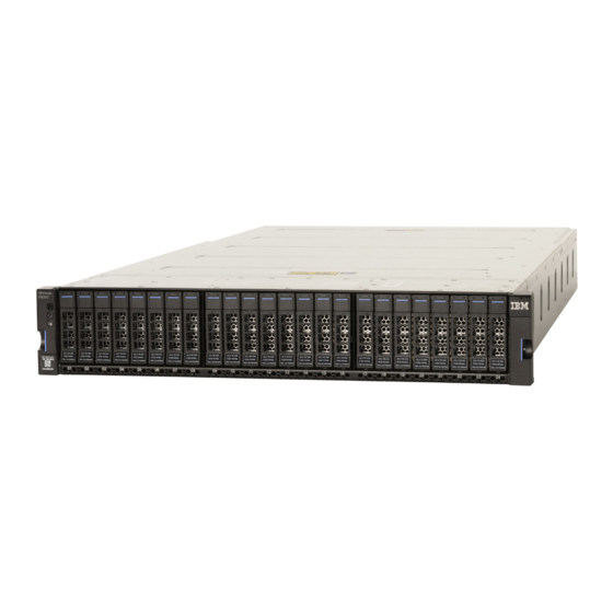
__ • Drives __ • Power cords for connection to wall sockets Identifying the hardware components The following graphics identify hardware components and port locations for the control enclosures and expansion enclosures of the system. Control enclosure components The Storwize V5100 control enclosure contains two node canisters. A label on the control enclosure identifies each node canister and power supply unit (PSU). -
Page 30: Orientation Of Ports On Node Canister 2 (Bottom)
Figure 3. Orientation of ports on node canister 2 (bottom) Data ports Four 10 Gbps Ethernet ports on each node canister provide system management connections and iSCSI host connectivity. The onboard 10 Gbps Ethernet ports use RJ-45 connections, not optical connections. The 10 Gbps ports operate at 1 Gbps when connected to a 1 Gbps switch. -
Page 31: Rear View Of A 2077/2078-424 / 2077/2078-Af4 2077 Expansion Enclosure
Figure 4. Rear view of a 2077/2078-424 / 2077/2078-AF4 2077 expansion enclosure Figure 5 on page 7 shows the LEDs and SAS port locations from the rear view of an expansion canister. • LEDs • SAS ports Each canister has two SAS ports that are numbered 1 on the left and 2 on the right. Port 1 is used to connect to a SAS expansion port on a node canister or port 2 of another expansion canister. -
Page 32: Identifying Storwize V5100 Node Canisters
Figure 6. Expansion enclosure support rails Identifying Storwize V5100 node canisters The Storwize V5100 node canisters include hardware changes that significantly differ from earlier model node canisters. The differences help distinguish the types of node canisters. The main difference is that Storwize V5100 node canisters are not side by side in the control enclosure, but each is the full width (minus the width of both power supplies) and half the height of the control enclosure, sitting one above the other in an inverted orientation. -
Page 33: Verify Environmental Requirements
If you have not done the environmental planning for your system, see the " physical installation planning" topic in the IBM Knowledge Center for the product. Complete the planning tasks and worksheets before you install and initialize your system. - Page 34 • A system can support up to 1520 drives that are installed into control and expansion enclosures. Each enclosure requires 2U of rack space. • Each assembled enclosure weighs more than 36 kg. Provide sufficient space at the front of the rack for three persons to carry the enclosure safely.
-
Page 35: Chapter 2. Installing The System Hardware
4. Confirm the Call Home settings that you entered during the installation. 5. Configure licensed functions. 6. Create storage pools. At the completion of the setup wizard, the setup wizard creates storage arrays and assigns the MDisks to the storage pools. © Copyright IBM Corp. 2019... -
Page 36: Unpacking The Storwize V5100 Control Enclosure
After the installation and initial configuration of the hardware is complete, IBM strongly recommends that you check to see whether a later level of firmware and software is available and update to that level. Unpacking the Storwize V5100 control enclosure Before you unpack the Storwize V5100 control enclosure, ensure that you review and follow all related instructions. -
Page 37: Installing Support Rails For The Control Enclosures
Installing support rails for the control enclosures Before you install the control enclosure into the rack, you must first install the support rails for it. Procedure To install the support rails for the control enclosure, complete the following steps. 1. Locate the control enclosure rails, as shown in Figure 8 on page 13. The rail assembly consists of two rails that must be installed in the rack cabinet. -
Page 38: Installing A Storwize V5100 Control Enclosure
• Rack mounting screw hole 3. Ensure that the appropriate bracket pins are installed in the front and rear bracket of each rail. Each rail comes with four medium pins preinstalled (two in the front bracket and two in the rear bracket). -
Page 39: Removing Enclosure End Caps
Figure 10. Removing enclosure end caps 2. Align the enclosure with the front of the rack cabinet. 3. Slide the enclosure into the rack along the rails until the enclosure is fully inserted. See Figure 11 on page 15. Note: The rails are not designed to hold an enclosure that is partially inserted. The enclosure must always be in a fully inserted position. -
Page 40: Unpacking A 2U Expansion Enclosure
The left end cap has indicator windows that align with the status LEDs (light-emitting diodes) on the edge of the enclosure. a) Ensure that the serial number on the left end cap matches the serial number on the left flange ("ear") on the front of the enclosure. -
Page 41: Installing Support Rails For 2U Expansion Enclosures
Installing support rails for 2U expansion enclosures Before you install 2U expansion enclosures, you must first install support rails. Procedure To install the support rails, complete the following steps. 1. Locate the expansion enclosure rails (Figure 13 on page 17). The rail assembly consists of two rails that must be installed in the rack cabinet. -
Page 42: Hole Locations In The Front Of The Rack
Figure 14. Hole locations in the front of the rack • Upper rail mounting bracket pin • Lower rail mounting bracket pin • Rack mounting screw hole 5. Ensure that the appropriate bracket pins are installed in the front and rear bracket of each rail. Each rail comes with four medium pins preinstalled (two in the front bracket and two in the rear bracket). -
Page 43: Opening The Hinge Brackets
Figure 15. Opening the hinge brackets 7. Align the holes in the rail bracket with the holes on the front and rear rack cabinet flanges. Ensure that the rails are aligned on the inside of the rack cabinet. 8. On the rear of the rail, press the two bracket pins into the holes in the rack flanges. 9. -
Page 44: Installing An Optional 2U Sas Expansion Enclosure
Installing an optional 2U SAS expansion enclosure The 2U SAS expansion enclosures are installed in the same rack as the control enclosure. About this task CAUTION: • To lift and install the 2U SAS expansion enclosure into the rack requires at least two people. •... -
Page 45: Tray Containing Expansion Enclosure Parts
• Read and follow the safety notices and instructions, as described in “Safety notices and considerations: 2077-92F, 2077-A9F ” on page 23. • Read and follow the guidelines that are described in “Weight considerations: 5U SAS expansion enclosure” on page 27. •... -
Page 46: Packaging Materials
Figure 18. Packaging materials Enclosure Top of shipping box, folded back Foam protectors 4. With four or more persons, push the expansion enclosure sideways onto an adjacent flat bed lift. Keep the remaining foam block protectors attached to the enclosure. 5. -
Page 47: Installing An Optional 5U Sas Expansion Enclosure
1U fascia (power supply units) 7. Remove the cable management arm assembly from its packaging ( in Figure 17 on page 21). Installing an optional 5U SAS expansion enclosure Before you install the optional 5U SAS expansion enclosure, review the following guidelines: The expansion enclosure is supported on Storwize V7000 2076-724 and 2077-424 systems that have Spectrum Virtualize 8.2.0 or later with the latest fix packs. - Page 48 DANGER: Observe the following precautions when working on or around your IT rack system: • Heavy equipment–personal injury or equipment damage might result if mishandled. • Always lower the leveling pads on the rack cabinet. • Always install stabilizer brackets on the rack cabinet. •...
- Page 49 • If the rack cabinet you are relocating is part of a suite of rack cabinets, detach the rack cabinet from the suite. • If the rack cabinet you are relocating was supplied with removable outriggers they must be reinstalled before the cabinet is relocated. •...
- Page 50 CAUTION: To avoid personal injury, before lifting this unit, remove all appropriate subassemblies per instructions to reduce the system weight. (C012) CAUTION: CAUTION regarding IBM provided VENDOR LIFT TOOL: • Operation of LIFT TOOL by authorized personnel only • LIFT TOOL intended for use to assist, lift, install, remove units (load) up into rack elevations. It is not to be used loaded transporting over major ramps nor as a replacement for such designated tools like pallet jacks, walkies, fork trucks and such related relocation practices.
-
Page 51: Weight Considerations: 5U Sas Expansion Enclosure
• Do not operate while under the influence of drugs or alcohol. • Do not support ladder against LIFT TOOL. • Tipping hazard. Do not push or lean against load with raised platform. • Do not use as a personnel lifting platform or step. No riders. •... -
Page 52: Weight Of Expansion Enclosure Parts
• At least three persons are required to move the enclosure while it is in the rack (if you are moving the enclosure off the rails). Even after the drives, power supply units, secondary expander modules, canisters, fans, and top cover are removed, the enclosure weighs approximately 43 kg (95 lbs). •... -
Page 53: Weight Of An Enclosure With 92 Sas Drives
Table 8. Weight of expansion enclosure parts (continued) Weight per unit Total weight FRU part Quantity description number shipped Fan interface 01LJ134 0.118 0.260 0.236 0.260 board Weight of expansion enclosure SAS drives The SAS drives are shipped in a separate package from the 5U expansion enclosure. The enclosure can support up to 92 SAS drives;... - Page 54 Table 10. Enclosure weight as FRUs are installed (continued) Enclosure assembly Approximate weight FRUs installed FRUs not installed 44.3 97.7 • Enclosure (01LJ607 or • Fascia (1U and 4U) 01LJ112) • PSUs • Secondary expansion • Expansion canisters modules • Fan modules •...
- Page 55 Table 10. Enclosure weight as FRUs are installed (continued) Enclosure assembly Approximate weight FRUs installed FRUs not installed 78.6 173.3 • Enclosure (01LJ607 or • Cover 01LJ112) • Secondary expansion modules • Fascia (1U and 4U) • PSUs • Expansion canisters •...
-
Page 56: Identify The Hardware Components: 2077-92F, 2077-A9F
Identify the hardware components: 2077-92F, 2077-A9F You should become familiar with the external components of the 2077-92F, 2077-A9F expansion enclosure. Components on the front of the enclosure Figure 20 on page 32 shows the front of the 2077-92F, 2077-A9F expansion enclosure. In the figure, all parts are installed in the enclosure. -
Page 57: Features On The Rear Of The 2077-92F, 2077-A9F Expansion Enclosure
Figure 21. Front fascia of the 2077-92F, 2077-A9F expansion enclosure Components on the rear of the enclosure Figure 22 on page 33 shows the components on the rear of the 2077-92F, 2077-A9F expansion enclosure. Four fan modules and two expansion enclosures are accessible from the back of the enclosure. Figure 22. - Page 58 Expansion canister SAS ports and indicators Expansion canister indicators Power cable connector for PSU 1 Support rails Figure 23 on page 34 shows the support rails for the expansion enclosure. The support rails are packaged separately from the expansion enclosure. Figure 23.
-
Page 59: Unpacking And Installing The Enclosure: 2077-92F, 2077-A9F
Figure 24. 2077-92F, 2077-A9F CMA assemblies Unpacking and installing the enclosure: 2077-92F, 2077-A9F Before you unpack and install the 2077-92F, 2077-A9F expansion enclosure, ensure that you review and follow the installation checklist and safety notices. Before you begin CAUTION: The weight of this part or unit is more than 55 kg (121.2 lb). It takes specially trained persons, a lifting device, or both to safely lift this part or unit. -
Page 60: Tray Containing Expansion Enclosure Parts
About this task The 2077-92F, 2077-A9F expansion enclosure and most parts are shipped together in one large box. A tray on the top of the enclosure contains the front fascia (1U and 4U pieces), the cable management arm (CMA), and the slide rail kit; you must install these parts. Figure 25 on page 36 shows how the enclosure is packaged for shipment. -
Page 61: Packaging Materials
Figure 26. Packaging materials Enclosure Top of shipping box, folded back. Foam protectors 4. Remove the top cover, as described in “Removing the top cover: 2077-92F, 2077-A9F ” on page 38. 5. With two or more persons, push the expansion enclosure sideways onto an adjacent flat bed lift. Keep the remaining foam block protectors attached to the enclosure. -
Page 62: Removing The Top Cover: 2077-92F, 2077-A9F
Figure 27. Packaging for fascia 4U fascia (front) 1U fascia (power supply units) 12. Attach the 4U and 1U fascia to the front of the enclosure, as described in “Installing or replacing the fascia: 2077-92F, 2077-A9F ” on page 43. 13. -
Page 63: Installing The Support Rails: 2077-92F, 2077-A9F
Procedure 1. Slide the release latch ( ) in the direction that is shown in Figure 28 on page 39. Figure 28. Releasing the 5U expansion enclosure cover 2. Slide the cover toward the front of the expansion enclosure ( ), as shown in Figure 28 on page 39. -
Page 64: Support Rails
Figure 30. Support rails 2. Select an available 5U space in your rack to install the expansion enclosure. Important notes: • When you select a rack location, ensure that the enclosure and its parts are easily accessible. Allow enough space for the lid to be easily removed and for internal components, such as drives and secondary expansion modules, to be serviced. -
Page 65: Screw Locations To Attach The Inner Rail To The Enclosure
Figure 32. Screw locations to attach the inner rail to the enclosure 5. Install the inner section of the rail onto each side of the expansion enclosure, as shown in Figure 33 on page 41. Figure 33. Attaching the inner rail section to the enclosure 6. -
Page 66: Installing The Rail Assembly To The Rack Frame
Figure 34. Installing the rail assembly to the rack frame For example, Figure 35 on page 42 shows the front of the rail that is attached to the frame. Figure 35. Example of the required rack space 42 Storwize V5100 : Quick Installation Guide for MTM 2078-424, 2078-12F, 2078-24F, 2078-92F, and 2078-... -
Page 67: Installing Or Replacing The Fascia: 2077-92F, 2077-A9F
7. Repeat steps “5” on page 41 through “6” on page 41 to install the opposite rail. 8. Install the expansion enclosure in the rack, as described in “Installing an optional 5U SAS expansion enclosure” on page 49. Installing or replacing the fascia: 2077-92F, 2077-A9F During the initial installation process or after you perform service, you can install the fascia components on the front of a 2077-92F, 2077-A9F expansion enclosure. -
Page 68: Installing Or Replacing A Drive: 2077-92F, 2077-A9F
Align the tab on each side of the 1U fascia with the corresponding slots on the enclosure flange. Pins on each flange must also align with a hole in each side of the 1U fascia. Figure 37. Replace fascia components on the expansion enclosure Installing or replacing a drive: 2077-92F, 2077-A9F Use the following procedure to install a drive for the first time or to replace a faulty drive in a 2077-92F, 2077-A9F expansion enclosure with a new one received from FRU stock. -
Page 69: Drive Assembly
About this task The 2077-92F, 2077-A9F expansion enclosure supports 92 drives. Figure 38 on page 45 shows an example of a drive assembly. Figure 38. Drive assembly Disk drive Online indicator Fault indicator Release latch Drive latch toes Drive carrier Procedure 1. -
Page 70: Correct Drive Installation
The drive slots must be populated sequentially, starting from the back-left corner position (slot 1, grid A1). Sequentially install the drive in the slots from left to right and back row to front. Always complete a full row before you install drives in the next row. For example, in Figure 40 on page 46, the drives are installed correctly. -
Page 71: Replace The Drive
Figure 42. Replace the drive 8. Rotate the handle down to lock the drive assembly into the chassis ( in Figure 42 on page 47). 9. Ensure the toe on the bottom of the latch is fully engaged with the partition in the chassis. 10. -
Page 72: Installing Or Replacing The Top Cover: 2077-92F, 2077-A9F
12. Replace the cover, as described in “Installing or replacing the top cover: 2077-92F, 2077-A9F ” on page 48. 13. Slide the expansion enclosure back into the rack, as described in “Installing an optional 5U SAS expansion enclosure” on page 49. Installing or replacing the top cover: 2077-92F, 2077-A9F You can replace the top cover on a 2077-92F, 2077-A9F expansion enclosure during the installation process or after you complete a service task. -
Page 73: Installing An Optional 5U Sas Expansion Enclosure
Figure 44. Replacing the 2077-92F, 2077-A9F top cover 4. Verify that the cover correctly engages the cover release latch and all of the inset tabs on the expansion enclosure. 5. Lock the cover into position by sliding the release lever , as shown in Figure 45 on page 49 Figure 45. -
Page 74: Example Installation Of The Enclosure In The Rack
Figure 46. Example installation of the enclosure in the rack • Ensure that the drives are easily accessible. Avoid installing the 2077-92F, 2077-A9F expansion enclosure above position 22U in the rack. If you are reinstalling the expansion enclosure in the rack after you performed a service task (for example, replacing the enclosure), you must also perform the following tasks: •... -
Page 75: Installing Or Replacing The Cable-Management Arm: 2077-92F, 2077-A9F
Figure 47. Replacing the 2077-92F, 2077-A9F enclosure in the rack 2. Ensure that the ball bearing retainer clicks into place inside the front of the left and right drawer sections ( in Figure 47 on page 51). Reinstalling parts into the enclosure 3. -
Page 76: Upper And Lower Cable-Management Arms
Figure 48. Upper and lower cable-management arms As Figure 49 on page 52 shows, the support rail connectors of each CMA assembly are installed on the rail hooks at the end of the support rails. Figure 49. Upper and lower cable-management arms Procedure 1. -
Page 77: Install The Inner Connector Of The Upper Cma To The Inner Member Of The Support Rail
Figure 50. Connectors for the cable management arm Inner connector on upper CMA Connector base on inner rail member Outer connector on upper CMA Connector base on outer rail member Support rail connector on upper CMA Connector base on outer rail member 2. -
Page 78: Attach The Support Rail Connector Of The Upper Cma To The Right Support Rail
4. Attach the support rail connector on the upper CMA assembly ( ) to the connector base on the right support rail ( ), as shown in Figure 53 on page 54. Figure 53. Attach the support rail connector of the upper CMA to the right support rail Ensure the cable-management arm connector attaches securely to the hooks on the rails. -
Page 79: Removing And Installing A Sas Cable: 2077-92F, 2077-A9F
6. Install the outer connector of the lower CMA assembly ( ) to the outer member of the right support rail , as shown in Figure 54 on page 54. 7. Attach the support rail connector on the lower CMA assembly ( ) to the connector on the left support rail ( ), as shown in Figure 54 on page 54. -
Page 80: Correct Orientation For Sas Cable Connectors
Blue pull tab SAS cable SAS port Figure 55. Correct orientation for SAS cable connectors 6. Insert the SAS cable into the SAS port until you hear or feel a click. When the cable is successfully inserted, you cannot disconnect the cable without pulling on the blue tag. Connecting to a Storwize V5100 node 7. -
Page 81: Connecting Optional Sas Expansion Enclosures: 2078-92F, 2078-A9F
Note: When you insert SAS cables, ensure that the connector is oriented correctly to the control enclosure and expansion enclosure. • For systems, IBM Storwize V5100 control enclosures, and 2077-24F 2U expansion enclosures, the blue pull tab must be below the cable ( in Figure 58 on page 57). -
Page 82: Connecting The Sas Cables
• For 2078-92F, 2078-A9F 5U expansion enclosures, the blue pull tab must be above the connector ( in Figure 58 on page 57). • Insert the connector gently until it clicks into place. If you feel resistance, the connector is probably oriented the wrong way. -
Page 83: Powering On The 2077-92F, 2077-A9F Expansion Enclosure
Table 11. Examples of supported SAS chain combinations 2077/2078-12F 2077-24F Enclosures 2078-92F, 2078-A9F Combined chain weight Enclosures Enclosures In addition, the orientation of the Input and Output SAS ports on the 2U and 5U SAS enclosures differs. Figure 60 on page 59 shows the SAS ports on the 2U and 5U expansion enclosures. Figure 60. -
Page 84: Features On The Front Of The 2077-92F, 2077-A9F Expansion Enclosure
About this task The 2077-92F, 2077-A9F expansion enclosure has two power supply units (PSUs) that are accessible from the front of the enclosure ( in Figure 61 on page 60). As the figure also shows, the PSUs are covered by the 1U fascia ( Figure 61. -
Page 85: Secure Power Cables
Figure 62. Secure power cables Important: Always secure each power cable with a cable retainer and ensure that the cable is installed along one of the cable management arms. When secured, the power and SAS cables stay connected when you slide the expansion enclosure out of the rack to perform service tasks. Figure 63. -
Page 86: Powering Off The Expansion Enclosure: 2077-92F, 2077-A9F
Figure 64. Features on the rear of the 2077-92F, 2077-A9F expansion enclosure Power cable connector for PSU 2 Power cable retention clamps Fan module Fan release latch Fan fault indicator Expansion canister SAS ports and indicators Expansion canister indicators Power cable connector for PSU 1 4. -
Page 87: Storwize V5100 2078-92F, 2078-A9F Expansion Enclosure Leds And Indicators
3. Wait 5 minutes for all write data to be flushed to the drives. 4. Unplug both of the power cords from the rear of the expansion enclosure to remove all power from the enclosure. Storwize V5100 2078-92F, 2078-A9F expansion enclosure LEDs and indicators The 2078-92F, 2078-A9F (5U) expansion enclosure has several sets of LEDs that provide information about the overall status of the enclosure, power, drives, fans, canisters, and SAS connections. -
Page 88: Leds On The Front Of A Power Supply Unit
Table 12. Display panel LEDs (continued) Function Color Status Description Identify Blue Identifies the expansion enclosure; this LED is controlled by the system. Use the management GUI or service interface to identify an enclosure. The expansion enclosure is operating normally. Enclosure fault Amber The expansion enclosure... -
Page 89: Led Indicators On Drives
LEDs inside of the expansion enclosure Each of the drives and secondary expansion modules within the 2077-92F, 2077-A9F expansion enclosure has two LED indicators. To view the drives and secondary expansion modules, you must remove the cover of the enclosure, as described in “Removing the top cover: 2077-92F, 2077-A9F ” on page 38. -
Page 90: Led Indicators On Secondary Expansion Modules
Figure 68. LEDs on a secondary expansion module Online indicator Fault indicator Table 15 on page 66 describes the meaning of the LEDs on each secondary expansion module. Table 15. LED indicators on secondary expansion modules Function Color Status Description Power Green The secondary expansion... -
Page 91: Leds On The Back Of The Expansion Enclosure
Figure 69. LEDs on the back of the expansion enclosure The expansion enclosure has four fans. Each fan has one LED; for example, Figure 69 on page 67 shows the location of the LED ( ) for fan number four. When a fan is operating normally, the LED is not lit. If a fault is detected, the amber LED is lit. -
Page 92: Storwize V5100 5U Expansion Enclosure Parts
Table 16. Expansion canister and SAS port LEDs Name Color State Meaning Canister fault Amber Normal operation. A fault was detected. Flashing The expansion canister is being identified. A fault might or might not be detected. Canister status Green Canister is off. Normal operation. -
Page 93: Other Expansion Enclosure Parts
Table 17. Supported expansion enclosure SAS drives Description FRU part number Comments 600 GB 15 K disk drive 01LJ037 1.2 TB 10 K disk drive 01LJ038 1.8 TB 10 K disk drive 01LJ039 6 TB 7.2 K Near-Line SAS disk drive 01LJ040 8 TB 7.2 K Near-Line SAS disk drive 01LJ041... -
Page 94: Connecting The Components
Table 18. Other expansion enclosure parts (continued) FRU Part Number Description Comments 00AR439 6 m 12 Gb SAS Cable (mSAS HD) 01LJ114 Rail kit 01LJ116 Front fascia (4U front cover) 01LJ118 Display panel assembly 01LJ120 PSU fascia (1U cover) The fascia must be removed to access the power supply units. -
Page 95: Connecting Ethernet Cables To The Node Canisters
Fibre Channel SAN. Before you begin Refer to the "Planning" section of the IBM Knowledge Center for instructions on determining the number of required cables and their intended port locations. -
Page 96: Connecting Optional Expansion Enclosures To The Control Enclosure
Connecting optional expansion enclosures to the control enclosure If you have installed expansion enclosures in the rack, you must connect them to the control enclosure. About this task This task applies if you are installing one or more expansion enclosures. Each control enclosure in the system can manage two chains of expansion enclosures;... -
Page 97: Connecting The Sas Cables
Figure 72. Connecting the SAS cables 2. To add a second expansion enclosure chain to the control enclosure, use the supplied SAS cables to connect the control enclosure to the expansion enclosure at rack position 2. Refer to Figure 72 on page 73 for an example. -
Page 98: Sas Cable Connectors
• The orientation of the connector must match the orientation of the port before you push the connector into the port. The cable connector and socket are keyed, and it is important that you have proper alignment of the keys when the cable is inserted. Note: On Storwize V5100 control enclosures, node canister 1 is inverted from node canister 2. -
Page 99: Powering On The Optional 2U Sas Expansion Enclosures
Figure 74. Connecting the SAS cables Powering on the optional 2U SAS expansion enclosures After you install all the hardware components, power on the optional 2U SAS expansion enclosures and check their status. About this task Attention: Do not power on an expansion enclosure with any open bays or slots. •... -
Page 100: Powering On The 2077-92F, 2077-A9F Expansion Enclosure
Note: Each enclosure has two power supply units. To provide power failure redundancy, connect the two power cords to separate power circuits. 2. From the rear of the rack, check the LEDs on each expansion enclosure (see Figure 75 on page 76). Figure 75. -
Page 101: Features On The Front Of The 2077-92F, 2077-A9F Expansion Enclosure
Figure 76. Features on the front of the 2077-92F, 2077-A9F expansion enclosure Display panel LEDs Rack retention thumb screws Power supply unit LEDs Power supply units (PSUs) PSU fascia (1U) Front fascia (4U) Each PSU has a power supply connector and power cable, which are accessible from the back of the enclosure. -
Page 102: Secure Power Cables
Figure 77. Secure power cables Important: Always secure each power cable with a cable retainer and ensure that the cable is installed along one of the cable management arms. When secured, the power and SAS cables stay connected when you slide the expansion enclosure out of the rack to perform service tasks. Figure 78. -
Page 103: Powering On The System
Figure 79. Features on the rear of the 2077-92F, 2077-A9F expansion enclosure Power cable connector for PSU 2 Power cable retention clamps Fan module Fan release latch Fan fault indicator Expansion canister SAS ports and indicators Expansion canister indicators Power cable connector for PSU 1 4. - Page 104 3. Power on the control enclosure. Use the supplied power cords to connect both power supply units of the enclosure to their power sources. If the power sources have circuit breakers or switches, ensure that they are turned on. The enclosure does not have power switches.
-
Page 105: Chapter 3. Configuring The System
GUI pages. IBM supports higher versions of the browsers if the vendors do not remove or disable function that the product relies upon. For browser levels higher than the versions that are certified with the product, customer support accepts usage-related and defect-related service requests. - Page 106 f. Click OK to close Security Settings. g. Click Yes to confirm the change for the zone. h. Click OK to close Internet Options. i. Refresh your browser. For Microsoft Internet Explorer (IE) running on Microsoft Windows Server 2008, complete the following steps: a.
-
Page 107: Initializing The Control Enclosure
f. Refresh your browser. 3. Enable file download on IE 11 running on Windows 2012. a. In Internet Explorer, click Tools > Internet Options. b. On the Internet Options window, select the Security tab. c. On the Security tab, click the Internet zone. d. -
Page 108: Completing The Initial System Setup
FlashCopy or Remote Mirror licenses does not always match the quantity of externally virtualized storage licenses. c) If you already use IBM Storage Insights, log in to Storage Insights, select Add Storage System and register the new system by using the IP address. -
Page 109: Verify And Update The System Firmware And Software
Verify and update the system firmware and software After the installation and initial configuration of the hardware is complete, IBM strongly suggests that you check to see whether a later level of firmware and software is available, and update to that level. - Page 110 86 Storwize V5100 : Quick Installation Guide for MTM 2078-424, 2078-12F, 2078-24F, 2078-92F, and 2078-...
-
Page 111: Chapter 4. Adding An Expansion Enclosure To An Existing System
System -- Overview page. If this action does not appear, review the installation instructions to ensure the new enclosure is cabled correctly. You can also add a new enclosure by selecting Add Enclosure from the System Actions menu. 8. Continue to follow the on-screen instructions. © Copyright IBM Corp. 2019... - Page 112 88 Storwize V5100 : Quick Installation Guide for MTM 2078-424, 2078-12F, 2078-24F, 2078-92F, and 2078-...
-
Page 113: Chapter 5. Adding A Control Enclosure To An Existing System
The management GUI requires a supported web browser. (See “Checking your web browser settings for the management GUI” on page 81.) Note: You cannot add a second control enclosure to another IBM Storwize V5100 system. Procedure To add a control enclosure to an existing system, complete the following steps. - Page 114 90 Storwize V5100 : Quick Installation Guide for MTM 2078-424, 2078-12F, 2078-24F, 2078-92F, and 2078-...
-
Page 115: Appendix A. Accessibility Features For The System
See your browser or screen-reader software Help for a list of keyboard shortcuts that it supports. IBM and accessibility See the IBM Human Ability and Accessibility Center for more information about the commitment that IBM has to accessibility. ©... - Page 116 92 Storwize V5100 : Quick Installation Guide for MTM 2078-424, 2078-12F, 2078-24F, 2078-92F, and 2078-...
-
Page 117: Appendix B. Where To Find The Statement Of Limited Warranty
Appendix B. Where to find the Statement of Limited Warranty The Statement of Limited Warranty is available in both hardcopy format and in the Storwize V5100 IBM Knowledge Center. The Statement of Limited Warranty is included (in hardcopy form) with your product. It can also be ordered from IBM. - Page 118 94 Storwize V5100 : Quick Installation Guide for MTM 2078-424, 2078-12F, 2078-24F, 2078-92F, and 2078-...
-
Page 119: Appendix C. Control Enclosure Requirements
Attempting to move the drawer partially or completely out of the rack might cause the rack to become unstable or cause the drawer to fall out of the rack. (R001 part 2 of 2) © Copyright IBM Corp. 2019... -
Page 120: Power Specifications Per Power Supply
If there is less airflow, additional mechanisms are required to cool the enclosure. An appropriate IBM rack configuration would be the 7014-T42 IBM Rack Model T42, with standard rear door and feature code 6069 Front Door For 2.0 Meter Rack (High Perforation). -
Page 121: Temperature Requirements
• Airflow passes between drive carriers and through each enclosure. • Airflow for the upper 4U of the 5U enclosure enters the front, passes between the disk drives, and exits through the large fans in the rear of the enclosure. •... -
Page 122: Rack Space Requirements For The 2078-92F Models
Figure 81. Rack space requirements for the 2078-92F models The following table shows the rack space requirements for the control enclosure in tabular form. Table 22. Rack space requirements for the 2077-424 or 2078-U5B control enclosure Minimum rail length Maximum rail depth 685 mm (27 in.) 765 mm (30.1 in.) Additional space requirements... -
Page 123: Acoustical Declaration With Noise Hazard Notice
The noise emission level that is stated is the declared (upper limit) sound power level, in decibels, for a random sample of machines. All measurements are made in accordance with ISO 7779 and reported in conformance with ISO 9296. Acoustical Declaration with Noise Hazard Notice Figure 82 on page 99 indicates the declared noise emissions values in accordance with ISO 9296. - Page 124 100 Storwize V5100 : Quick Installation Guide for MTM 2078-424, 2078-12F, 2078-24F, 2078-92F, and 2078-...
-
Page 125: Appendix D. Sas Expansion Enclosure Requirements
(BTU/hr) 100 V to 240 V single phase AC 10A for 100V 764 W (2) at a frequency 764W 2607 6A for 240V of 50 Hz to 60 2077/2078-12F or 2077/2078-24F or 2077/2078-AFF © Copyright IBM Corp. 2019... -
Page 126: Power Consumption Examples Per Enclosure
Table 27. Power specifications per power supply (continued) Input power Maximum input Maximum Caloric value Model and type requirements current power output (BTU/hr) 12 A (x2 - per AC 200-240 inlet 2077-92F, 2077- V~ , redundancy) (nominal; +/- Requires an IEC 10% tolerant) C20 appliance 2400 W (2) - Page 127 Table 28. Power consumption examples per enclosure (continued) Model and type Configuration Total power consumption 1 enclosure with 24 10 K SAS 175 W drives 2077/2078-12F or 2077/2078-24F or 2077/2078-AFF 1 enclosure with 24 15 K SAS 234 W drives 2077/2078-12F or 2077/2078-24F or 2077/2078-AFF 1 enclosure with 12 7.2 K...
-
Page 128: Temperature Requirements
Table 28. Power consumption examples per enclosure (continued) Model and type Configuration Total power consumption 1 enclosure with 92 15 TB tier 1 748 W flash drives 2077-92F, 2077-A9F 2078-92F, 2078-A9F Each SAS expansion enclosure contains two PSUs for redundancy. The total power consumption values represent the total power that is drawn by both PSUs. -
Page 129: Physical Characteristics Of The Expansion Enclosures
Table 29. Temperature requirements (continued) Ambient Maximum wet bulb Environment Altitude Relative humidity temperature temperature 1°C to 50°C 8% to 80% Non-operating 27°C (80°F) (34°F to 122°F) noncondensing 1°C to 60°C 5% to 80% Storage -305 to 12192 m (34°F to 140°F) noncondensing (-1000 to 40000 ft) 29°C (84°F) -
Page 130: Rack Space Requirements For The 2077/2078-24F , 2077-92F, 2077-A9F And 2078-92F, 2078- A9F Expansion Enclosures
Table 30. Physical characteristics of the expansion enclosures (continued) Maximum weight Drive ready Fully Enclosure Height Width Depth (without configured drive (with drive modules) modules) 2077-92F, 2077-A9F 222.2 mm 483 mm 968 mm (38.1 67 kg (147.7 135 kg (297 (8.75 in.) (19.0 in.) in.) - Page 131 The following table shows the rack space requirements for the expansion enclosures in tabular form. Table 31. Rack space requirements for the 2077/2078-24F , 2077-92F, 2077-A9F and 2078-92F, 2078-A9F expansion enclosures Enclosure Minimum rail length Maximum rail depth 595 mm (23.4 in.) 795 mm (31.3 in.) 2077/2078-12F or 2077/2078-24F or...
-
Page 132: Drive Specifications
Supported drives for Storwize V5100 SAS expansion enclosures Table 33 on page 108 provides drive specifications for Storwize V5100 SAS expansion enclosures. All drives are dual-port and hot-swappable. Drives of the same form factor and connector type can be intermixed within an enclosure. Table 33. -
Page 133: Declared Noise Emissions For 2077-92F, 2077-A9F And 2078-92F, 2078-A9F Sas Expansion
IBM recommends that you consult with qualified experts in this field to determine whether you are in compliance with the applicable regulations. - Page 134 Table 37. Vibration testing results (continued) Vibration categories Test level Performance Shipping 0.3 g 2-200Hz Sine <=5 g Rotational vibration Normal operation performance Throughput loss for all drives of the same type measurements in enclosure with within performance profile. no external vibration. 110 Storwize V5100 : Quick Installation Guide for MTM 2078-424, 2078-12F, 2078-24F, 2078-92F, and 2078-...
-
Page 135: Notices
Consult your local IBM representative for information on the products and services currently available in your area. Any reference to an IBM product, program, or service is not intended to state or imply that only that IBM product, program, or service may be used. Any functionally equivalent product, program, or service that does not infringe any IBM intellectual property right may be used instead. -
Page 136: Trademarks
International Business Machines Corp., registered in many jurisdictions worldwide. Other product and service names might be trademarks of IBM or other companies. A current list of IBM trademarks is available on the web at Copyright and trademark information at www.ibm.com/legal/copytrade.shtml. -
Page 137: Homologation Statement
Contact an IBM representative or reseller for any questions. Electromagnetic compatibility notices The following Class A statements apply to IBM products and their features unless designated as electromagnetic compatibility (EMC) Class B in the feature information. When attaching a monitor to the equipment, you must use the designated monitor cable and any interference suppression devices that are supplied with the monitor. -
Page 138: Japan Electronics And Information Technology Industries Association (Jeita) Notice
Tel: 914-499-1900 Der verantwortliche Ansprechpartner des Herstellers in der EU ist: IBM Deutschland GmbH Technical Relations Europe, Abteilung M456 IBM-Allee 1, 71139 Ehningen, Germany Tel: +49 800 225 5426 e-mail: Halloibm@de.ibm.com Generelle Informationen: Das Gerät erfüllt die Schutzanforderungen nach EN 55024 und EN 55032 Klasse A. -
Page 139: Japan Voluntary Control Council For Interference (Vcci) Notice
Japan Voluntary Control Council for Interference (VCCI) Notice Korea Notice People's Republic of China Notice Russia Notice Taiwan Notice Notices 115... -
Page 140: United States Federal Communications Commission (Fcc) Notice
Properly shielded and grounded cables and connectors must be used in order to meet FCC emission limits. IBM is not responsible for any radio or television interference caused by using other than recommended cables and connectors, or by unauthorized changes or modifications to this equipment. -
Page 141: Index
Index Numerics 2077-92F, 2077-A9F homologation statement 113 cable-management arm 51 2077-92F, 2077-A9F 2078-92F, 2078-A9F replacing in rack 49 LEDs expansion enclosure 76 air flow 79 management GUI adding an expansion enclosure 87 browsers, See web browsers notices cable-management arm environmental xix replacing 51 comments xxii configuration... - Page 142 specifications (continued) vibration 99 static-sensitive devices xix Storwize V5100 acoustic output of drives 98, 99 additional space requirements 98 air temperature without redundant AC power 96 dimensions and weight 97 enclosures acoustic output 98, 99 humidity without redundant AC power 96 power requirements for each PSU 96 weight and dimensions 97 technician port 83...
- Page 144 IBM® Part Number: 02YC382...