Kyocera Mita FS-C5016N Operation Manual
Hide thumbs
Also See for FS-C5016N:
- Operation manual (218 pages) ,
- Service manual (172 pages) ,
- Quick reference manual (44 pages)
Table of Contents
Advertisement
Quick Links
Advertisement
Table of Contents

Related Manuals for Kyocera Mita FS-C5016N


Summary of Contents for Kyocera Mita FS-C5016N
-
Page 1: Operation Guide
FS-C5016N Color Page Printer Operation Guide... - Page 2 Please read the Operation Guide before using the printer. Keep it close to the printer for easy reference. The sections of this guide and parts of the printer marked with symbols are safety warnings meant to protect the user, other individuals and surrounding objects, and ensure correct and safe usage of the printer. The symbols and their meanings are indicated below.
- Page 3 This Kyocera Mita page printer uses PeerlessPrintXL to provide the HP LaserJet compatible PCL 6 language emula- tion. PeerlessPrintXL is a trademark of The Peerless Group, Redondo Beach, CA 90278, U.S.A.
- Page 4 IBM PROGRAM LICENSE AGREEMENT THE DEVICE YOU HAVE PURCHASED CONTAINS ONE OR MORE SOFTWARE PROGRAMS ("PRO- GRAMS") WHICH BELONG TO INTERNATIONAL BUSINESS MACHINES CORPORATION ("IBM"). THIS DOCUMENT DEFINES THE TERMS AND CONDITIONS UNDER WHICH THE SOFTWARE IS BEING LICENSED TO YOU BY IBM. IF YOU DO NOT AGREE WITH THE TERMS AND CONDITIONS OF THIS LICENSE, THEN WITHIN 14 DAYS AFTER YOUR ACQUISITION OF THE DEVICE YOU MAY RETURN THE DEVICE FOR A FULL REFUND.
- Page 5 Agfa Monotype License Agreement 1) "Software" shall mean the digitally encoded, machine readable, scalable outline data as encoded in a special format as well as the UFST Software. 2) You agree to accept a non-exclusive license to use the Software to reproduce and display weights, styles and versions of letters, numerals, characters and symbols ("Typefaces") solely for your own customary business or personal purposes at the address stated on the registration card you return to Agfa Japan.
- Page 6 FCC statement (for users in the United States) This device complies with Part 15 of the FCC Rules. Operation is subject to the following two conditions: (1) This device may not cause harmful interference, and (2) this device must accept any interference received, including inter- ference that may cause undesired operation.
- Page 7 Important Notes for Interface connectors Be sure to power off the printer before connecting or disconnecting an interface cable. For protection against static electricity discharge to the printer's internal electronics through the interface connector(s), cover any interface connec- tor that is not in use with the protective cap supplied. Use shielded interface cables.
- Page 8 Declaration of Conformity for U.S.A. Model name: Color Page Printer FS-C5016N Trade name: Kyocera Mita Responsible party: Kyocera Mita America, Inc. Address: 225 Sand Road PO Box 40008 Fairfield, New Jersey 07004-0008, U.S.A. Telephone: (973) 808-8444 Fax: (973) 882-6000 Manufacturer: Kyocera Mita Corporation Tamaki Plant Manufacturer’s address: 704-19, Nojino, Tamaki-cho, Watarai-gun, Mie-ken 519-0497, Japan...
- Page 9 Disclaimer Kyocera Mita will not be liable to customers or any other person or entity for any loss or damage caused or alleged to be caused directly or indirectly by equipment sold or furnished by us, including but not limited to, any interruption of service, loss of business or anticipatory profits, or consequential damages resulting from the use or operation of the equipment or software.
- Page 10 ® NERGY As an E Partner, we have determined that this product meets the E NERGY NERGY guidelines for energy efficiency. The basic objective of the E Program is to reduce environmental pollution by NERGY encouraging the manufacture and sale of equipment that uses energy more efficiently. This printer is equipped with a sleep timer function that conforms with the standards of the E Program.
-
Page 11: Installation Precautions
Installation Precautions Environment CAUTION • Avoid placing the printer on or in locations which are unstable or not level. Such locations may cause the printer to fall down or fall over. This type of situation presents a danger of personal injury or damage to the printer. - Page 12 Power Supply/Grounding the Printer WARNING • DO NOT use a power supply with a voltage other than that specified. Avoid multiple connec- tions in the same outlet. These types of situations present a danger of fire or electrical shock... • Plug the power cord securely into the outlet. If metallic objects come in contact with the prongs on the plug, it may cause a fire or electric shock.
-
Page 13: Precautions For Use
Precautions for Use Cautions when Using the Printer WARNING • DO NOT place metallic objects or containers with water (flower vases, flower pots, cups, etc.) on or near the printer. This type of situation presents a danger of fire or electrical shock should they fall inside. - Page 14 Other Precautions • DO NOT place heavy objects on the printer or cause other damage to the printer. • DO NOT open the top cover, turn off the main switch, or pull out the power plug during printing. • During printing, some ozone is released, but the amount does not cause any ill effect to one's health.
-
Page 15: For More Information
KX Printer Drivers Operation Guide Describes how to install and set the printer driver. PRESCRIBE Command Technical PRESCRIBE is the native language of the Kyocera Mita Reference printers. This Technical Reference contains the information about how the printing is performed using the PRESCRIBE commands as well as the font and emulation description. -
Page 16: Table Of Contents
Contents Contents Chapter 1 Introduction Features ..........1-2 1.1.1 General . - Page 17 Contents 3.6.1 Default Emulation ........3-42 3.6.2 Alternative Emulation for KPDL Emulation .
- Page 18 Contents 4.4.4 Jam at the Paper Transfer Unit ......4-15 4.4.5 Jam at the Rear Cover ........4-16 4.4.6 Jam at the MP Tray .
-
Page 19: Chapter 1 Introduction
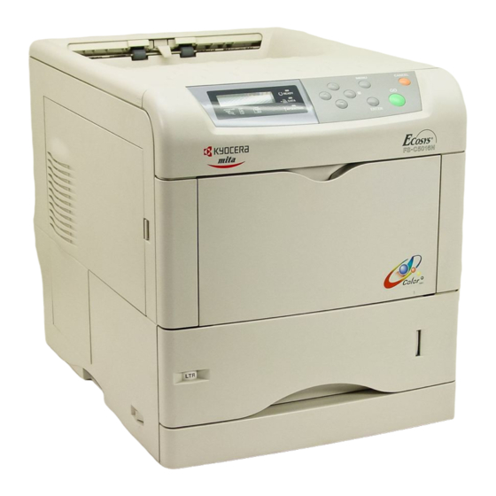
Welcome to the professional color printer from Kyocera Mita. With the Ecosys Color FS-C5016N, you can print out color or monochrome pages at a speed of 16 pages per minute (A4 size) or 17 pages per minute (Letter and A5 sizes). -
Page 20: Features
1.1 Features Features This section outlines the common major printer features of the FS-C5016N Ecosys color page printer. 1.1.1 General Components with an ultra-long product life The main printer components such as the Advanced Beam Array, imaging drum, development units, and fuser unit have an ultra-long product life. -
Page 21: Software
Printer control language PRESCRIBE The printer uses PRESCRIBE, Kyocera Mita’s page printer control language with enhanced color graphics capabilities. The simple commands of PRESCRIBE allow the programmers to easily define pagination and device control. -
Page 22: Networking
1.1 Features KPDL3 (Kyocera Printer Description Language 3) KPDL3 is the Kyocera’s implementation of the PostScript page description language Level 3. The printer has 136 fonts that are compatible with Adobe PostScript fonts. (The printer also has 80 PCL fonts.) PDF direct printing Allows you to send a selected PDF file directly to the printer without invoking a printer driver. -
Page 23: Parts And Functions
1.2 Parts and Functions Parts and Functions This section provides explanations and illustrations for you to determine the parts and their functions. Try to be familiar with the names and functions of these parts for correct use and optimal performance. 1.2.1 Front Figure 1-1... -
Page 24: Left
1.2 Parts and Functions 1.2.2 Left Figure 1-2 Face-down Tray This tray receives printouts face down. Power Switch This switch turns printer power on and off. Left Cover This cover needs to be opened when replacing the waste toner box or cleaning the main charger units. -
Page 25: Internal
1.2 Parts and Functions 1.2.3 Internal Figure 1-3 Magenta Toner Container This container holds magenta (M) toner. You must replace the container when the toner run out. Cyan Toner Container This container holds cyan (C) toner. You must replace the container when the toner run out. -
Page 26: Rear
1.2 Parts and Functions 1.2.4 Rear Figure 1-4 Vents Air is purged through these vents to cool down the inside. USB Interface Connector This connector is a USB interface that conforms to the Full-Speed USB 2.0. Use a USB cable between this connector and the USB port on a computer. Memory Card Slot This slot receives a memory card. -
Page 27: Chapter 2 Handling Paper
Chapter 2 Handling Paper The printer can use a variety of media in various sizes. However, any media you will choose to use with the printer must be in accordance with the guidelines and specifications in this chapter. Use of paper not satisfying these guidelines and specifications may cause problems such as frequent paper jams, poor quality printing, and possible damage to the printer mechanism. -
Page 28: General
Note 2.1.1 Available paper types The FS-C5016N printer can use almost any type of printer paper. This printer accepts paper used for xerographic copiers as well. Paper comes in three generic grades: economy, standard, and premium. The grades are determined by how easily the paper can pass through the printer. This depends on the smoothness, size, moisture content, and cutting of the paper. -
Page 29: Minimum And Maximum Paper Sizes
2.1 General Item Values Direction of grain Long grain Pulp content 80 % or more Table 2-1 (Continued) 2.1.3 Minimum and Maximum Paper Sizes The minimum and maximum paper sizes are as follows. For non standard paper such as cut-sheet, the MP (multi-purpose) tray must be used. Paper cassette MP tray Minimum... -
Page 30: Selecting The Right Paper
2.2 Selecting the Right Paper Selecting the Right Paper Printer printing is a process involving light, electrostatic discharge, toner, and heat. In addition, as the paper passes through the printer it undergoes considerable sliding, bending, and twisting motions. A high-quality printing paper matching the printer's requirements with-stands all these stresses, enabling the printer to turn out clean, crisp printed copy consistently. -
Page 31: Paper Properties
2.2 Selecting the Right Paper MP tray Size Cassette or Size MP tray Hagaki 10 × 14.8 cm Oficio II 8-1/2 × 13 inches Ofuku-Hagaki 14.8 × 20 cm Folio 21 × 33 cm Youkei 2 11.4 × 16.2 cm 16 kai 19.7 cm ×... -
Page 32: Moisture Content
2.2 Selecting the Right Paper U. S. Bond Weight (lb) Europe Metric Weight (g/m²) Table 2-4 (Continued) Thickness (Caliper) Thick paper is called high-caliper paper and thin paper is called low-caliper paper. Paper used by the printer should be neither too thick nor too thin. If you encounter paper jam, multiple-sheet feed, or too light printing problems, the paper may be too thin. -
Page 33: Other Properties Of Paper
2.2 Selecting the Right Paper 2.2.3 Other properties of paper Porosity The density of paper structure, which indicates the compactness of the fiber bonding. It is also the characteristic that allows air to pass through paper (i.e., air permeability). Stiffness The ability of paper to resist deformation under stress. -
Page 34: Loading Paper
2.3 Loading Paper Loading Paper The following explains the procedure for loading paper in the cassette and the MP tray. Fan the media (paper/transparencies), then tap it on a level surface to avoid media jams or skewed printing. Caution Figure 2-2 2.3.1 Loading Paper into the Cassette Perform the following procedure to load paper into the cassette. - Page 35 2.3 Loading Paper Push the bottom plate down until it locks. Bottom Plate Figure 2-4 Standard paper sizes are attached to the inside of the paper cassette as shown in the following figure. Figure 2-5...
- Page 36 2.3 Loading Paper Turn the paper size dial so that the size of the paper you are going to use appears in the paper size window. Paper Size Dial Paper Size Window Figure 2-6 When the paper size dial is set to OTHER the paper size must be set into the printer on the operator panel.
- Page 37 2.3 Loading Paper Adjust the position of the paper stopper located at the rear of the paper cassette. Pull the release lever and slide the paper stopper to the desired paper size. When shipped from the factory, the paper cassette is set to A4 size. When using non-standard size paper, move the paper guides and paper stopper all the way out, insert the paper, then adjust the paper guides and paper stopper to the size of the paper.
- Page 38 2.3 Loading Paper • Do not load more paper than will fit under the load limits on the paper guides. Note • The paper cassette will hold approximately 500 sheets of paper with a 80 g/m² (21 lb.) basis weight, or with a thickness of 0.11 Load Limit Load Limit Figure 2-10...
- Page 39 2.3 Loading Paper Insert the paper cassette into the slot in the printer. Push it straight in as far as it will Figure 2-12 There is a paper gauge on the right side of the front of the paper cassette to indicate the remaining paper supply.
-
Page 40: Loading Paper Into The Mp (Multi-Purpose) Tray
2.3 Loading Paper 2.3.2 Loading Paper into the MP (Multi-Purpose) Tray Perform the following procedure to load paper into the MP tray. Pull the MP tray towards you until it stops. MP Tray Figure 2-14 Pull out the subtray. Subtray Figure 2-15 Adjust the position of the paper guides on the MP tray. - Page 41 2.3 Loading Paper Align the paper with the paper guides and insert as far as it will go. Load Limit Load Limit Figure 2-17 • Do not load more paper than will fit under the load limits on the inside of the MP tray.
-
Page 42: Special Paper
Before purchasing any special paper, make a test print using the printer and check whether the results are satisfactory. Kyocera Mita shall not be liable for any danger to a person or machine that is caused by using special paper (e.g., fumes emitted from the special paper). - Page 43 2.4 Special Paper Transparency Transparencies for overhead projectors must withstand the heat of fusing during the printing process. The recommended transparency product is as follows: 3M CG3700 (Letter, A4) Transparencies must be placed on the MP (multi-purpose) tray with the long edge towards the printer.
- Page 44 2.4 Special Paper When the label paper has extra margin around the label’s outside edges that correspond to the margins of the printable area, do not remove the extra top sheet from the carrier sheet until printing is finished. Allowed Not allowed Top sheet Carrier sheet...
-
Page 45: Thick Paper
2.4 Special Paper Envelopes Envelopes should be fed in the face-up position, right edge first. Figure 2-22 Since the composition of an envelope is more complex than that of ordinary paper, it is not always possible to ensure consistent printing quality over the entire envelope surface. Normally, envelopes have a diagonal grain direction. -
Page 46: Colored Paper
2.4 Special Paper Colored paper Colored paper should have the same specifications as the white bond paper listed. In addition, the pigments in the paper must be able to withstand the heat of fusing during the printing process (up to 200 °C or 392 °F). Pre-printed paper Pre-printed paper should basically be bond paper. -
Page 47: Paper Type
2.5 Paper Type Paper Type The printer is capable of printing under the optimum setting for the type of paper being used. Setting the paper type for the paper source from the printer’s operator panel will cause the printer to automatically select the paper source and print in the mode best suited to that type of paper. -
Page 48: Chapter 3 Using The Operator Panel
Note You can also rely on other printer utilities such as Kyocera Mita PrintMonitor if you need to change settings that are not available on the printer driver. It will allow you remotely access to printer settings. -
Page 49: Understanding The Operator Panel
3.1 Understanding the Operator Panel Understanding the Operator Panel The operator panel on the top of the printer has a 2-line by 16-character liquid crystal display (LCD), eight keys, and three indicators (LED). MENU CANCEL READY DATA INTERFACE SIZE TYPE ATTENTION ENTER Figure 3-1... -
Page 50: Indicators In Message Display
3.1 Understanding the Operator Panel Message Meaning The printer is in sleep mode. The printer wakes from sleep mode Sleeping whenever a key on the operator panel is pressed, the cover is opened or closed, or a print job is received. The printer then warms up and goes on-line. - Page 51 3.1 Understanding the Operator Panel Paper Size Indicator (SIZE) This indicator indicates: • While the printer is in standby, the paper size of the current cassette. The default paper cassette is determined by the operator panel keys. For details, see section 3.10 Paper Handling on page 3-68.
- Page 52 3.1 Understanding the Operator Panel Paper Type Indicator (TYPE) This indicator shows the paper type defined for the current paper casette. The paper type can be manually defined using the operator panel. For more information, see section 3.10 Paper Handling on page 3-68.
-
Page 53: Keys
3.1 Understanding the Operator Panel 3.1.3 Keys The operator panel keys are used to configure the printer operation. Note that certain keys have the secondary function. The printer has a parallel, serial, and an optional network interface. Configuration to the printer settings made with these keys affect only one of these interfaces that is currently active (indicated by the INTERFACE Note indicator on the message display). -
Page 54: Arrow Keys
3.1 Understanding the Operator Panel MENU Key MENU The MENU key lets you enter the menu system to change the setup and printing environment of the printer. Pressing this key during a menu selection will terminate the selection and return the printer to the normal operation. -
Page 55: Using The Menu Selection System
3.2 Using the Menu Selection System Using the Menu Selection System 3.2.1 Menu Selection System This section explains how to use the menu selection system. The MENU key on the operator panel allows you to use the menu to set or change the printer environment such as the number of copies to print, emulation, etc., to your specific needs. - Page 56 3.2 Using the Menu Selection System Selecting a Menu The mode selection menu is hierarchical. Press the key to display the desired menu. • If the selected menu has a sub-menu, > is displayed after the menu. Paper Handling > Indicates that there is a sub-menu Press the key to move to the sub-menu or...
-
Page 57: Menu System Road Map
3.2 Using the Menu Selection System 3.2.2 Menu System Road Map The following is the hierarchy diagram of the menu selection system of the printer. For details about menu selection operations, see page 3-8. Ready PAR A4 PLAIN MENU Key Print Menu Map Print... - Page 58 3.2 Using the Menu Selection System Continued Interface > >Parallel I/F Parallel Nibble (high) Interface Interface > >NetWare Network Interface > >NetWare > >>NetWare Frame Serial Auto Interface > Option >TCP/IP >TCP/IP > >>DHCP >>DHCP >EtherTalk >EtherTalk >>IP Address 000.000.000.000 >Network Status >>Subnet Mask Page...
- Page 59 3.2 Using the Menu Selection System Continued Font > >Font Select > >> I000 Internal >Font Select > Option >>Courier Regular >>Courier >Code Set Dark IBM PC-8 >>Letter Gothic Regular >>Letter Gothic >List of Dark Internal Fonts >>Size >List of 012.00 point(s) Option Fonts >>Pitch...
- Page 60 3.2 Using the Menu Selection System Continued Paper Handling > >MP Tray Mode Cassette >MP Tray Mode First >MP Tray Size >MP Tray Type Plain >Cassette Size >Cassette Size > >>Unit Custom >>Unit inch >Cassette Type Plain >>X Dimension 216 mm >Feed Select >>Y Dimension Cassette...
- Page 61 3.2 Using the Menu Selection System Continued Others > >MSG Language English >Form Feed Time Out 030sec. >Sleep Timer > >>Sleep Mode 015 min. >>Sleep Mode >Print HEX-DUMP >Printer Reset >Resource Prot. >Buzzer >Buzzer >Auto Continue Mode >Auto Continue > >>Auto Continue Mode Timer...
-
Page 62: Menu Map And Status Pages
3.3 Menu Map and Status Pages Menu Map and Status Pages This section explains the procedure for printing the printer’s internal information using the menu selection system. The menu map is usefull as a reference to guide yourself through the menu selection system. - Page 63 3.3 Menu Map and Status Pages FS-C5016N Page Printer MENU MAP Figure 3-3 3-16...
-
Page 64: Printing A Status Page
3.3 Menu Map and Status Pages 3.3.2 Printing a Status Page You can check the printer’s current status, including available memory space and option settings by printing a status page. Press the MENU key. Press the key repeatedly until Print Status Page appears. Print Status Page Press the ENTER key. -
Page 65: Understanding The Status Page
Understanding the Status Page The numbers in the following diagram refer the items explained below the diagram. The items and values on the status page may vary depending on the printer’s firmware version. FS-C5016N Page Printer STATUS PAGE Firmware Version:... - Page 66 3.3 Menu Map and Status Pages Memory This item shows: • Standard memory in the printer (96 MB) • Option memory slot status (Slots 1 and 2) in megabytes • Total memory in the printer • Current status of the RAM disk Page Information This item shows the page related items: •...
-
Page 67: E-Mps
3.4 e-MPS e-MPS e-MPS is an abbreviation for ‘enhanced-Multiple Printing System’ which implements the following functions that are available from the printer driver: • Job Retention • Job Storage In either job mode, when printing a document, the print data is transferred from the computer to the printer then stored on the printer’s hard disk. -
Page 68: Using Quick Copy
3.4 e-MPS Job Storage Job storage stores print jobs either temporarily or permanently, or in virtual mailboxes, as you click an appropriate radio button on the printer driver when printing from a computer. Virtual Mailbox Virtual mailbox is part of Job Storage, which stores print jobs on the hard disk without printing. -
Page 69: Quick Copy
3.4 e-MPS Printing Additional Copies using Quick Copy To print additional copies of a job stored in the printer: Press the MENU key. Press the key repeatedly until e-MPS > appears. e-MPS > Press the key. Press the key repeatedly until >Quick Copy appears followed by the user name (Harold, in this example). -
Page 70: Using Proof-And-Hold
3.4 e-MPS Deleting a Quick Copy Job All quick copy jobs are automatically deleted when the printer is turned off. If you desire to explicitly delete a stored quick copy job, proceed as follows: Follow steps 1 through 8 in the above section to let the title of the job to be deleted displayed. -
Page 71: Printing A Private Print/Stored Job
3.4 e-MPS 3.4.3 Printing a Private Print/Stored Job In private printing, you can specify that a job is not printed until you release the job from the operator panel. At sending the job from the application software, you can specify a 4-digit access code in the printer driver. - Page 72 3.4 e-MPS Press the ENTER key. The ID input line appears. Enter the four-digit access code entered in the printer driver and press the ENTER key. >Agenda 0000 To enter the ID, press the key to move the cursor to the number to be changed and then enter the correct number by pressing the key.
- Page 73 Install the KM-NET Job Manager software from the CD-ROM supplied with the printer. To do this, from the CD-ROM Main Menu, select Printer Utilities > Install KM-NET Job Manager. Browse through Windows Start > Programs > KYOCERA MITA > KM-Net > Job Manager. Enter the password for the software. Job Manager will start.
- Page 74 Press the ENTER key. A question mark (?) appears. >List of Code JOB ? Press the ENTER key again. The printer prints a Code Job list as shown in Figure 3-5 below. FS-C5016N Page Printer PERMANENT CODE JOB LIST Figure 3-5 3-27...
-
Page 75: Retrieving Jobs From Virtual Mailbox (Vmb)
3.4 e-MPS 3.4.4 Retrieving Jobs from Virtual Mailbox (VMB) To retrieve the jobs posted in the virtual mailbox, proceed as follows. Press the MENU key. Press the key repeatedly until e-MPS > appears. e-MPS > Press the key. Press the key repeatedly until >Print Data appears. - Page 76 Press the ENTER key. A question mark (?) appears. >List of VMB ? Press the ENTER key again. The printer prints a list of jobs currently posted in the virtual mailboxes as shown in Figure 3-6 below. FS-C5016N Page Printer VIRTUAL MAIL BOX LIST Figure 3-6 3-29...
-
Page 77: Changing E-Mps Configuration
3.4 e-MPS 3.4.5 Changing e-MPS Configuration You can change the following parameters for e-MPS operation: • Maximum number of Quick Copy/Proof-and-Hold jobs • Maximum space assigned to temporary code jobs • Maximum space assigned to permanent code jobs • Maximum space assigned to virtual mailboxes The total amount of storage areas specified must not exceed the total size of the hard disk. - Page 78 3.4 e-MPS Press the MENU key. The display returns to Ready. Maximum Space Assigned to Temporary Code Jobs This changes the hard disk space that holds temporary code jobs. You can change the maximum space from 0 to 9999 (megabytes). The actual maximum size depends on the size of free hard disk space, however.
- Page 79 3.4 e-MPS Maximum Space Assigned to Permanent Code Jobs This changes the hard disk space that holds permanent code jobs. You can change the maximum space from 0 to 9999 (megabytes). The actual maximum size depends on the size of free hard disk space, however. The default size is 1/6 of the total hard disk space, rounded off in unit of 50 MB.
- Page 80 3.4 e-MPS Maximum Space Assigned to Virtual Mailboxes (VMB) This changes the hard disk space for virtual mailboxes. You can change the maximum space from 0 to 9999 (megabytes). The actual maximum size depends on the size of free hard disk space, however.
-
Page 81: Changing The Interface Parameters
3.5 Changing the Interface Parameters Changing the Interface Parameters The printer is equipped with both a parallel and USB interfaces. Optional serial interface board kit and network interface card can also be installed. Various printing environment parameters such as the default emulation can be changed independently on different interfaces by using the printer’s menu selection system. -
Page 82: Changing Serial Interface Parameters
3.5 Changing the Interface Parameters To change the communication mode, press the ENTER key. A blinking question mark (?) appears. >Parallel I/F ? Nibble (high) Press the key to scroll through the following communication modes: Nibble (high) Auto Normal High Speed When the desired communication mode is displayed, press the ENTER key. -
Page 83: Baud Rate
3.5 Changing the Interface Parameters Pressing the key toggles through the serial parameters as follows. To change the serial parameter, press the ENTER key. Use the key to change the value or selection. Range 1200 2400 4800 9600 (Default), 19200 >Baud Rate 38400 57600... -
Page 84: Changing Network Interface Parameters
3.5 Changing the Interface Parameters 3.5.3 Changing Network Interface Parameters This printer supports TCP/IP, NetWare and EtherTalk protocols. In addition, you can install the optional network interface card in the option interface slot. Using the operator panel, you can: • Activate or deactivate TCP/IP, NetWare, and AppleTalk •... - Page 85 3.5 Changing the Interface Parameters Press the key. One of the following menus is indicated. To change settings for the item, press the ENTER key. Use the key to change the value or selection. Range Set this item to when you connect to a network >NetWare >...
-
Page 86: Resolving Ip Address
3.5 Changing the Interface Parameters 3.5.4 Resolving IP Address To connect the printer to the network using TCP/IP protocol, you must set the IP address on the printer. The IP address must be unique to the printer and should be obtained from your network administrator. - Page 87 3.5 Changing the Interface Parameters Printing a Network Interface Status Page You can have your printer print out a network status page when the printer prints the status page. The network status page shows the network addresses, and other information under various network protocols about the network interface card.
- Page 88 3.5 Changing the Interface Parameters Press the ENTER key again. Press the MENU key. The display returns to Ready. The printer prints a network status page as an example shown in Figure 3-7 below. FS-C5016N Page Printer NETWORK STATUS PAGE Figure 3-7 3-41...
-
Page 89: Making Default Settings
3.6 Making Default Settings Making Default Settings Using the operator panel, you can set the default for the following items. Note default settings made using the operator panel may be overridden by the printer driver settings and application software. 3.6.1 Default Emulation You can change the emulation mode and character code set for the current interface. -
Page 90: Alternative Emulation For Kpdl Emulation
3.6 Making Default Settings 3.6.2 Alternative Emulation for KPDL Emulation The auto KPDL [KPDL (AUTO)] emulation enables the printer to automatically change the emulation mode according to the print job received. The emulation mode the printer switches alternatively can be selected using the operator panel. The default alternative emulation is HP PCL 6. -
Page 91: Printing Kpdl Errors
3.6 Making Default Settings 3.6.3 Printing KPDL Errors The printer can print error descriptions when printing error occurs during KPDL emulation. The default is Off — the printer does not print KPDL errors. Press the MENU key. Press the key repeatedly until Emulation > appears. Emulation >... -
Page 92: Default Font
3.6 Making Default Settings 3.6.4 Default Font You can select the default font for the current interface. The default font can be one of the internal fonts or a font that is downloaded to the printer memory or stored on memory card or hard disk. - Page 93 3.6 Making Default Settings Selecting Regular or Dark Courier/Letter Gothic Courier or Letter Gothic font thickness can be selected as Regular or Dark. In the procedure below, it is assumed that Courier is selected. The procedure is the same for Letter Gothic.
- Page 94 3.6 Making Default Settings Changing the Default Font Size You can change the size of the default font. If you selected a proportional font, the character size can also be changed. Press the MENU key. Press the key repeatedly until Font > appears. Font >...
- Page 95 3.6 Making Default Settings Character Pitch for Courier/Letter Gothic You can set the character pitch for fixed fonts when the default font is Courier or Letter Gothic. Press MENU key. Press the key repeatedly until Font > appears. Font > Press the key.
-
Page 96: Code Set
3.6 Making Default Settings Setting the Code Set You can change the character code set. Available character code sets vary depending on the current font. (The default is IBM PC-8.) Press the MENU key. Press the key repeatedly until Font > appears. Font >... - Page 97 3.6 Making Default Settings Printing Lists of Fonts To help you decide in selecting a font, you can printout lists of the internal fonts or the optional fonts including downloaded fonts. Samples for font lists are shown in Figure 3-8 on page 3-51.
- Page 98 3.6 Making Default Settings Internal Scalable and Bitmapped Fonts List PRESCRIBE Font Name Scalable/Bitmap Password Selection [FSET] Font ID Internal Scalable and Bitmapped Fonts List PRESCRIBE Font Name Scalable/Bitmap Password Selection [FSET] Font ID Figure 3-8 3-51...
-
Page 99: Pagination
3.7 Pagination Pagination In Page Set menus, you can set the number of copies, page orientation, and other settings regarding pagination. 3.7.1 Number of Copies You can set the number of copies of each page to be printed for the current interface. The number of copies can be set between 1 and 999. -
Page 100: Print Orientation
3.7 Pagination 3.7.2 Print Orientation You can select portrait (upright) or landscape (sideways) page orientation. Portrait Orientation Landscape Orientation Figure 3-9 Press the MENU key. Press the key repeatedly until Page Set > appears. Page Set > Press the key. Press the key repeatedly until >Orientation appears. -
Page 101: Page Protect Mode
3.7 Pagination 3.7.3 Page Protect Mode The Page Protect Menu does not normally appear, however, Page Protect will be forcibly set to On if a print overrun error occurs because the print job is too complex. When this has happened, be sure to reset Page Protect to Auto (default) in order to maintain the optimum use of printer memory. -
Page 102: Linefeed (Lf) Action
3.7 Pagination 3.7.4 Linefeed (LF) Action This procedure instructs the printer what to do when it receives a linefeed code (0AH). • LF only: Linefeed is performed (Default). • CR and LF: A linefeed and carriage return are performed. • Ignore LF: The linefeed is ignored. -
Page 103: Carriage-Return (Cr) Action
3.7 Pagination 3.7.5 Carriage-Return (CR) Action This procedure instructs the printer what to do when it receives a carriage-return code (0DH). • CR only: A carriage-return is performed (Default). • CR and LF: A linefeed and carriage return are performed. •... -
Page 104: Wide A4 Pitch
3.7 Pagination 3.7.6 Wide A4 Pitch Turn this to On to increase the maximum number of characters that can be printed in a line for A4 page (78 characters at 10 pitch) and Letter size page (80 characters at 10 pitch). This setting is effective in only PCL 6 emulation. -
Page 105: Setting Print Quality
3.8 Setting Print Quality Setting Print Quality The printer features the Print Quality menu which lets you select the intensity of the gloss mode (Low or High). 3.8.1 Gloss Mode The gloss mode, when set to High, increases the effect of glossiness in printing by reducing the printing speed by half. -
Page 106: Operating The Storage Device
3.9 Operating the Storage Device Operating the Storage Device The printer supports three types of storage device; memory card, optional hard disk, and RAM disk. The memory card and optional hard disk are installed into the dedicated slots of the printer. The RAM disk is an allocated part of the printer’s memory. If the optional hard disk is installed in the printer, the e-MPS function will be available. - Page 107 3.9 Operating the Storage Device Press the ENTER key. Processing appears and the reading of data from the memory card starts. When completed, Processing disappears. >Read Fonts Processing Press the MENU key. The display returns to Ready. Reading Data You can print out the data in the memory card. To read the data saved on the memory card and print it out, proceed as follows.
- Page 108 3.9 Operating the Storage Device Writing Data Data can be written to a memory card until no space is left for storing. When writing to a memory card, a name is assigned to the file automatically. You can use the procedure explained in the section Printing a List of Data Names (Partitions) on page 3-64 to print a...
- Page 109 The file is written onto the memory card given a destination name (also referred to as a partition name) which the printer automatically assigns one after another as follows: DataS001 (first data), DataS002 (second data), DataS003 (third data)... FS-C5016N Page Printer WRITE INFORMATION Figure 3-10 Partition Type: Type of data written (currently only type 2 is supported).
- Page 110 3.9 Operating the Storage Device Press the key repeatedly until >Delete Data appears. The data name also appears (Report, in this example). >Delete Data Report Press the ENTER key. A blinking question mark (?) appears before the data name. >Delete Data ?Report Press the key to display the desired data name.
- Page 111 When the formatting is successfully completed, the printer automatically prints out a format information page, which allows you to check the memory card for proper formatting. FS-C5016N Page Printer FORMAT INFORMATION Figure 3-11 Format information page includes the following items: Capacity: The total size of the memory card.
- Page 112 3.9 Operating the Storage Device Press the ENTER key. A question mark (?) appears. >List of Partitions ? Press the ENTER key. Processing appears and the printing of the list starts. FS-C5016N Page Printer PARTITION LIST Device Information Partition Information Figure 3-12...
-
Page 113: Using The Optional Hard Disk
3.9 Operating the Storage Device 3.9.2 Using the Optional Hard Disk Installing the optional hard disk into the printer allows you to perform the following operations on the hard disk. • Reading data • Writing data • Deleting data • Formatting hard disk •... - Page 114 3.9 Operating the Storage Device • The RAM disk can not be used when an optional hard disk is installed. • The RAM disk stores data only temporarily. When the printer is reset or Note turned off, the stored data will be erased. •...
-
Page 115: Paper Handling
3.10 Paper Handling 3.10 Paper Handling This section explains how to change mode for the MP (multi-purpose) tray, the paper size and type for each paper source, and how to select the paper source and paper destinations. 3.10.1 MP Tray Mode The MP tray can be used in either of two modes —... -
Page 116: Setting Mp Tray Paper Size
3.10 Paper Handling 3.10.2 Setting MP Tray Paper Size When you use the MP tray in cassette mode, you should set the MP tray size to the paper size that is used to format the job to print. If the sizes do not match, printing will not be performed on the correct size paper. - Page 117 3.10 Paper Handling Press the key to display the desired paper size. The message display toggles through the following paper sizes: Executive Letter Legal Custom Oficio II Statement Folio Youkei 2 Youkei 4 Hagaki Oufukuhagaki Monarch Business Comm. #9 Comm. #6 3/4 ISO B5 When the desired paper size is displayed, press the ENTER key.
-
Page 118: Setting The Mp Tray Paper Type
3.10 Paper Handling 3.10.3 Setting the MP Tray Paper Type By setting a paper type (plain, recycled, etc.) to the MP tray, you can select the paper on the MP tray according to the paper type you command on the printer driver. The default setting is plain paper. -
Page 119: Setting The Cassette Paper Size
3.10 Paper Handling 3.10.4 Setting the Cassette Paper Size To set the standard sizes A5, A4, B5, Letter, and Legal size for the paper cassette, use the following procedure to set the paper size dial of the paper cassette. If you use a non-standard size, see Custom Paper Size. - Page 120 3.10 Paper Handling Setting Paper Size Dial Use the following procedure to set the paper size dial to OTHER. Pull out the paper cassette from the printer and turn the paper size dial to OTHER. step 1 Setting the Cassette Paper Size.
- Page 121 3.10 Paper Handling Press the key to display the desired paper size. The message display toggles through the following paper sizes: Custom Oficio II Folio ISO B5 Executive Letter When the desired paper size is displayed, press the ENTER key. The paper size is set for the paper cassette.
- Page 122 3.10 Paper Handling Entering the Width and Length Then, use the following procedure to set the paper size. Enter the paper size for X Dimension and Y Dimension as shown in the figure. X Dimension 148 to 216 mm (5.83 to 8.5 inches) Figure 3-14 When the unit of measurement is set, press the key.
-
Page 123: Setting The Cassette Paper Type
3.10 Paper Handling 3.10.5 Setting the Cassette Paper Type By setting a paper type (plain, recycled, etc.) to the paper cassette, you can automatically select the paper in the paper cassette according to the paper type you command on the printer driver. -
Page 124: Selecting The Paper Feed Source
3.10 Paper Handling 3.10.6 Selecting the Paper Feed Source You can select the paper source using the operator panel, from which the printer feeds paper as the default. If an optional paper feeder(s) is installed, it is also available for the default paper source. -
Page 125: Duplex Printing
3.10 Paper Handling 3.10.7 Duplex Printing Using the optional duplexer (DU-300), you can automatically print on both sides of the paper. The duplexer is mounted underneath the printer. Duplex printing is available for the following paper types: Plain Preprinted Bond Recycled Rough Letterhead... - Page 126 3.10 Paper Handling To select duplex printing and binding setup from the operator panel, proceed as follows. This procedure can only be performed when the optional duplexer (DU-300) is installed. Press the MENU key. Press the key repeatedly until Paper Handling > appears. Paper Handling >...
-
Page 127: Overriding Difference Between A4 And Letter
3.10 Paper Handling 3.10.8 Overriding Difference between A4 and Letter When the Override A4/LT is turned on using the operator panel, the printer ignores the difference between A4 and Letter paper sizes. Printing is performed without an error message even if the actual paper size in the current cassette differs from the paper size formatting the job. -
Page 128: Creating Custom Paper Type
3.10 Paper Handling 3.10.9 Creating Custom Paper Type The following describes the procedure used to set a user-defined paper type for the printer. Eight custom user settings may be registered. After having been set, any of these may be called up when setting the paper type for a paper source. The paper weight and duplex path can be set (see Setting the Paper Weight on page 3-82,... -
Page 129: Paper Weight
3.10 Paper Handling Press the key and proceed to Setting the Paper Weight. Setting the Paper Weight You can set the paper thickness for your custom paper type to be customized. Display the custom paper type (see section 3.10.9 Creating Custom Paper Type on page 3-81) and press the key. - Page 130 3.10 Paper Handling Setting the Duplex Path To use this function, the optional duplexer must be installed on the printer. Note If the optional duplexer is installed on the printer, you can set whether or not to enable duplex printing as follows. The default setting is Enable. Display the custom paper type (see section 3.10.9 Creating Custom Paper Type on page...
-
Page 131: Resetting The Custom Paper Type
3.10 Paper Handling 3.10.10 Resetting the Custom Paper Type If you want to reset all custom paper type settings to the factory default, proceed as follows: Press the MENU key. Press the key repeatedly until Paper Handling > appears. Paper Handling > Press the key. -
Page 132: Selecting The Output Stack
3.10 Paper Handling 3.10.11 Selecting the Output Stack The Stack Select menu on the operator panel allows you to select either the face-down tray or the face-up tray for the output stack. Press the MENU key. Press the key repeatedly until Paper Handling > appears. Paper Handling >... -
Page 133: Selecting Monochrome Or Color Printing
3.11 Selecting Monochrome or Color Printing 3.11 Selecting Monochrome or Color Printing You can use the Color Mode menu on the operator panel to select the Monochrome or Color printing mode. By default, the printer is set to print in color mode. To change it to monochrome mode, proceed as follows: Press the MENU key. -
Page 134: Reading Life Counters
3.12 Reading Life Counters 3.12 Reading Life Counters You can display the total number of pages printed by your printer whenever it is necessary. The total number of printed pages can also be checked on the status page. See section 3.3.2 Printing a Status Page on page 3-17. -
Page 135: Resetting The Toner Counter
3.12 Reading Life Counters 3.12.2 Resetting the Toner Counter The toner containers must be replaced when the printer displays the Low toner or Replace toner message which will be given depending on the color of toner. The Low toner message will be shown as a pre-warning that the toner is running out and the printer will soon stop, at that time showing Replace toner. -
Page 136: Other Modes
You can select the language of the messages on the message display by following the procedure given below You can optionally download messages in other languages. Contact your Kyocera Mita dealer for information. Press the MENU key. Press the key repeatedly until Others > appears. -
Page 137: Automatic Form Feed Timeout Setting
3.13 Other Modes Press the key. The display cycles through the available selection in the following order: English Francais Deutsch Italiano Nederlands Español Português Press the ENTER key. Press the MENU key. The display returns to Ready 3.13.2 Automatic Form Feed Timeout Setting If the printer receives no data for a certain period, it will time out and release the current interface. -
Page 138: Setting The Sleep Timer
3.13 Other Modes 3.13.3 Setting the Sleep Timer The printer has a sleep timer that is used to conserve power when the printer is not printing, processing, or receiving data. You can turn off or on the sleep timer function using the following procedure. - Page 139 3.13 Other Modes Sleep Timer Timeout Time You can adjust the timer timeout time, the length of time the printer waits before entering sleeping mode in the absence of data. The default sleep timer timeout time is 15 minutes. The printer reverts to normal operation mode when the printer receives a print job, the operator panel is operated, or one of the exterior covers is opened.
-
Page 140: Received Data Dump
3.13 Other Modes 3.13.4 Received Data Dump You can print data received by the printer as hexadecimal code for debugging programs and files. Press the MENU key. Press the key repeatedly until Others > appears. Others > Press the key. Press the key repeatedly until >... -
Page 141: Printer Resetting
3.13 Other Modes 3.13.5 Printer Resetting The procedure described below resets the printer’s temporary conditions, such as the current page orientation, font, etc., set by commands to their default values. Downloaded fonts and macros are deleted from the printer’s memory. Press the MENU key. -
Page 142: Resource Protection
3.13 Other Modes 3.13.6 Resource Protection By default, when you switch from the PCL 6 emulation to another, all downloaded fonts and macros will be lost. Resource protection preserves these PCL resources in memory so that they remain intact even when you have switched back in PCL 6. Resource protection requires extra memory to store the downloaded fonts and macros. -
Page 143: Alarm (Buzzer) Setting
3.13 Other Modes 3.13.7 Alarm (Buzzer) Setting You can set an alarm sound in addition to the message displayed when the paper supply is exhausted, or when paper jamming occurs. This setting is useful, for example, when the printer is located some distance from the user. The audio alarm is set to On when leaving the factory. -
Page 144: Auto Continue Setting
3.13 Other Modes 3.13.8 Auto Continue Setting If an error that still allows you to continue printing occurs (Memory overflow Press GO, Print overrun Press GO, KPDL error Press GO, File not found Press GO, RAM disk error Press GO, MemoryCard err Press GO, Hard disk err Press GO, and Duplex disabled Press GO), the next received data is automatically printed after a set period of time elapses. -
Page 145: Setting The Auto Continue Recovery Time
3.13 Other Modes 3.13.9 Setting the Auto Continue Recovery Time Follow the procedure given below to change the recovery time for Auto Continue. Press the MENU key. Press the key repeatedly until Others > appears. Others > Press the key. Press the key repeatedly until Auto Continue Mode >... -
Page 146: Duplex Printing Error Detection Setting
3.13 Other Modes 3.13.10 Duplex Printing Error Detection Setting If the error detection setting for duplex printing has been turned On, and you attempt to print onto a paper size and paper type that cannot be used for duplex printing, the Duplex disabled Press GO error message will be displayed and printing will stop. -
Page 147: Color Registration
3.13 Other Modes 3.13.11 Color Registration When using the printer for the first time after set-up or after having moved it, or if printout of any color (cyan, magenta or yellow) is skewed, use this mode to correct the color registration on the operator panel. - Page 148 3.13 Other Modes Press the ENTER key. Processing appears and a color registration correction chart is printed out. There are left (L), horizontal (H) and right (R) registration charts for each color (cyan, magenta and yellow) included on the color registration correction chart.
- Page 149 3.13 Other Modes Look at the left chart (L) in the cyan portion of the color registration correction chart. Find the two lines that most seem to overlap as a single straight line and note the number value listed there. In the example below the value would be -2. (Be careful of plus [+] and minus[-] numbers.) Color Registration Correction Chart Figure 3-17...
-
Page 150: Printing The Service Status Page
3.13 Other Modes 3.13.12 Printing the Service Status Page The service status page contains printer settings information that is more detailed than the standard status page and is therefore mostly for service purposes. However, since there is a great deal of information on the service status page that may be useful to you, the procedure for printing it out is given below. -
Page 151: Color Calibration
3.13 Other Modes 3.13.13 Color Calibration This printer contains a calibration function that automatically makes adjustments in compensation for secular changes that occur over time due to variations in the ambient temperature and humidity. So that the highest quality color printing can be maintained, this color calibration operation is carried out automatically each time the power to the printer is turned on. -
Page 152: Chapter 4 Troubleshooting
Chapter 4 Troubleshooting This chapter explains how to handle printer problems that may occur. If a problem cannot be corrected, contact your Kyocera Mita dealer. This chapter explains the following topics: • General Guidelines • Print Quality Problems • Error Messages •... -
Page 153: General Guidelines
4.1 General Guidelines General Guidelines The table below provides basic solutions for problems you may encounter with the printer. We suggest you consult this table to troubleshoot the problems before calling for service. Symptom Check Items Corrective Action Print quality is not Section 4.2 Print Quality Problems on page 4-3. -
Page 154: Print Quality Problems
Print Quality Problems Print Quality Problems The tables and diagrams in the following sections define print quality problems and the corrective action you can conduct to solve the problems. Some solutions may require cleaning or replacing parts of the printer. If the suggested corrective action will not solve the problem, call for service. - Page 155 4.2 Print Quality Problems Printed Results Corrective Action Black or white vertical streaks Check the operator panel for toner. If the Toner low (C/M/Y/K) message is dis- played with color description, install a new toner kit for the color. To replace the toner container, see Chapter 5 Maintenance, section 5.1 Toner Con- tainer Replacement on page 5-2.
- Page 156 4.2 Print Quality Problems Printed Results Corrective Action Grey background Clean the main charger units. Open the left cover. Slowly pull the green wire cleaner knob to each of the main charger units in and out a few times. For full details, see Chapter 5 Maintenance, section 5.3.1 Cleaning the Main Charger Unit on page...
- Page 157 4.2 Print Quality Problems Printed Results Corrective Action Printing incomplete or out of position Check that the application software is correctly operated. 4.1.1 Tips on page 4-2. Skewed-color printout Conduct color registration using the printer opera- tor panel. For full details, see Chapter 3 Using the Operator Panel, section 3.13.11 Color Registration on page...
-
Page 158: Error Messages
The following table lists errors and maintenance messages that you can be dealt with by yourself. If Call service appears, turn off the printer, disconnect the power cord, and contact your Kyocera Mita dealer. Some errors cause the alarm sound to sound. To stop the alarm sound, press the CANCEL key to stop the alarm sound. -
Page 159: Close Top Cover
Replace Maintenance Kit which is displayed on the message display. Install MK Replacement of the maintenance kit is necessary at every 200,000 images of printing and requires professional servicing. Contact your Kyocera Mita dealer. Current print processing cannot continue because of occurrence of KPDL KPDL error ## error which is categorized by ##. -
Page 160: Memory Overflow
4.3 Error Messages Message Corrective Action The paper cassette matching the paper size and paper type of the print job is Load Cassette # empty. Load paper into the paper cassette as displayed in place of #. Press † (A4)/(PLAIN) the GO key to resume printing. -
Page 161: Virtual Mailbox
4.3 Error Messages Message Corrective Action There is no paper cassette in the feeder, or the cassette is not inserted prop- Paper path error erly. After reinserting the paper cassette, you should be able to print. When two or more optional feeders are installed and the lowest one is selected, the same message will appear if any of the upper paper feeder and the printer cassette is improperly installed. -
Page 162: Storage Error Codes
4.3 Error Messages Storage Error Codes Hard Disk Errors Code Meaning Hard disk format error. If this error recurs even if the power has been turned off and then on, reformat the hard disk. The disk system is not installed. Recheck the requirements for using the system and the devices. -
Page 163: Clearing Paper Jams
4.4 Clearing Paper Jams Clearing Paper Jams If the paper jammed in the paper transport system, or no paper sheets were fed at all, the Paper jam message appears and the location of the paper jam (the component where the paper jam has occurred) is also indicated. -
Page 164: General Considerations For Clearing Jams
4.4 Clearing Paper Jams Paper jam message Paper jam Description Reference location page Paper is jammed at the MP tray or optional 4-17 Paper jam envelope feeder (if installed). MP Tray Paper jam Paper is jammed inside the rear cover of the 4-17 Paper jam optional duplexer or at the duplexer... -
Page 165: Jam At The Paper Cassette
4.4 Clearing Paper Jams 4.4.3 Jam at the Paper Cassette Paper is jammed at the paper cassette or inside the printer. Remove the jammed paper using the procedure given below. Pull out the paper cassette and remove the jammed paper. Figure 4-2 If paper is jammed at the standard paper cassette (Cassette 1), open and close the paper transfer unit (the paper jam error will be reset). -
Page 166: Jam At The Paper Transfer Unit
4.4 Clearing Paper Jams 4.4.4 Jam at the Paper Transfer Unit While pulling the green paper transfer unit release lever, pull out the paper transfer unit. Paper Transfer Unit Release Lever Paper Transfer Unit Figure 4-3 If paper is jammed as shown in A, remove the paper by pulling the center up. If paper is jammed as shown in B, remove the paper by pulling the edge. -
Page 167: Jam At The Rear Cover
4.4 Clearing Paper Jams 4.4.5 Jam at the Rear Cover While pulling the green paper transfer unit release lever, pull out the paper transfer unit. Paper Transfer Unit Release Lever Paper Transfer Unit Figure 4-5 Open the rear cover and then the fuser cover, and remove the jammed paper. If the optional face-up tray is installed on the printer, remove that tray first before attempting to remove the jammed paper. -
Page 168: Jam At The Mp Tray
4.4 Clearing Paper Jams 4.4.6 Jam at the MP Tray Paper is jammed at the MP tray. Remove the jammed paper using the procedure given below. Remove the paper jammed at the MP tray. Figure 4-7 Open and close the paper transfer unit (the paper jam error will be reset). 4.4.7 Jam at the Optional Envelope Feeder Paper is jammed at the optional envelope feeder. -
Page 169: Chapter 5 Maintenance
Chapter 5 Maintenance This chapter describes basic maintenance tasks you can perform on the printer. You can replace the following component according to the printer’s display: • Toner Kits • Waste Toner Box Also, the following parts need periodic cleaning: •... -
Page 170: Toner Container Replacement
4,000 color images for each. Toner Kits It is strongly recommended to use the new Kyocera Mita Toner Kit supplied from Kyocera Mita to prevent printer troubles and ensure a long printer life. -
Page 171: Understanding Messages Requesting Toner Container Replacement
5.1 Toner Container Replacement 5.1.2 Understanding Messages Requesting Toner Container Replacement The printer displays messages for individual colors at two stages of toner usage. This message is automatically alternated with the other printer message (such as Ready): • When the printer becomes low on toner, for example in the cyan container, the printer displays the message Toner low C, M, Y, K as the first caution. -
Page 172: Replacing The Toner Container
5.1 Toner Container Replacement 5.1.3 Replacing the Toner Container During toner container replacement, temporarily put storage media and computer supplies (such as floppy disks) away from around the toner container. This is to avoid damaging media by the magnetism of toner. Note This section explains how to replace the toner containers. - Page 173 5.1 Toner Container Replacement Carefully remove the old toner container from the printer. Figure 5-3 Put the old toner container in the plastic bag (contained in the toner kit) and discard it later according to the local code or regulations for waste disposal. Plastic Bag Figure 5-4 Take the new toner container out of the toner kit.
- Page 174 5.1 Toner Container Replacement Set the new toner container in the printer as shown in the figure below. Figure 5-6 Push down on the top of the toner container to install it firmly in place. Figure 5-7...
- Page 175 5.1 Toner Container Replacement Pull the blue lock lever on the toner container back towards the locked symbol ( as far as it will go. Lock Lever Figure 5-8 To replace the other color toner containers, use the same procedure above. Close the top cover.
-
Page 176: Replacing The Waste Toner Box
5.2 Replacing the Waste Toner Box Replacing the Waste Toner Box Replace the waste toner box each time you replace the toner container. A new waste toner box is included with the toner kit. The printer will not operate without replacing the waste toner box. - Page 177 5.2 Replacing the Waste Toner Box Close the cap to the old waste toner box after removing the box from the printer. Old Waste Toner Box Figure 5-12 To prevent toner from spilling, put the old waste toner box in the plastic bag (contained in the toner kit) and discard it later according to the local code or regulations for waste disposal.
- Page 178 5.2 Replacing the Waste Toner Box Insert the new waste toner box as shown in the figure below. When the box is set correctly, it will snap into place. New Waste Toner Figure 5-15 Make sure that the waste toner box is correctly inserted and close the left cover. Figure 5-16 After replacing the toner containers and the waste toner box, clean the main charger units and the paper transfer unit.
-
Page 179: Cleaning The Printer
5.3 Cleaning the Printer Cleaning the Printer As discussed earlier, the following parts must be cleaned each time the toner container and waste toner box are replaced: • Main charger wire • Main charger grid • Registration roller In addition to this, it is recommended that the main charger wire and registration roller are cleaned periodically at least once a month. - Page 180 5.3 Cleaning the Printer Open the left cover. Left Cover Figure 5-18 First clean the main charger wire. Grasp the green wire cleaner knob. Gently pull the wire cleaner knob out and push it back in. Repeat this 2 to 3 times. After cleaning, make sure you restore the wire cleaner knob to its home position.
- Page 181 5.3 Cleaning the Printer Next, clean the main charger grid. Take the grid cleaner out of the toner kit. Take the grid cleaner out of the protective bag and remove the cap. Grid Cleaner Figure 5-20 The pad of the grid cleaner contains water. Clean the grid quickly so that the pad may not dry off.
- Page 182 5.3 Cleaning the Printer Attach the grid cleaner to the printer with the pad facing up. Grid Cleaner Figure 5-22 Gently pull the main charger handle out and push it back in. Repeat this 2 to 3 times. These movements clean the grid. After cleaning, make sure you restore the main charger unit to its home position.
- Page 183 5.3 Cleaning the Printer Remove the grid cleaner from the printer and discard it. The grid cleaner cannot be reused. Figure 5-24 Use the same procedure to clean the main charger units for the other toner containers. Close the left cover. Figure 5-25 5-15...
-
Page 184: Cleaning The Paper Transfer Unit
5.3 Cleaning the Printer 5.3.2 Cleaning the Paper Transfer Unit Print problems such as soiling of the reverse side of printed pages may occur if the paper transfer unit becomes dirty. To clean the paper transfer unit, the following tool must be used: •... -
Page 185: Cleaning The Advanced Beam Array Lenses
5.3 Cleaning the Printer 5.3.3 Cleaning the Advanced Beam Array Lenses If lines, etc., appear on printed copies, the printouts appear dirty, or faint or blurred printouts are produced, clean the advanced beam array lenses. There is 1 lens on the main charger unit of each toner container. The following example explains the procedure to clean the lens on the main charger unit of the black toner container. - Page 186 5.3 Cleaning the Printer Push the lens cleaner knob back in completely. After cleaning, make sure you restore the lens cleaner knob to its home position. Figure 5-30 If the lens cleaner knob is not restored to its home position, the corresponding color will be printed over the whole page.
-
Page 187: Options
Appendix A Options Your printer can be installed with various options indicated in this appendix. You can select the options that will satisfy your printing requirements. For availability of the options, consult your Kyocera Mita dealer. -
Page 188: A.1 Options
A.1 Options Options The FS-C5016N printer has the following options available. For instructions on installing individual options, refer to the documentation included with the option. Some options are explained in the following sections. Printer Envelope Feeder Face-up Output Tray EF-60... -
Page 189: Expansion Memory Modules
32, 64, 128, or 256 MB (the maximum memory size is 608 MB, including the base 96 MB memory). Only an authorized Kyocera Mita dealer should install the expansion memory. Kyocera Mita shall not be liable for any damages caused by improper installation of expansion memory. Note... -
Page 190: Installing The Memory Modules
A.2 Expansion Memory Modules A.2.1 Installing the Memory Modules Power off the printer and unplug the printer power cord. Unscrew two screws at the back of the main controller board. Figure A-3 Pull out the main controller board gently. Main Controller Board Figure A-4 Push out the clamps on both ends of the memory socket on the main controller board. - Page 191 Installing the Memory Modules Remove the memory module from its package. Aligning the cutouts of the memory module with the matching keys of the socket, carefully plug the memory module into the memory socket until it clicks in place. Cutouts Figure A-6 Push down the two socket clamps to secure the memory modules.
- Page 192 A.2 Expansion Memory Modules Removing a Memory Module To remove a memory module, remove the main controller board, then carefully push out the two socket clamps. Ease the memory module out of the socket to remove. Testing the expanded memory To verify that the memory modules are working properly, test them by printing a status page.
-
Page 193: General Description Of Options
Memory Card General Description of Options A.3.1 Memory Card The printer is equipped with a slot for a memory card with the maximum size of 256 MB. A memory card is useful for storing fonts, macros, and overlays. You can use the IC Link for Windows utility to download fonts, etc., to a flash memory card. -
Page 194: Paper Feeder
A.3 General Description of Options A.3.2 PF-60 Paper Feeder The PF-60 paper feeder allows you to add 3 more paper cassettes to the bottom of the printer for continuous feeding of a large volume of paper. Each paper cassette can hold up to approximately 500 sheets of ISO A4, ISO A5, JIS B5, letter, and legal size (80 g/m²) paper. -
Page 195: Face-Up Output Tray
PT-300 Face-up Output Tray A.3.4 PT-300 Face-up Output Tray Use the face-up output tray when you wish paper to be stacked with the printed side facing up (reverse order), or when you are printing on envelopes, postcards, transparencies, or thick paper. Install the paper stopper according to the size of paper to be used. -
Page 196: Hard Disk
A.3 General Description of Options A.3.5 Hard Disk The hard disk is used for saving print data. This is advantageous when printing multiple sets of copies, as high-speed printing is possible using the electronic sorting function. The hard disk is further required in order to use the e-MPS function. You can use the KM-NET Printer Disk Manager utility to keep track of the stored data. -
Page 197: Ib-20/Ib-21E/Ib-22 Network Interface Cards
IB-20/IB-21E/IB-22 Network Interface Cards A.3.6 IB-20/IB-21E/IB-22 Network Interface Cards Along with the standard for the network interface on the printer, the network interface card supports TCP/IP, IPX/SPX, NetBEUI and EtherTalk protocols, so that the printer can be used on network environments including Windows, Macintosh, UNIX, NetWare, etc. The network interface card must be installed in the option interface slot that is located at the back of the printer as shown below. -
Page 198: Appendix B Computer Interface
Appendix B Computer Interface This appendix explains the signals used in the printer's parallel, USB, and serial (option) interfaces. It also lists pin assignments, signal functions, timings, connector specifications, and voltage levels. For details on the network interface, refer to the IB-21E/IB-22 User's Manual contained on the CD-ROM that is supplied with the printer. -
Page 199: Parallel Interface
B.1 Parallel Interface Parallel Interface B.1.1 Communication Modes The printer provides high-speed data transmission on a parallel interface. You can select the parallel interface communication mode from the operation panel. To change communication mode, see Chapter 3 Using the Operator Panel, section 3.5.1 Changing Parallel Interface Mode on page 3-34. -
Page 200: Interface Signals
B.1 Parallel Interface B.1.2 Interface Signals Table shows the connector pins and corresponding input and output signals of the parallel interface. Explanation of each signal is also given in the table. The description in [ ] indicates signal names in Auto mode and Nibble (high) mode (IEEE 1284-compliant). - Page 201 B.1 Parallel Interface In or Signal Description — Ground return — [nInit] Ignored † Error [nFault] When the high-speed parallel line control is on, this line †† returns an error status. — — Not used — — Not used Power Ready This signal goes high when the printer is powered on.
-
Page 202: Usb Interface
B.2 USB Interface USB Interface This printer supports the Full-Speed USB 2.0. USB (Universal Serial Bus) interface specifications and interface signals are as follows. B.2.1 Specifications Basic specification Complies with the Full-Speed USB 2.0. Connectors Printer: B-type receptacle (female) with upstream port Cable: B-type plug (male) Cable Use a shielded cable that complies with USB 2.0 and not longer than 5 meters (16 feet). -
Page 203: Serial Interface (Option
B.3 Serial Interface (Option) Serial Interface (Option) Installing the optional serial interface board kit (IB-11) in the printer enables connection to a computer with an RS-232C standard serial interface. B.3.1 Interface Signals Table B-4 below shows the pins and corresponding input and output signals of the RS-232C interface connector. -
Page 204: Rs-232C Protocol
B.4 RS-232C Protocol RS-232C Protocol B.4.1 Parameters of the RS-232C Protocol A protocol is a set of rules followed by various devices to send or receive data. The parameters of the RS-232C protocol are stored in the battery-powered memory of the printer. -
Page 205: Prescribe Frpo D0 Command
B.4 RS-232C Protocol H4: Parity Parameter value Meaning None Even Ignored The factory setting is 0 (none). H5: Protocol logic Parameter value Meaning Combination of DTR (positive logic) and XON/XOFF DTR (positive logic) DTR ( negative logic) XON/XOFF ETX/ACK The factory setting is 0. H6: Buffer nearly-full threshold A percentage value from 0 to 99. -
Page 206: Rs-232C Cable Connection
B.5 RS-232C Cable Connection RS-232C Cable Connection B.5.1 Preparing an RS-232C Cable After you procure an RS-232C cable, check its wiring against the pin assignments shown in page section B.1.2 Interface Signals on page B-3. If you have an IBM communications adapter cable type 1502067, use the procedure below to solder the wiring at the end (printer side) of the cable: Unscrew the plastic cover at the end (printer side) of the cable. - Page 207 B.5 RS-232C Cable Connection If you are not sure about the printer’s current parameter settings, reset them to the values shown above (i.e., baud rate = 9600 bps, etc.). You can perform parameter settings from the operation panel. See Chapter 3 Using the Operator Panel, section 3.5.2 Changing Serial Interface Parameters on page 3-35.
- Page 208 B.5 RS-232C Cable Connection With Windows 95/98/Me, make settings as follows: Click on the Start button in the Windows 95/98/Me task bar and align the cursor with Settings, then click on Control Panel from among the items displayed. The Control Panel window opens. Double click on System. System Properties window opens.
- Page 209 B.5 RS-232C Cable Connection In DOS, enter the following commands: C:\>MODE COM1:96,N,8,1,P C:\>MODE LPT1:=COM1 To test the interface, enter the following: CTRL P C:\>DIR CTRL P The software settings made using the above procedures are temporary. On most computers, permanent settings must be made with DIP switches. B-12...
-
Page 210: Appendix C Technical Specifications
Appendix C Technical Specifications The technical specification may be changed for improvement purpose. -
Page 211: Printer Specification
C.1 Printer Specification Printer Specification Item Specification Printing method Electrographic by Advanced Beam Array, tandem interme- diate transfer belt Printing speed section C.2 Printing Speeds on page C-4. Resolution 600 dpi (horizontal and vertical) First print (A4, 23 °C) Approximately 16 seconds or less (from power on) Approximately 96 seconds or less (from sleep mode) Warm up time (23 °C) 80 seconds or less... - Page 212 Printer Specification Item Specification Operating environ- Temperature 10 to 32.5 °C (50 to 90.5 °F) ment Relative humidity 15 to 80 % Optimum condi- 23 °C (73 °F), 60 % (relative humidity) tions Altitude 2,000 m (6,500 feet) maximum Illumination 1,500 lux or less Power supply U.S.A.
-
Page 213: Printing Speeds
C.2 Printing Speeds Printing Speeds Mode Paper Size Print Speeds (color/monochrome) Simplex printing 16 pages/minute Letter, B5, A5 17 pages/minute Legal 14 pages/minute † Thick (A4) 8 pages/minute † Transparency (A4) †† Duplex printing A4, Letter, B5, A5 16 pages/minute Legal 14 pages/minute Table C-2... -
Page 214: Index
Index Error log on the status page 3-19 Audible alarm Error messages how to set 3-96 of hard disk 4-11 Auto-continue of memory card 4-11 changing recovery time 3-98 of RAM disk 4-11 how to set 3-97 tabled, with corrective actions 4-7 Carriage return Face-down tray how to select 3-56... - Page 215 MP tray clearing paper jam 4-17 Job retention first mode, cassette mode 3-68 functions tabled 3-20 location and function 1-5 private job, how to use 3-24 setting the paper size 3-69 proof-and-hold, how to use 3-23 setting the paper type 3-71 quick copy, how to use 3-21 Job storage functions 3-21...
- Page 216 Paper available paper 2-2 RAM disk basic requirements 2-5 setup 3-59 colored 2-20 Reset envelopes 2-19 resetting the printer 3-94 guidelines for choice 2-4 Resource protection label 2-17 description 3-95 minimum and maximum sizes 2-3 other properties 2-7 paper sizes tabled, as Paper Size indicator 3-4 paper types, as Paper Type indicator 3-5 Serial interface pre-printed 2-20...
- Page 217 Waste toner box location 1-6 location and replacement 5-8 Index-4...
- Page 218 Kyocera Mita Corporation 2-28, 1-Chome, Tamatsukuri Chuo-ku, Osaka, 540-8585 Japan ©2003 by KYOCERA MITA CORPORATION All rights reserved. Revision 1.1., 2003.7...