Sign In
Upload
Manuals
Brands
Tyco Manuals
Control Unit
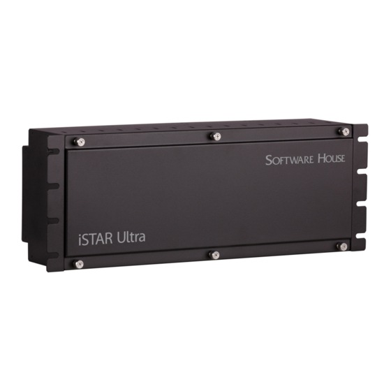
iSTAR Ultra
Tyco iSTAR Ultra Manuals
Manuals and User Guides for Tyco iSTAR Ultra. We have
1
Tyco iSTAR Ultra manual available for free PDF download: Installation And Configuration Manual
Tyco iSTAR Ultra Installation And Configuration Manual (138 pages)
door controller
Brand:
Tyco
| Category:
Control Unit
| Size: 4 MB
Table of Contents
Table of Contents
3
How to Use this Manual
10
Preface
10
Conventions
11
Finding more Information
12
Software House Customer Support Center
13
Chapter 1 Overview and Introduction
16
Overview
16
General Control Module
16
Access Control Module
16
Types of Mounting
18
Wall Mount Enclosure
18
Rack Mount Enclosures
19
Istar Ultra Photograph
20
Main Features
21
Processor
21
Storage
21
Power
21
RM / Wiegand Signaling Readers (Per ACM)
21
Aperio Hubs and Readers (Per GCM RS-485 Comm Port)
22
I/O (Per ACM)
22
I/O (Per GCM)
23
Communications
23
Fai
23
Onboard Controls
23
Housing
24
Product Comparison
25
Chapter 2 Site Requirements
30
Pre-Installation Planning and Requirements
30
Equipment Check
30
Types of Mounting
30
Requirements
30
Site Requirements
30
Istar Ultra Wall Mount Dimensions
31
Wall Mount Hardware
31
Environmental Requirements
32
Installation
33
Wall Mount Installation
33
Requirements
33
Rack Mount Installation
35
Rack Mount Considerations
35
IP-ACM Installation
36
Plastic Enclosure
36
Metal Enclosure
37
Grounding Requirements
38
Power
39
Electrical
39
Additional Power Requirements
41
Battery
41
Wiring Requirements
42
Heat Dissipation
43
Grounding Requirements
44
Reader Power Requirements
45
Software House Readers
45
Third Party Readers
45
Chapter 3 Istar Ultra Network Topology
48
LAN and WAN Configurations
48
Gateways and Firewalls
48
Istar Ultra Network Topology
48
Local Address Management
49
IP Management Tools
50
Fully Qualified Domain Names
50
Cluster Configuration
51
Master and Member Configuration
51
Master Configurations
53
Single Master Configurations
53
Communication Paths
54
Primary Communications Path
54
Secondary Communications Path
55
Maintaining Cluster Communication
56
Single Master Configurations
56
Adding Controllers to the Cluster
57
Configuring Communication Paths
58
Planning Primary Communications
58
Primary Communication Guidelines
58
Planning Secondary Communications
58
Chapter 4 Istar Ultra Power, Batteries, and Backup
60
Power Requirements
60
Power
60
Electrical
60
Maximum Power
61
Additional Power Requirements
62
Heat Dissipation
63
Other Interactions with the Power System
65
AC / Main Fail Input
65
Low Battery Input
65
Chapter 5 General Control Module (GCM)
68
General Control Module
68
Network Connections
69
J3 Battery Backup
69
Switches
69
SW7- Soft Reset (Reboot)
69
SW2 - Hard Processor Reset
70
SW3 Rotary Switch
70
S1-1 (Encryption)
71
S1-2- Cpni
71
RS - 485 Terminators - SW5 and SW6
71
LCD Contrast Potentiometer - RV1
71
AC Fail - Low Battery - J2
71
AC Fail Input
72
Low Battery Input
72
Tamper - J1
72
GCM Power - J4
73
And 2 (J12 and J13)
73
USB Type a - J8 and J9
73
USB Micro A-B - J7
73
Diagnostic Port (P4)
73
COMM Board Connector - J15
73
J14 SD Card
74
Visual Indicators
74
Power - DS1 and DS2
74
Lcd
74
Leds
75
Chapter 6 Access Control Module (ACM)
78
Access Control Module
78
Switches and Jumpers
81
SW10 - ACM MCU Reset
81
J1 USB Type B 2.0 Port
81
SW32 ACM Address Switch
81
RS - 485 Terminators
82
Wet/ Dry Jumpers
82
Output Relay Wet or Dry Jumpers
82
Jumper Settings
82
Activate on FAI
83
FAI on this ACM - SW31
83
Enable FAI Latch - SW30
83
Ports and Connectors
83
J1 USB Connection to GCM
83
Tamper - J22
83
Reader Power - J4
83
LOCK 1 Power - J2
84
LOCK 2 Power - J3
84
FAI and Key - J84
84
Wiegand Connections
85
Wiegand Port Rating
86
AUX Outputs
87
Inputs
87
Supervision Wiring
87
Relay Outputs
88
Dry Relay Wiring
89
Wet Relay Wiring
89
Wet Wiring for a Magnetic Lock
90
Inputs
93
NO/NC Dual EOL 1K
95
NO/NC Dual EOL 5K, 10K
96
Double EOL 1K, 5K, 10K
97
Single EOL 5K, 10K
97
Non-Supervised
98
FAI Connections
99
FAI Scenarios
99
FAI Modes
99
FAI Without Latch
99
FAI with Latch Followed by Key Unlatch
100
F and K Input Supervision
101
State of F, K, and Relay Drive
102
Other Ultra Data from Status Tab
103
Voltage Requirements and Distance
103
Readers and Accessory Boards
106
Chapter 7 IP-ACM Ethernet Door Module
108
Overview
108
Switches and Jumpers
108
IP-ACM Reset - SW3
108
DIP Switch - SW1
108
Rotary Switch - SW2
109
Gige - Poe - J1
109
Ports and Connectors
109
Local Power - P1
109
Tamper - P15
109
Lock Voltage - P2
109
Output 1 - P7
109
Output 2 - P9
109
Wiegand Connections
110
Inputs
110
Power and Wiring
111
Initial Configuration
112
Normal Operation Mode
112
Standalone Configuration Mode
112
Readers and Accessory Boards
113
Chapter 8 Istar Configuration
116
Overview
116
Istar Ultra Limitations
116
Icu
116
Troubleshooting Tools
117
C•Cure
117
Backups
117
LAN Configurations
117
WAN Configurations
118
Chapter 9 Web
120
Displaying Diagnostic Information
120
Web Page Diagnostics
120
Istar Ultra Controller Status Page
121
Cluster Information Page
123
IP-ACM Page
123
Database Page
126
Network Status Page
127
Reader & I/O Diagnostics Page
128
SID Diagnostics Levels Page
129
Chapter 10 Maintenance
131
Setting the LCD Message Display
132
Displaying Status Messages
134
Setting LCD Status Message Display
134
Diagnostic Tests
135
Hardware Test
135
Card Reader Diagnostics
136
Output Diagnostics
136
Output Change Display (Slow Mode)
136
Input Change Display Mode
136
Ethernet Port Test
137
GCM Battery Replacement
138
Advertisement
Advertisement
Related Products
Tyco iSTAR eX
Tyco Illustra Pro series
Tyco IR6003/7
Tyco INTEVO Compact LTE
Tyco INTEVO Compact
Tyco INTEVO-CMP-2TB
Tyco INTEVO-ADV-4TB
Tyco INTEVO Advanced
Tyco Illustra Pro IPS03CFOCWST
Tyco Illustra Pro
Tyco Categories
Irrigation System
Control Unit
Security System
Security Sensors
Smoke Alarm
More Tyco Manuals
Login
Sign In
OR
Sign in with Facebook
Sign in with Google
Upload manual
Upload from disk
Upload from URL