Sign In
Upload
Manuals
Brands
Teledyne Manuals
Measuring Instruments
T400
User Manuals: Teledyne T400 UV Absorption Analyzer
Manuals and User Guides for Teledyne T400 UV Absorption Analyzer. We have
1
Teledyne T400 UV Absorption Analyzer manual available for free PDF download: User Manual
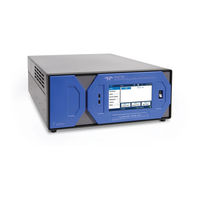
Teledyne T400 User Manual (177 pages)
Photometric Ozone Analyzer with NumaView software
Brand:
Teledyne
| Category:
Measuring Instruments
| Size: 12 MB
Table of Contents
Table of Contents
10
Introduction, Specifications, Approvals, & Compliance
18
Specifications
19
Table 1-1. T400 Basic Unit Specifications
19
EPA Designation
20
Safety
20
Emc
20
Other Type Certifications
20
Table 1-2. IZS Generator Specifications with Reference Feedback Option
20
Table 1-3. IZS Generator Specifications Without Reference Feedback Option
20
Getting Started
21
Unpacking
21
Ventilation Clearance
22
Table 2-1. Ventilation Clearance
22
Instrument Layout
23
Front Panel
23
Figure 2-1. Front Panel Layout
23
Rear Panel
24
Figure 2-2. Rear Panel Layout
24
Table 2-2. Rear Panel Description
25
Internal Chassis
26
Figure 2-3. T400 Internal Layout - Top View with IZS Option
26
Connections and Startup
27
Electrical Connections
27
Connecting Power
27
Connecting Analog Outputs
28
Current Loop Analog Outputs (Option 41) Setup
28
Figure 2-4. Analog Output Connector
28
Table 2-3. Analog Output Pin-Outs
28
Figure 2-5. Current Loop Option Installed on Motherboard
29
Connecting the Status Outputs (Digital Outputs)
31
Figure 2-6. Status Output Connector for Digital Outputs
31
Table 2-4. Status Output Pin Assignments
31
Connecting the Control Inputs (Digital Inputs)
32
Figure 2-7. Control Input Connector
32
Table 2-5. Control Input Signals
32
Connecting the Concentration Alarm Relay (Option 61)
33
Connecting the Communication Interfaces
33
Figure 2-8. Concentration Alarm Relay
33
Figure 2-9. Rear Panel Connector Pin-Outs for RS-232 Mode
34
Figure 2-10. Default Pin Assignments for CPU COM Port Connector (RS-232)
35
Figure 2-11. Jumper and Cables for Multidrop Mode
37
Figure 2-12. RS-232-Multidrop PCA Host/Analyzer Interconnect Diagram
38
Pneumatic Connections
39
Important Information about Calibration Gases
40
Pneumatic Connections: Basic Configuration
41
Figure 2-13. Gas Line Connections for the T400 Analyzer - Basic Configuration
41
Pneumatic Connections: Zero/Span (Z/S) Option
43
Figure 2-14. Gas Line Connections for the T400 Analyzer with Zero/Span Valve Option (OPT 50A)
43
Pneumatic Connections: Internal Zero/Span (IZS) Option
45
Figure 2-15. Gas Line Connections for the T400 Analyzer with IZS Option (OPT 50G)
45
Pneumatic Connections: Ambient Air Monitoring in same Room
46
Figure 2-16. Gas Line Connections When the T400 Analyzer Is Located in the Room Being Monitored
46
Pneumatic Connections: Ambient Air Monitoring in Remote Locations
47
Figure 2-17. Gas Line Connections When the T400 Analyzer Is Monitoring a Remote Location
47
Pneumatic Flow Diagrams
48
Pneumatic Flow: Basic Configuration
48
Figure 2-18. T400 Pneumatic Diagram - Basic Unit
48
Pneumatic Flow: Zero/Span (ZS) Valve Option
49
Figure 2-19. T400 Pneumatic Diagram with Zero/Span (ZS) Option (OPT50A)
49
Table 2-6. Zero/Span Valve Operating States for Option 50A
49
Pneumatic Flow: Internal Zero/Span (IZS) Valve Option
50
Figure 2-20. T400 Pneumatic Diagram with Internal Zero/Span (IZS) Option (OPT50G)
50
Table 2-7. Internal Zero/Span Valve Operating States for Option 50G
50
Startup, Functional Checks, and Initial Calibration
51
Startup
51
Figure 2-21. Status Screens at Startup
51
Alerts: Warnings and Other Messages
52
Figure 2-22. Home Page Example
52
Figure 2-23. Viewing Active Alerts Page
52
Functional Checks
53
Initial Calibration
53
Figure 2-24. Sample Dashboard Page
53
Menu Overview
54
Table 2-6. Menu Overview
54
Home Page
55
Dashboard
57
Alerts
57
Calibration
59
Utilities
60
Setup
60
Table 2-7. Utilities Submenu Descriptions
60
Setup Menu: Features/Functions Configuration
61
Setup>Data Logging (Data Acquisition System, DAS)
61
Configuring Trigger Types: Periodic
64
Configuring Trigger Types: Conditional
65
Downloading das (Data Acquisition System) Data
65
Figure 2-36. das Download Page
65
Setup>Events
66
Editing or Deleting Events
68
Using Events as Triggers for Data Logging
69
Setup>Dashboard
69
Setup>Autocal (with Valve Option)
70
Setup>Vars
70
Table 2-8. List of Variables with Descriptions
70
Setup>Homescreen
71
Figure 2-42. Homescreen Configuration
71
Setup>Digital Outputs
72
Figure 2-43. Digital Outputs Setup
72
Setup>Analog Outputs
73
Figure 2-44. Analog Output Configuration Example
73
Figure 2-45. Analog Outputs Group Calibration Screen
74
Figure 2-46. Analog Outputs Manual Calibration Screen (AOUT2 Example)
74
Table 2-9. Analog Output Voltage/Current Range
74
Manual Calibration of Voltage Range Analog Outputs
75
Figure 2-47. Setup for Checking / Calibrating DCV Analog Output Signal Levels
75
Table 2-10. Voltage Tolerances
75
Manual Adjustment of Current Range Analog Outputs
76
Figure 2-48. Setup for Checking / Calibration Current Output Signal Levels
76
Setup>Instrument
77
Figure 2-49. Alternative Setup Using 250Ω Resistor for Checking Current Output Signal Levels
77
Table 2-11. Current Loop Output Check
77
Table 2-12. Setup>Instrument Menu
77
Setup>Comm (Communications)
78
Com1/Com2
78
Table 2-13. COM1/COM2 Configuration
78
TCP Port1
79
TCP Port2
79
TCP Port3
79
Network Settings
80
Figure 2-50. Communications Configuration, Network Settings
80
Table 2-14. Lan/Ethernet Configuration Properties
80
Transferring Configuration to Other Instruments
81
Figure 2-51. Configuration Transfer
81
Communications and Remote Operation
82
Data Terminal/Communication Equipment (DTE DCE)
82
Modes, Baud Rate and Serial Communication
82
Serial Communication: RS-232
83
Serial Communication: RS-485 (Option)
83
Ethernet
83
Table 3-1. Ethernet Status Indicators
83
Communications Protocols
84
Modbus
84
MODBUS Com Port Configuration
84
Figure 3-1. MODBUS Via Ethernet
84
Figure 3-2. MODBUS Via Serial Communication (Example)
85
Hessen
86
Hessen Com Port Configuration
86
Figure 3-3. Serial Communication, Setting Hessen Protocol
86
Hessen Settings Configuration
87
Table 3-2. Teledyne Api's Hessen Protocol Response Modes
87
Table 3-3. Default Hessen Status Flag Assignments
88
Calibration
89
Important Precalibration Information
89
Calibration Requirements
89
Zero Air
89
Calibration (Span) Gas
90
Interferents
90
Dilution Ratio Option Software Set up
90
Data Recording Devices
91
Calibration Procedures
91
Calibration and Check Procedures for Basic Configuration
91
Zero Calibration Check and Actual Calibration
92
Span Calibration Check and Actual Calibration
92
Figure 4-1. Multi-Point Calibration Page
92
Calibration and Check Procedures with Valve Options Installed
93
Figure 4-2. Zero and Span Calibration Screens
93
Use of Zero/Span Valve with Remote Contact Closure
94
Automatic Zero/Span Cal/Check (Auto Cal)
94
Figure 4-3. Auto Cal Page
95
Table 4-1. AUTO CAL States
95
Table 4-2. Auto Cal Setup Combinations
96
Table 4-3. Auto Cal Programming Sequence Execution
96
Calibration Quality
97
Calibration of the Electronic Subsystems
97
Pressure Calibration
97
Flow Calibration
97
O 3 Gen Calibration
98
EPA Protocol Calibration
98
Maintenance and Service
99
Maintenance Schedule
99
Table 5-1. T400 Maintenance Schedule
100
Predicting Diagnostics
102
Table 5-2. Predictive Uses for Dashboard Functions
102
Operational Health Checks
103
Software/Firmware Updates
103
Remote Updates
103
Figure 5-1. Report Generation Page
103
Manual Reload/Update Procedures
104
Figure 5-2. Remote Update Page
104
Figure 5-3. Manual Update Page (and Other Utilities)
104
Instrument Display Calibration (for Earlier Instruments)
105
Figure 5-4. Touchscreen Calibration Page
105
Time Zone Changes
106
Figure 5-5. Time Zone Change Requirements
106
Maintenance Procedures
107
Replacing the Sample Particulate Filter
107
Figure 5-6. Replacing the Particulate Filter
107
Rebuilding the Sample Pump
108
Replacing the IZS Option Zero Air Scrubber
108
Figure 5-7. Replacing the IZS Zero Air Scrubber
108
IZS Desiccant Option
109
Performing Leak Checks
109
Vacuum Leak Check and Pump Check
109
Pressure Leak Check
110
Performing a Sample Flow Check
111
Maintaining the Photometer Absorption Tube
111
Adjusting the Optical Bench UV Lamp
112
Figure 5-8. Optical Bench - Lamp Adjustment/ Installation
112
Replacing the Optical Bench UV Lamp
113
Adjusting or Replacing the Izs Ozone Generator Option Suv Lamp
114
Figure 5-9. O 3 Generator UV Lamp
114
Figure 5-10. Location of O
115
Service and Troubleshooting
116
Fault Diagnosis with Alerts
117
Table 5-3. Alerts - Indicated Failures
117
Fault Diagnosis with Dashboard Functions
118
Table 5-4. Dashboard Functions - Indicated Failures
119
The Diagnostic Signal I/O Function
120
Status Leds
120
CPU Status Indicator
120
Figure 5-11. CPU Status Indicator
120
I 2 C Bus Watchdog Status LED
121
O 3 Option Status LED
121
Figure 5-12. Relay PCA Status Leds Used for Troubleshooting
121
Table 5-5. Relay PCA Watchdog LED Failure Indication
121
Table 5-6. Relay Board Watchdog and Status LED Failure Indications
122
Flow Problems
123
Flow Is Zero
123
Low Flow
124
High Flow
124
Actual Flow Does Not Match Displayed Flow
124
Sample Pump
124
Calibration Problems
124
Miscalibrated
124
Non-Repeatable Zero and Span
125
Inability to Span - no SPAN Button (CALS)
125
Inability to Zero - no ZERO Button (CALZ)
125
Other Performance Problems
125
Temperature Problems
125
Box Temperature
126
Sample Temperature
126
UV Lamp Temperature
126
IZS Ozone Generator Temperature (Optional)
126
Subsystem Checkout
127
AC Mains Configuration
127
DC Power Supply
128
I 2 C Bus
128
Table 5-7. DC Power Test Point and Wiring Color Codes
128
Table 5-8. DC Power Supply Acceptable Levels
128
Touchscreen Interface
129
LCD Display Module
129
Relay Board
129
Table 5-9. Relay Board Control Devices
129
Pressure/Flow Sensor Assembly
130
Motherboard
131
A/D Functions
131
Status Outputs
131
Figure 5-13. Typical Set up of Status Output Test
131
Control Inputs - Remote Zero, Span
132
Cpu
132
Communications
132
General RS-232 Troubleshooting
132
Troubleshooting the Photometer
133
Checking the Measure/Reference Valve
133
Checking the Photometer UV Lamp Power Supply
133
Troubleshooting the IZS Option's O Generator
134
Service Procedures
134
Repairing Sample Flow Control Assembly
134
Replacing the Standard Reference O3 Scrubber
135
Replacing the Izs Oscrubber
135
Figure 5-14. Critical Flow Restrictor Assembly/Disassembly
135
Replacing the Metal Wool Scrubber Option
136
Replacing the UV Lamp Driver Board
136
Figure 5-16: UV Lamp Driver Board Replacement
137
Disk-On-Module Replacement
138
Frequently Asked Questions
139
Technical Assistance
140
Theory of Operation
141
Measurement Method
141
Calculating O Concentration
142
The Photometer UV Absorption Path
143
Figure 6-1. O 3 Absorption Path
143
The Reference / Measurement Cycle
144
Figure 6-2. Reference / Measurement Gas Cycle
144
Interferent Rejection
145
Aromatic Hydrocarbons
145
Mercury Vapor
145
Pneumatic Operation
145
Sample Gas Air Flow
146
Flow Rate Control
146
Figure 6-3. Internal Pneumatic Flow - Basic Configuration
146
Particulate Filter
147
Figure 6-4. Flow Control Assembly & Critical Flow Orifice
147
Pneumatic Sensors
148
Sample Pressure Sensor
148
Sample Flow Sensor
148
Electronic Operation
148
Figure 6-5. Electronic Block Diagram
149
Cpu
150
Disk-On-Module (DOM)
150
Flash Chip
150
Figure 6-6. CPU Board
150
Motherboard
151
A to D Conversion
151
Sensor Inputs
151
Thermistor Interface
151
Analog Outputs
152
External Digital I/O
152
Power up Circuit
152
I 6.3.3 Relay Board
153
C Data Bus
153
Figure 6-7. Relay Board Layout
153
Status Leds
154
Figure 6-8: Relay Board with Safety Shield in Place
154
Figure 6-9: Relay Board with AC Relay Retainer in Place
154
I 2 C Watch Dog Circuitry
155
Heater Control
155
Figure 6-10. Relay Board Status LED Locations
155
Table 6-1. Relay Board Status Leds
155
Valve Control
156
Figure 6-11: Heater Control Loop Block Diagram
156
Thermocouple Inputs and Configuration Jumper (JP5)
157
Table 6-2. Thermocouple Configuration Jumper (JP5) Pin-Outs
157
Power Supply/ Circuit Breaker
158
Figure 6-12. Power Distribution Block Diagram
158
AC Power Configuration
159
Figure 6-13. Location of AC Power Configuration Jumpers
159
AC Configuration - Internal Pump (JP7)
160
AC Configuration - Heaters for Option Packages (JP6)
160
Figure 6-14. Pump AC Power Jumpers (JP7)
160
Table 6-3. AC Power Configuration for Internal Pumps (JP7)
160
Table 6-4. Power Configuration for Optional Metal Wool Scrubber Heater (JP6)
160
Photometer Layout and Operation
161
Figure 6-15. Typical Jumper Set (JP2) Set up of Optional Metal Wool Scrubber Heater
161
Front Panel Touchscreen/Display Interface
162
Figure 6-16. O 3 Photometer Layout - Top Cover Removed
162
LVDS Transmitter Board
163
Front Panel Touchscreen/Display Interface PCA
163
Software Operation
163
Figure 6-17. Front Panel and Display Interface Block Diagram
163
Adaptive Filter
164
Temperature/Pressure Compensation (TPC)
164
Figure 6-18. Basic Software Operation
164
Calibration - Slope and Offset
165
Advertisement
Advertisement
Related Products
Teledyne T200
Teledyne T201
Teledyne T300
Teledyne T300M
Teledyne T320U
Teledyne T360M
Teledyne T3MIL50
Teledyne T3CP50-50
Teledyne T3VNA
Teledyne T3VNA3200
Teledyne Categories
Measuring Instruments
Analytical Instruments
Test Equipment
Digital Camera
Laboratory Equipment
More Teledyne Manuals
Login
Sign In
OR
Sign in with Facebook
Sign in with Google
Upload manual
Upload from disk
Upload from URL