Sign In
Upload
Manuals
Brands
Suzuki Manuals
Automobile
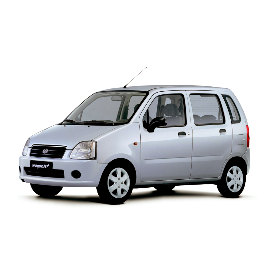
Wagon R Plus RB310
User Manuals: Suzuki Wagon R Plus RB310 Kei Car
Manuals and User Guides for Suzuki Wagon R Plus RB310 Kei Car. We have
1
Suzuki Wagon R Plus RB310 Kei Car manual available for free PDF download: Service Manual
Suzuki Wagon R Plus RB310 Service Manual (847 pages)
Brand:
Suzuki
| Category:
Automobile
| Size: 20.35 MB
Table of Contents
Table of Contents
4
General Information
6
How to Use this Manual
7
Precautions
8
Diagnosis
9
Servicing and Handling
10
General Precautions
12
Brakes
12
Precaution for CAN Communication System
15
Precaution for Wheel (with Tire) Removal
15
Precautions for Catalytic Converter
15
Precaution for Installing Mobile Communication Equipment
15
Precaution in Servicing Full-Time 4WD Vehicle
16
Precautions for Electrical Circuit Service
17
Electrical Circuit Inspection Procedure
20
Open Circuit Check
20
Continuity Check
21
Voltage Check
21
Short Circuit Check (Wire Harness to Ground)
22
Intermittent and Poor Connection
22
Identification Information
24
Vehicle Identification Number
24
Engine Identification Number
24
Transmission Identification Number
24
Warning, Caution and Information Labels
25
Vehicle Lifting Points
26
When Using Frame Contact Hoist
26
When Using Floor Jack
27
Abbreviations and Symbols May be Used in this Manual
28
Symbols
30
Wire Color Symbols
30
Fastener Information
31
Metric Fasteners Information
31
JIS-TO-ISO Main Fasteners Comparison Table
31
Fastener Strength Identification
32
Standard Tightening Torque
32
Tightening Torque Chart
33
Maintenance and Lubrication
34
Maintenance Schedule under Normal Driving Conditions
36
Maintenance Recommended under Severe Driving Conditions
38
Maintenance Service
39
Drive Belt Inspection (M13 Engine)
39
Water Pump and Generator Drive Belt Inspection
39
Drive Belt Replacement (M13 Engine)
39
Drive Belt Inspection (G10 Engine)
40
Drive Belt Replacement (G10 Engine)
40
A/C Compressor Drive Belt Replacement
40
Water Pump Belt Replacement
40
Camshaft Timing Belt Replacement
41
Valve Lash (Clearance) Inspection
41
Engine Oil and Oil Filter Replacement
42
Engine Oil Specification
43
Engine Coolant Replacement
44
Exhaust System Inspection
44
Spark Plugs Replacement
44
Distributor Cap and Rotor Inspection
45
Air Cleaner Filter Inspection
45
Air Cleaner Filter Replacement
45
Fuel Lines and Connections Inspection
45
Fuel Tank Inspection
46
PCV Valve Inspection
46
Fuel Evaporative Emission Control System Inspection
46
Brake Discs and Pads (Front) Inspection
46
Brake Drums and Shoes (Rear) Inspection
47
Brake Hoses and Pipes Inspection
47
Brake Fluid Replacement
47
Brake Lever and Cable Inspection
47
Clutch Inspection
48
Tires Inspection
48
Wheel Discs Inspection
49
Wheel Bearing Inspection
49
Suspension System Inspection
49
Steering System Inspection
49
Drive Shaft (Axle) Boots Inspection
50
Propeller Shafts (4WD) Inspection
50
Manual Transmission Oil Inspection
51
Manual Transmission Oil Replacement
51
Automatic Transmission Fluid Level Inspection
51
Automatic Transmission Fluid Replacement
52
Automatic Transmission Fluid Cooler Hose Inspection
52
Transfer Oil (4WD) and Rear Differential Oil (4WD) Inspection
52
Transfer Oil (4WD) and Rear Differential Oil (4WD) Replacement
53
All Latches, Hinges and Locks Inspection
53
Doors
53
Engine Hood
53
Final Inspection
54
Battery Electrolyte Level Check
54
Accelerator Pedal Operation
54
Exhaust System Check
54
Foot Brake
55
Parking Brake
55
Steering
55
Meters and Gauge
55
Recommended Fluids and Lubricants
56
Air Conditioning
58
Wiring Circuit (M13 Engine Model)
59
A/C System Inspection of ECM and Its Circuits (M13 Engine Model)
60
Terminal Arrangement of ECM Coupler (Viewed from Harness Side)
61
ECM Voltage Values Table for Relation of A/C Control (M13 Engine Model)
61
Compressor Drive Belt (M13 Engine Model)
62
On-Vehicle Service
63
Dual Pressure Switch
63
A/C Compressor Relay
63
Compressor Removal
64
Front Wheel Alignment
66
General Description
67
Front Wheel Alignment Specifications
67
Manual Rack and Pinion
68
Tie Rod End
69
Manual Rack and Pinion Assembly
70
Tightening Torque Specifications
71
Electrical Power Steering (Eps) System
72
Wiring Diagram
73
“EPS” Warning Lamp Circuit Check Flow Table for M13 Engine Model
74
Table-B “EPS” Warning Lamp Remains on
75
Front Suspension
76
Wheel Disc, Bolt & Bearing Check
78
Stabilizer Bar And/Or Bushings
79
Strut Assembly
80
Steering Knuckle / Bearing
81
Tightening Torque
81
Suspension Control Arm / Bushing
87
Required Service Material
90
Special Tool
90
Rear Suspension
92
Wheel Disc, Bolt and Bearing Check
95
Lateral Rod
98
Coil Spring
99
Bump Stopper
100
Trailing Arm
100
Rear Axle (for 2WD Model)
102
Wheel Bearing (for 2WD Model)
104
Rear Axle Shaft and Wheel Bearing
106
Rear Axle Housing (for 4WD Model)
110
Wheels and Tires
118
Maintenance and Minor Adjustments
119
Wheel Maintenance
119
Tire Rotation
119
Service Operations
120
Wheel Bolts
120
Wheel Removal
120
Wheel Installation
120
Front Drive Shaft
122
Front Drive Shaft Assembly Construction
123
Front Drive Shaft Assembly Removal and Installation
124
Front Drive Shaft Components
127
Front Drive Shaft Disassembly and Assembly
128
For DOJ Type
128
For Tripod Joint Type
129
Assembly
131
Grease Color
135
Tightening Torque Specification
139
Propeller Shafts
142
On-Vehicle Inspection
143
Brakes
148
Check and Adjustment
150
Bleeding Brakes
150
Brake Shoe Check
152
Brakes Pipe/Hose/Master Cylinder
154
Rear Brake Hose/Pipe
155
Front Brake
158
Front Disc Brake Pad
159
Front Disc Brake Caliper
160
Front Brake Disc
161
Parking and Rear Brake
164
Brake Drum
168
Brake Drum Removal and Installation
170
Brake Back Plate
174
Engine General Information and Diagnosis
176
Statement on Cleanliness and Care
178
General Information
178
Precaution on Engine Service
179
Precaution on Fuel System Service
179
Fuel Pressure Relief Procedure
180
Fuel Leakage Check Procedure
181
Engine Diagnosis General Description
182
On-Board Diagnostic System Description
182
Warm-Up Cycle
182
Driving Cycle
183
2 Driving Cycle Detection Logic
183
Pending DTC
183
Freeze Frame Data
183
Freeze Frame Data Clearance
184
Data Link Connector (DLC)
184
Precaution in Diagnosing Trouble for Engine
185
Engine and Emission Control System Check
186
Customer Complaint Analysis
187
Diagnostic Trouble Code (Dtc)/Freeze Frame Data Check, Record and Clearance
187
Trouble Symptom Confirmation
187
Engine Basic Inspection and Engine Symptom Diagnosis
187
Customer Problem Inspection Form (Example)
188
Malfunction Indicator Lamp (MIL) Check
189
Diagnostic Trouble Code (DTC) Check
189
Diagnostic Trouble Code (DTC) Clearance
189
Fail-Safe Table
194
Visual Inspection
195
Engine Basic Inspection
196
Engine Symptom Diagnosis
198
Scan Tool Data
206
Scan Tool Data Definitions
208
Inspection of ECM and Its Circuits
211
Reference Waveform
219
Resistance Check
227
Component Location
228
Table A-1 Malfunction Indicator Lamp Circuit Check – Lamp Does Not Come “ON” with Ignition Switch on (but Engine Stops)
229
Table A-2 Malfunction Indicator Lamp Circuit Check-Lamp Remains “ON” after Engine Starts
231
Table A-3 ECM Power and Ground Circuit Check-MIL Doesn’t Light with Ignition Switch on and Engine Doesn’t Start Though It Is Cranked up
233
DTC P0010 Camshaft Position Actuator Circuit
236
DTC P0011 Camshaft Position – Timing Over-Advanced or System Performance
239
DTC P0012 Camshaft Position – Timing Over-Retarded
239
DTC P0102 Mass Air Flow Circuit Low Input
241
DTC P0103 Mass Air Flow Circuit High Input
244
DTC P0112 Intake Air Temperature Sensor Circuit Low
246
DTC P0113 Intake Air Temperature Sensor Circuit High
248
DTC P0117 Engine Coolant Temperature Circuit Low
251
DTC Detecting Condition and Trouble Area
251
DTC Confirmation Procedure
251
DTC P0118 Engine Coolant Temperature Circuit High
253
DTC P0121 Throttle Position Sensor Circuit Range/Performance
256
DTC P0122 Throttle Position Sensor Circuit Low
260
DTC P0123 Throttle Position Circuit High Input
263
DTC P0131 O2 Sensor (HO2S) Circuit Low Voltage (Sensor-1)
266
DTC P0132 O2 Sensor (HO2S) Circuit High Voltage (Sensor-1)
266
DTC P0133 O2 Sensor (HO2S) Circuit Slow Response (Sensor-1)
269
DTC P0134 O2 Sensor (HO2S) no Activity Detected (Sensor-1)
270
DTC P0031 HO2S Heater Control Circuit Low (Sensor-1)
273
DTC P0032 HO2S Heater Control Circuit High (Sensor-1)
273
DTC P0136 O2 Sensor (HO2S) Circuit (Sensor-2)
276
DTC P0037 HO2S Heater Control Circuit Low (Sensor-2)
279
DTC P0038 HO2S Heater Control Circuit High (Sensor-2)
279
DTC P0300 Random Misfire Detected
283
DTC P0301 Cylinder 1 Misfire Detected
283
DTC P0302 Cylinder 2 Misfire Detected
283
DTC P0303 Cylinder 3 Misfire Detected
283
DTC P0327 Knock Sensor Circuit Low
285
DTC P0328 Knock Sensor Circuit High
285
DTC P0335 Crankshaft Position (CKP) Sensor Circuit
287
DTC P0340 Camshaft Position Sensor Circuit
291
DTC P0401 Exhaust Gas Recirculation Flow Insufficient Detected
295
DTC P0402 Exhaust Gas Recirculation Flow Excessive Detected
295
DTC Detecting Condition and Trouble Area (DTC P0401/P0402)
296
DTC P0420 Catalyst System Efficiency below Threshold
298
DTC P0443 Evaporative Emission System Purge Control Valve Circuit
300
DTC P0480 Fan 1 (Radiator Cooling Fan) Control Circuit
302
DTC P0500 Vehicle Speed Sensor (VSS) Malfunction
305
DTC P0505 Idle Air Control System
309
DTC P1500 Starter Signal Circuit Malfunction
311
DTC P0107 Manifold Absolute Pressure Low Input
313
DTC P0108 Manifold Absolute Pressure High Input
316
DTC P1510 ECM Back-Up Power Supply Malfunction
319
DTC P1601 Can Communication Error
321
DTC P2227 Barometric Pressure Circuit Range/Performance
324
DTC P2228 Barometric Pressure Circuit Low
324
DTC P2229 Barometric Pressure Circuit High
324
Table B-1 Fuel Injector Circuit Check
325
Table B-2 Fuel Pump and Its Circuit Check
327
Idle Air Control System Check
331
A/C Signal Circuits Check (Vehicle with A/C)
333
Electric Load Signal Circuit Check
336
Radiator Fan Control System Check
337
Engine Mechanical (M13 Engine)
340
Engine Construction Description
342
Engine Lubrication Description
343
Variable Valve Timing (VVT) System Description
344
Oil Control Valve
345
Cam Timing Sprocket
345
Timing Advancing
345
Timing Holding
345
Timing Retarding
346
Targeted Timing Varying Operation
346
Diagnosis Table
347
Compression Check
347
Engine Vacuum Check
348
Oil Pressure Check
350
Shim Replacement
352
Valve Clearance Specification
352
Air Cleaner Element Removal and Installation
355
Air Cleaner Element Inspection and Cleaning
356
Knock Sensor Removal and Installation
356
Cylinder Head Cover Removal and Installation
356
Throttle Body and Intake Manifold Components
359
Throttle Body Removal and Installation
360
Intake Manifold Removal and Installation
361
Exhaust Manifold Components
362
Exhaust Manifold Removal and Installation
363
Oil Pan and Oil Pump Strainer Components
365
Oil Pan and Oil Pump Strainer Removal and Installation
365
Engine Mountings Components
368
Unit Repair Overhaul
369
Engine Assembly Removal and Installation
369
Timing Chain Cover Components
373
Timing Chain Cover Removal and Installation
374
Oil Gallery Pipe
378
Oil Pump Components
378
Oil Pump Removal and Installation
379
Oil Pump Disassembly and Assembly
379
Oil Pump Inspection
381
Oil Seal
381
Oil Pump Assembly
381
Radial Clearance
382
Side Clearance
382
Relief Valve Spring Free Length and Load
382
Timing Chain and Chain Tensioner Components
383
Timing Chain and Chain Tensioner Removal and Installation
383
Camshaft, Tappet and Shim Components
389
Camshaft, Tappet and Shim Removal and Installation
389
Camshaft, Tappet and Shim Inspection
392
Intake Cam Timing Sprocket Assembly
392
Cam Wear
393
Camshaft Runout
393
Camshaft Journal Wear
393
Camshaft Journal Clearance
394
Camshaft Journal Diameter
394
Wear of Tappet and Shim
394
Valves and Cylinder Head Components
395
Valves and Cylinder Head Removal and Installation
396
Valves and Cylinder Head Disassembly and Assembly
399
Pistons, Piston Rings, Connecting Rods and Cylinders Components
406
Spring Squareness
406
Pistons, Piston Rings, Connecting Rods and Cylinders Removal and Installation
407
Pistons, Piston Rings, Connecting Rods and Cylinders Disassembly and Assembly
408
Piston Clearance
411
Ring Groove Clearance
411
Piston Pin
411
Piston Pin Clearance
412
Piston Rings
412
Piston Ring End Gap
412
Connecting Rod
413
Big-End Side Clearance
413
Connecting Rod Alignment
413
Connecting Rod Bolt Deformation
413
Crank Pin and Connecting Rod Bearings
414
Crank Pin Diameter
414
Connecting Rod Bearing General Information
414
Connecting Rod Bearing Visual Inspection
414
Selection of Connecting Rod Bearings
415
Crankshaft Pin Outer Diameter
416
Connecting Rod Big End Inside Diameter
416
Standard Size of Connecting Rod Bearing Thickness
417
Specification of New Standard Connecting Rod Bearing Size
417
Main Bearings, Crankshaft and Cylinder Block Components
418
Main Bearings, Crankshaft and Cylinder Block Removal and Installation
419
Out-Of-Round and Taper (Uneven Wear) of Journals
424
Main Bearings
424
Crankshaft Thrust Play
424
Main Bearing Clearance
425
Selection of Main Bearings
426
Standard Bearing
426
Crankshaft Journal Diameter
426
Crankshaft Bearing Cap Bore
427
Standard Size of Crankshaft Main Bearing Thickness
427
Specification of New Standard Crankshaft Main Bearing Size
428
Undersize Bearing
428
Undersize of Crankshaft Main Bearing Thickness
428
Specification of New Standard Undersize Crankshaft Main Bearing
429
Rear Oil Seal
429
Flywheel Face Runout
429
Sensor Plate
430
Cylinder Block
430
Distortion of Gasketed Surface
430
Honing or Reboring Cylinders
430
Engine Cooling (M13 Engine)
436
Cooling System Circulation
437
Coolant
438
Anti-Freeze Proportioning Table
438
Coolant Capacity
438
Maintenance
440
Coolant Level Check
440
Engine Cooling System Inspection and Service
441
Cooling System Flush and Refill
441
Water Pump/Generator Drive Belt Tension Inspection and Adjustment
443
Cooling System Components
444
Cooling System Draining
445
Cooling System Refill
445
Cooling Water Pipes or Hoses
445
Thermostat Removal and Installation
446
Thermostat Inspection
446
Radiator Removal and Installation
447
Radiator Inspection
448
Radiator Cleaning
448
Radiator Cooling Fan Relay Inspection
448
Radiator Cooling Fan Removal and Installation
448
Radiator Cooling Fan Inspection
449
Water Pump/Generator Drive Belt Removal and Installation
450
Water Pump Removal and Installation
451
Water Pump Inspection
452
Engine Coolant Temperature Sensor Removal and Installation
452
Engine and Emission Control System
454
Engine and Emission Control System Construction
456
Engine and Emission Control System Flow Diagram
457
Engine and Emission Control System Diagram
458
Air Intake System Description
459
Air Intake System Diagram
459
Fuel Delivery System Description
460
Fuel Delivery System Diagram
460
Fuel Pump
460
Electronic Control System Description
461
Electronic Control System Component Location
462
Engine and Emission Control Input/Output Table
463
ECM Input/Output Circuit Diagram
464
ECM Terminal Arrangement Table
466
Accelerator Cable Adjustment
468
Idle Speed/Idle Air Control (IAC) Duty Inspection
468
Engine Idle Speed and IAC Duty
469
Air Intake System
470
Throttle Body Components
470
Throttle Body On-Vehicle Inspection
470
Throttle Body Cleaning
472
Idle Air Control (IAC) Valve Operation Check
472
Using Suzuki Scan Tool
472
Not Using SUZUKI Scan Tool
472
Idle Air Control (IAC) Valve Check
473
Oil Control Valve Removal and Installation
474
Oil Control Valve Inspection
474
Fuel Delivery System
475
Fuel Pressure Inspection
475
Fuel Pressure Specification
475
Fuel Pump with Pressure Regulator On-Vehicle Inspection
476
Fuel Pump with Pressure Regulator Removal and Installation
477
Fuel Pump with Pressure Regulator Inspection
477
Fuel Injector On-Vehicle Inspection
477
Fuel Injector Removal and Installation
478
Fuel Injector Inspection
479
Injected Fuel Volume
480
Fuel Leakage
480
Electronic Control System
481
Engine Control Module (ECM) Removal and Installation
481
Manifold Absolute Pressure Sensor (MAP Sensor) Inspection
482
Throttle Position Sensor (TP Sensor) On-Vehicle Inspection
483
Throttle Position Sensor (TP Sensor) Removal and Installation
483
Engine Coolant Temperature Sensor (ECT Sensor) Removal and Installation
484
Engine Coolant Temperature Sensor (ECT Sensor) Inspection
485
Heated Oxygen Sensor (HO2S-1 and HO2S-2) Heater On-Vehicle Inspection
485
Heated Oxygen Sensor (HO2S-1 and HO2S-2) Removal and Installation
486
Camshaft Position Sensor (CMP Sensor) and Its Circuit Inspection
486
Camshaft Position Sensor (CMP Sensor) Removal and Installation
487
Crankshaft Position Sensor (CKP Sensor) and Its Circuit Inspection
487
Crankshaft Position Sensor (CKP Sensor) Removal and Installation
488
Fuel Level Sensor Removal and Installation
488
Fuel Level Sensor Inspection
488
Vehicle Speed Sensor (VSS) and Its Circuit Inspection
489
Vehicle Speed Sensor (VSS) Removal and Installation
489
Main Relay, Fuel Pump Relay and Radiator Fan Relay Inspection
490
Fuel Cut Operation Inspection
490
Radiator Fan Control System Inspection
491
System Inspection
491
Mass Air Flow (MAF) and Intake Air Temperature (IAT) Sensor On-Vehicle Inspection
491
Mass Air Flow (MAF) and Intake Air Temperature (IAT) Sensor Removal and Installation
492
Mass Air Flow (MAF) and Intake Air Temperature (IAT) Sensor Inspection
493
Intake Air Temperature Sensor Resistance
493
Emission Control System
494
EGR System Inspection
494
EGR Valve Removal and Installation
494
EGR Valve Inspection
494
Evaporative Emission Control System Inspection
495
EVAP Canister Purge
495
EVAP Canister Purge Valve and Its Circuit
495
Vacuum Passage
496
EVAP Canister Purge Valve Specification
496
Vacuum Hose
497
EVAP Canister Purge Valve
497
EVAP Canister Resistance
497
EVAP Canister
498
PCV System Inspection
498
PCV Hose
498
PCV Valve
498
Ignition System
502
Ignition System Construction
503
Ignition System Components Locator Diagram
503
Ignition System Wiring Circuit Diagram
504
Ignition System Symptom Diagnosis
505
Ignition System Diagnostic Flow Table
506
Ignition Spark Test
508
High-Tension Cords Removal and Installation
508
High-Tension Cords Inspection
509
Spark Plugs Removal and Installation
509
Spark Plugs Inspection
510
Ignition Coil Assembly (Including Ignitor) Removal and Installation
511
Ignition Coil Assembly (Including Ignitor) Inspection
511
Crankshaft Position (CKP) Sensor
512
Ignition Timing Inspection
512
Cranking System
514
Charging System
516
Generator
517
Undercharged Battery
517
No-Load Check
517
Load Check
518
Exhaust System (M13 Engine)
520
Exhaust System Components
522
Exhaust Manifold Inspection
523
Exhaust Pipe Removal and Installation
523
Manual Transaxle (M13 Engine)
524
Manual Transaxle Construction and Servicing
525
Transaxle for 2Wd Model
526
Transaxle for 4Wd Model
527
Manual Transaxle Symptom Diagnosis
528
Manual Transaxle Oil Change
529
Differential Side Oil Seal Replacement
529
Gear Shift Control Lever and Cable Components
531
Gear Shift Control Lever and Cable Removal and Installation
532
Gear Shift Control Lever and Cable Adjustment
533
Back up Lamp Switch Removal and Installation
535
Back up Lamp Switch Inspection
535
Transaxle Unit Components
536
Transaxle Unit Dismounting and Remounting
537
Transaxle Case Components
539
Gear Shift and Select Shaft Assembly Components
540
Gear Shift and Select Shaft Assembly
541
Gear Shift and Select Shaft Disassembly and Assembly
542
Fifth Gear Disassembly and Assembly
542
Synchronizer Key Installation Position
545
Transaxle Case Disassembly and Assembly
551
Input & Counter Shaft Components
553
Input Shaft Disassembly and Assembly
554
Gear Shift Shaft Components
561
High Speed and Low Speed Gear Shift Shafts Inspection
562
5Th & Reverse Gear Shift Shafts Disassembly and Assembly
562
Differential Components
563
Differential Disassembly and Assembly
564
Differential Adjustment
565
Automatic Transaxle
570
Clutch/Brake/Planetary Gear
575
Table of Component Operation
576
Electronic Shift Control System
577
Transmission Control Module (TCM)
579
Operation of Shift Solenoid Valves, Timing Solenoid Valve and TCC Solenoid Valve
580
Automatic Gear Shift Diagram
581
Gear Shift Diagram [A] and TCC Lock-Up Diagram [B]
581
On-Board Diagnostic System
583
2 Driving Cycles Detection Logic
583
Precaution in Diagnosing Trouble
584
Automatic Transaxle Diagnostic Flow Table
585
Customer Problem Inspection Form
588
“O/D OFF” Lamp Check
589
Diagnostic Trouble Code (DTC) Table
591
Fail Safe Table
593
Automatic Transaxle Basic Check
596
Electrical Repair
597
Off-Vehicle Repair
602
Road Test
603
Manual Road Test
606
Engine Brake Test
607
Stall Test
608
Time Lag Test
609
Line Pressure Test
610
Automatic Transmission Line Pressure
610
“P” Range Test
611
No Gear Shift to O/D
612
No Lock-Up Occurs
613
“O/D OFF” Lamp Circuit Check
614
TCM Power and Ground Circuit Check
617
DTC P0705 Transmission Range Sensor Circuit Malfunction
619
DTC P0707 Transmission Range Sensor Circuit Low
622
DTC P0712 Transmission Fluid Temperature Sensor Circuit Low
625
DTC P0713 Transmission Fluid Temperature Sensor Circuit High
627
DTC P0717 Input/Turbine Speed Sensor Circuit Malfunction
629
DTC P0722 Output Speed Sensor (VSS) Circuit no Signal
631
DTC P0741/P0742 TCC Circuit Performance or Stuck OFF/TCC Circuit Stuck
634
Dtc P0751/P0752/P0756/P0757
635
DTC P0785 Timing Solenoid
637
DTC P0962 Pressure Control Solenoid Control Circuit Low
639
DTC P0963 Pressure Control Solenoid Control Circuit High
641
DTC P0974/P0977 Shift Solenoid-A (No.1) Control Circuit High/Shift Solenoid-B (No.2) Control Circuit High
643
DTC P1701 CAN Communication Error
645
DTC P2769 Torque Converter Clutch (TCC) Circuit Low
648
DTC P2770 Torque Converter Clutch (TCC) Circuit High
650
Inspection of TCM and Its Circuits
656
Fluid Level Check at Normal Operating (Hot) Temperature (Hot Check)
660
Automatic Transaxle Fluid
660
Fluid Level Check at Room (Cold) Temperature
661
Fluid Change
661
A/T Fluid Cooler Hoses
662
Selector Lever
663
Select Cable
664
Transmission Range Sensor (Shift Switch)
666
Output Shaft Speed Sensor (VSS)
667
Input Shaft Speed Sensor
668
Throttle Position Sensor
668
Engine Coolant Temperature Sensor
669
O/D off Switch
669
Solenoid Valves
670
Timing Solenoid Valve
673
Transmission Fluid Temperature Sensor
680
Differential Side Oil Seal
682
Automatic Transaxle Assembly
684
Unit Repair
687
Part Inspection and Correction Table
688
Unit Disassembly
689
Brake Discs
709
Brake Separator Plates and Retaining Plates
709
Brake Return Spring Subassembly
709
Disassembly/Assembly of Subassembly
710
One-Way Clutch No.1 Assembly
710
Clearance between Oil Pump Driven Gear and Oil Pump Body
712
Tip Clearance between Oil Pump Drive Gear and Oil Pump Driven Gear
712
Stator Shaft Bush Bore
713
Oil Pump Body Bush Bore
713
Oil Pump Subassembly Bolt
714
Direct Clutch Assembly
715
Direct Clutch Return Spring Subassembly
718
Direct Clutch Piston
718
Available Direct Clutch Retaining Plate Thickness
719
Forward and Reverse Clutch Assembly
720
Forward Clutch Return Spring Subassembly
724
Forward Clutch Piston Lip and Forward Clutch Balancer Lip
724
Forward Clutch Drum Lip
724
Available Forward Clutch Retaining Plate Thickness
726
Available Reverse Clutch Retaining Plate Thickness
727
2Nd Brake Piston Assembly
728
Transaxle Rear Cover Assembly (O/D and 2Nd Coast Brake Piston)
730
O/D and 2Nd Coast Blake Return Spring Subassembly
732
Transaxle Rear Cover Bush
732
Differential Assembly
733
Countershaft Assembly
737
Valve Body Assembly
739
Torque Converter Housing
741
Available Shim Thickness
747
Counter Shaft Bearing Preload
747
Unit Assembly
749
Manual Shift Shaft Oil Seal Installing Depth
749
Manual Detent Spring Bolt
749
Parking Lock Pawl Bracket Bolt
750
1St and Reverse Brake Piston Stroke
752
Distance between Forward and Reverse Clutch Assembly and Mating Surface of Transaxle Case
759
O/D and 2Nd Coast Brake Piston Stroke
760
Available O/D and 2Nd Coast Brake Rear Plate Thickness
760
Rear Cover Bolt
761
Fluid Reservoir LH Plate Bolt
761
Distance between Direct Clutch Assembly and Mating Surface of Transaxle Case
763
Oil Pump Assembly Bolt
763
Torque Converter Housing Bolt
764
Transaxle Case Plug
765
Accumulator O-Ring Dimension
765
Accumulator Piston Identification
765
Accumulator Spring Identification
765
Valve Body Harness Connector Bolt
766
Valve Body Bolt
767
Valve Body Bolt Length
767
Oil Strainer Bolt
767
Oil Pan Bolt
768
Fluid Outlet Union
768
Fluid Cooler Pipe Bolt
768
Fluid Filler Tube Bolt
768
Input Shaft Speed Sensor Bolt
769
Harness Bracket Bolt
769
Transmission Range Sensor Lock Nut
769
Transmission Range Sensor Bolt
769
Manual Select Lever Nut
770
Torque Converter Installing Position
771
Clutch (G10/M13 Engines)
776
Clutch Cable
777
Clutch Pedal and Clutch Pedal Bracket
780
Clutch Cover, Clutch Disc and Flywheel
781
Input Shaft Bearing
782
Clutch Disc
782
Rivet Head Depth
782
Clutch Cover
783
Flywheel
783
Clutch Release Bearing / Shaft / Bush / Lever
784
Clutch Release Bearing
785
Clutch Release Shaft
785
Transfer
790
Rear Differential
798
Differential Carrier Bolt
801
Propeller Shaft Bolt
801
Drive Bevel Pinion Bearing Outer Race
806
Differential Case Assembly
806
Differential Gear Thrust Play
807
Available Side Washer Thickness
807
Differential Carrier and Drive Bevel Pinion
808
Special Tool Set Distance (Reference)
809
Drive Bevel Pinion Bearing Preload (at 50 Rpm)
810
Differential Carrier Oil Seal Installing Depth
811
Drive Bevel Pinion Nut (Reference)
812
Differential Side Bearing Cap Bolt
813
Drive Bevel Gear Backlash
813
Lighting System
818
Rear Fog Light
819
Rear Fog Light Circuit
820
Instrumentation/Driver Information
822
Combination Meter
823
Low Engine Oil Level Warning Light Symptom Diagnosis for Z13DT Engine
824
Low Fuel Warning System
825
Low Fuel Warning Light Operation
825
Low Fuel Warning Light Operation for G10/M13 Engine
826
Low Fuel Warning Light Operation for Z13DT Engine
826
Engine Oil Level Switch for Z13DT Engine
826
Immobilizer Control System
828
On-Board Diagnostic System for M13 Engine Model
830
Diagnostic Flow Table for M13 Engine Model
831
Diagnostic Trouble Code (DTC) Check for M13 Engine Model
832
Immobilizer Control Module
832
Diagnostic Trouble Code (DTC) Clearance for M13 Engine Model
832
Inspection of Immobilizer Control Module and Its Circuits for M13 Engine Model
833
DTC B3040 W-Line Communication Fail for M13 Engine Model
834
DTC B3042 W-Line CKT Malf (Short to Ground) for M13 Engine Model
835
DTC B3043 W-Line CKT Malf (Short to Battery) for M13 Engine Model
836
DTC B3059 no Request from ECM for M13 Engine Model
837
Body Service
840
Body Structure
841
Front Fender
841
Front Bumper and Rear Bumper
842
Exterior and Interior Trim
843
Back Door Emblem
843
Panel Clearance
844
Advertisement
Advertisement
Related Products
Suzuki Wagon R Plus RB413
Suzuki Wagon R RB310
Suzuki Wagon R RB413
Suzuki Wagon R
Suzuki Digital Grand Piano
Suzuki San Pedro 800
Suzuki PE250
Suzuki San Pedro 900
Suzuki PE175
Suzuki PE400
Suzuki Categories
Motorcycle
Automobile
Motorcycle Accessories
Musical Instrument
Offroad Vehicle
More Suzuki Manuals
Login
Sign In
OR
Sign in with Facebook
Sign in with Google
Upload manual
Upload from disk
Upload from URL