Sign In
Upload
Manuals
Brands
Stratasys Manuals
3D Printers
Dimension 768/Elite
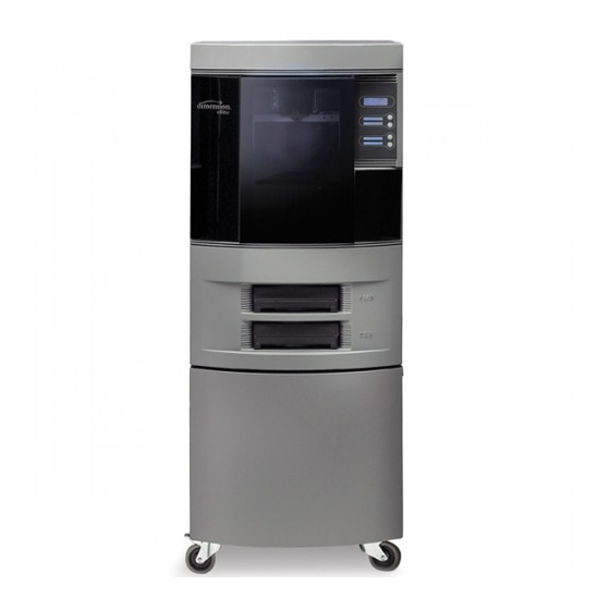
Stratasys Dimension 768/Elite Manuals
Manuals and User Guides for Stratasys Dimension 768/Elite. We have
3
Stratasys Dimension 768/Elite manuals available for free PDF download: Service Manual, Site Preparation Manual, Quick Start Manual
Stratasys Dimension 768/Elite Service Manual (713 pages)
Brand:
Stratasys
| Category:
3D Printers
| Size: 13 MB
Table of Contents
Table of Contents
4
Safety
10
Hazard Classifications
10
Product Safety Symbols
10
Safety Devices
10
Electronics Overview
12
Dimension 768 and Elite Specifications
14
What Happens When
15
Powering up
15
Powering down
15
Loading Material
15
Making a Part
16
A System Error Occurs
16
Gen 1 Electronics
17
186 Processor Board
17
186 Microprocessor Overview
17
Dual Port Memory Interface
17
X,Y,Z Axis Control
17
Filament Motor Control
18
Chamber Temperature Control
18
Liquefier Temperature Control
18
Actuators, Switches & Optical Sensors
19
Safety Devices
19
Watch Dog Timer (WDT)
19
186 Board Layout
20
Reset Button
20
Dip Switches
20
Memory
21
Led's
21
Single Board Computer
22
Power Distribution Board (PDB)
24
Motor Driver Board
26
Overview
26
Power/Voltages
26
Gen 2 Electronics
28
Electronics Overview
28
Controller Board
29
Overview
29
Voltage Generation
29
Dual Port Memory Interface
29
X, Y, Z Axis Control
29
Filament Motor Control
29
Temperature Control
29
Liquefier Temperature Control
29
Actuators, Switches & Optical Sensors
31
Safety Devices
31
Controller Board Layout
31
Reset Button
32
Dip Switches
32
Memory
33
Leds
34
Power Distribution Board (PDB)
35
Chamber Temperature Control
36
Test Points
36
Gen 3 Electronics
40
Electronics Overview
40
Controller Board
41
Overview
41
Voltage Generation
41
Dual Port Memory Interface
41
X, Y, Z Axis Control
41
Filament Motor Control
41
Temperature Control
41
Liquefier Temperature Control
41
Actuators, Switches & Optical Sensors
43
Safety Devices
43
Controller Board Layout
43
Reset Button
44
Dip Switches
44
Memory
45
Leds
45
Single Board Computer
46
Power Distribution Board (PDB)
47
Chamber Temperature Control
48
Test Points and Led's
48
Software
52
Software Architecture
53
Datastat
55
Catalystex Help
56
Maraca Help
58
System Software
64
Troubleshooting
66
Troubleshooting a System Malfunction
68
Overview
68
Testing the 186 Processor Board
68
Testing the Hard Drive and SBC
69
Final Test
69
Fault Determination Codes
71
Cycling Power
71
Diagnosing Loss of Extrusion
72
Clogged Tip
73
Service Troubleshooting
74
Code Errors
75
Major Codes
75
Major Codes with Minor Codes
76
Controller Abort Minor Errors (Code: 14, XX)
76
Starting up Failed Minor Errors (15.XX)
88
Controller Load Failed Minor Errors (17.XX)
88
Temperature Failed to Regulate Minor Errors (18.XX)
89
Controller Initialization Failed Minor Errors (19.XX)
90
Door Unlatch Failed (20.XX)
90
Controller Communications Failed Sub Errors (22.XX)
90
Unique Device Name Error (23.XX)
90
Non-Code Errors
91
Build Error" Displayed on LCD
92
Tip Depth Is Incorrect
92
Corrupted Upgrade" Displayed on LCD
92
Cartridge Invalid or Empty" Displayed on LCD
92
Door Latch
92
Door Open" Displayed on LCD
93
Download
93
Loss of Extrusion (LOE)
93
Lights
94
Material/Unload Error
94
Network Communication
95
Pauses During Build
96
What Happens During Power up / Boot
97
Power up / Boot
98
Can't Find Home - Check Modeling Base" Displayed on LCD
99
Power down
100
System very Slow to Reach Temperature
100
Calibration Issues
100
Z Calibration Failure
100
Noise
102
Part Quality Troubleshooting
103
Embedded Support Strands in Model
103
Brown Streaks (Burn Marks)
104
Loss of Extrusion (LOE)
105
Model Embedded in to Support
106
Moisture in Material
107
Open Seams
108
Part Curling
109
Part Fell over
110
Part Shifting
111
Rough Surface Quality
112
Rough Quality All over
113
Model Strands on Parts
114
Witness Marks
114
Wavy Surface
115
Wavy Parts
116
Under Fill
117
Material Sagging on Curved Parts
118
Fused Layers
119
Z Layers Inconsistent
120
Hyperterminal
121
Service Procedures
138
Exterior Components
146
Rear Door
146
Removing the Rear Door
146
Installing the Rear Door
147
Side Panels
148
Removing the Side Panels for Serial Numbers Less than P04746
148
Installing the Side Panels for Serial Numbers Less than P04746
149
Removing the Side Panels for Serial Numbers Greater than P04746
149
Installing the Side Panels for Serial Numbers Greater than P04746
149
Front Bezel
150
Removing the Front Bezel
150
Installing the Front Bezel
157
Display Panel
158
Removing the Display Panel
158
Installing the Display Panel
160
Door Solenoid
161
Removing the Door Solenoid
161
Installing the Door Solenoid
162
Door Sensor
163
Removing the Door Sensor
163
Installing the Door Sensor
164
Gen 3 Electrical Components
165
Power Distribution Board (PDB)
165
Removing the Power Distribution Board
166
Installing the Power Distribution Board
174
Controller Board
175
Removing the Controller Board
176
Installing the Controller Board
179
Single Board Computer (SBC)
180
Removing the IDE Single Board Computer
181
Installing the IDE Single Board Computer
183
Removing the SATA Single Board Computer
184
Installing the SATA Single Board Computer
186
Hard Drive
187
Removing the IDE Hard Drive
187
Installing the IDE Hard Drive
189
Removing the SATA Hard Drive
190
Installing the SATA Hard Drive
191
Electronics Bay Cooling Fan
193
Removing the Electronics Bay Cooling Fan
193
Installing the Electronics Bay Cooling Fan
194
24 VDC Power Supply
195
Removing the 24 VDC Power Supply
195
Installing the 24 VDC Power Supply
198
VDC Power Supply (SST Only)
200
Removing the 120 VDC Power Supply
200
Installing the 120 VDC Power Supply
202
5/12 VDC Power Supply
203
Removing the 5/12 VDC Power Supply
203
Installing the 5/12 VDC Power Supply
205
Line Filter Board
206
Removing the Line Filter Board
206
Installing the Line Filter Board
208
AC Input
209
Removing the AC Input
209
Installing the AC Input
211
Circuit Breaker
212
Removing the Circuit Breaker
212
Installing the Circuit Breaker
215
Gen 2 Electrical Components
216
Power Distribution Board (PDB)
216
Removing the Power Distribution Board
217
Installing the Power Distribution Board
224
Controller Board
225
Removing the Controller Board
226
Installing the Controller Board
229
Single Board Computer (SBC)
230
Removing the Single Board Computer
231
Installing the Single Board Computer
234
Hard Drive
235
Removing the Hard Drive
235
Installing the Hard Drive
237
Electronics Bay Cooling Fan
238
Removing the Electronics Bay Cooling Fan
238
Installing the Electronics Bay Cooling Fan
239
24 VDC Power Supply
240
VDC Power Supply (SST Only)
245
5/12 VDC Power Supply
248
Line Filter Board
251
AC Input
254
Circuit Breaker
257
Gen 1 Electrical Components
261
Power Distribution Board (PDB)
261
186 Processor Board
265
Single Board Computer (SBC)
270
VDC Piggyback Power Supply
273
24 VDC Power Supply
280
Removing the 24 VDC Power Supply
280
Dual 48 VDC Power Supplies (SST Only)
293
Motor Driver Board (MDB)
299
Hard Drive
304
Line Filter
310
Removing the Line Filter
310
Installing the Line Filter
313
AC Input
314
Removing the AC Input
314
Installing the AC Input
317
Circuit Breaker
318
Removing the Circuit Breaker
318
Installing the Circuit Breaker
320
Head Components
321
Head Cooling Fan
321
Installing the Head Cooling Fan
324
Head Temperature Snap Switch
325
Removing the Head Temperature Snap Switch
325
Installing the Head Temperature Snap Switch
327
BST Swivel Head
329
Removing the BST Swivel Head
329
Installing the BST Swivel Head
333
SST Swivel Head
334
Removing the SST Swivel Head
334
Installing the SST Swivel Head
339
TC Amp Board
340
Removing the TC Amp Board for SST
340
Installing the TC Amp Board for SST
343
Removing the TC Amp Board for BST
343
Umbilical Cable
346
Removing the Umbilical Cable
346
Installing the Umbilical Cable
358
Z Foam Level Sensor
359
Removing the Z Foam Level Sensor
359
Installing the Z Foam Level Sensor
360
Z Foam Level Assembly
361
Removing the Z Foam Level Assembly
361
Installing the Z Foam Level Assembly
362
Chamber Thermal Snap Switch
363
Removing the Chamber Thermal Snap Switch for Cable Drive XY Table
363
Installing the Chamber Thermal Snap Switch for Cable Drive XY Table
364
Removing the Chamber Thermal Snap Switch for Belt Drive XY Table
365
Installing the Chamber Thermal Snap Switch for Belt Drive XY Table
367
XY Table Cable Drive Components
368
EOT (End of Travel) Limit Switch
368
Removing the X EOT Switch
368
Installing the X EOT Switch
369
BOT (Home) Sensor
370
Removing the X BOT Sensor
370
Installing the X BOT Sensor
372
Y EOT (End of Travel) Limit Switch
373
Removing the y EOT Switch
373
Installing the y EOT Switch
375
Y BOT (Beginning of Travel) Sensor
376
Installing the y BOT Sensor
378
XY Table Assembly (Cable Drive)
379
Removing the XY Table Assembly
379
Installing the XY Table Assembly
387
XY Table Belt Drive Components
394
BOT (Home) Sensor (Belt Drive)
394
Removing the X BOT Sensor
394
Installing the X BOT Sensor
396
EOT (End of Travel) Sensor (Belt Drive)
397
Removing the X EOT Sensor
397
Installing the X EOT Sensor
399
Motor (Belt Drive)
400
Removing the X Motor
400
Installing the X Motor
402
Motor Belt (Belt Drive)
403
Removing the X Motor Belt
403
Installing the X Motor Belt
407
Drive Belt (Belt Drive)
411
Removing the X Drive Belt
411
Installing the X Drive Belt
413
Y BOT (Home) Sensor (Belt Drive)
415
Removing the y BOT (Home) Sensor
415
Installing the y BOT (Home) Sensor
417
Y EOT (End of Travel) Sensor (Belt Drive)
418
Removing the y EOT Sensor
418
Installing the y EOT Sensor
420
Y Motor (Belt Drive)
421
Removing the y Motor
421
Installing the y Motor
423
Y Motor Belt (Belt Drive)
424
Removing the y Motor Belt
424
Installing the y Motor Belt
425
Y Drive Belt (Belt Drive)
427
Removing the Right Side y Drive Belt
427
Installing the Right Side y Drive Belt
433
Removing the Left Side y Drive Belt
437
Installing the Left Side y Drive Belt
442
Y Pulley (Belt Drive)
446
Removing the Right Side y Pulley
446
Installing the Right Side y Pulley
449
Removing the Left Side y Pulley
452
Installing the Left Side y Pulley
455
Y Drive Assembly (Belt Drive)
459
Removing the y Drive Assembly
459
Installing the y Drive Assembly
465
XY Table Assembly (Belt Drive)
471
Removing the XY Table Assembly
471
Installing the XY Table Assembly
484
Z Stage Components
490
Thermostat Snap Switch
490
Removing the Thermostat Snap Switch
490
Installing the Thermostat Snap Switch
493
Tip Wipe Assembly
494
Replacing the Flicker Blade
494
Replacing the Brush
495
Z Stage Components - 3 Lead Screw
496
Chamber Thermocouple (3 Lead Screw)
496
Removing the Chamber Thermocouple
496
Installing the Chamber Thermocouple
498
Chamber Heaters (3 Lead Screw)
499
Removing the Left Side Chamber Heaters
499
Installing the Left Side Chamber Heaters
502
Removing the Right Side Chamber Heaters
503
Installing the Right Side Chamber Heaters
506
Z Switches (3 Lead Screw)
507
Removing the Z BOT (Home) Switch
507
Installing the Z BOT (Home) Switch
511
Removing the Z EOT Switch
513
Installing the Z EOT Switch
517
Z Jam Sensor (3 Lead Screw)
519
Removing the Z Jam Sensor
519
Installing the Z Jam Sensor
522
Z Motor Belt (3 LS)
523
Removing the Z Motor Belt
523
Installing the Z Motor Belt
526
Z Stage Motor (3 Lead Screw)
531
Removing the Z Motor
531
Installing the Z Motor
535
Z Stage Bearings (3 Lead Screw)
541
Removing the Z Stage Bearings
541
Installing the Z Stage Bearings
550
Z Foam Retainers
558
Removing the Z Foam Retainers
558
Installing the Z Foam Retainers
558
Z Stage Components (1 Lead Screw)
560
Chamber Thermocouple (1 Lead Screw)
560
Removing the Chamber Thermocouple
560
Installing the Chamber Thermocouple
562
Chamber Fans (1 Lead Screw)
563
Installing the Left Side Chamber Fans
565
Removing the Right Side Chamber Fans
566
Installing the Right Side Chamber Fans
568
Chamber Heaters (1 Lead Screw)
569
Removing the Left Side Chamber Heater
569
Installing the Left Side Chamber Heater
571
Removing the Right Side Chamber Heater
572
Installing the Right Side Chamber Heater
574
Z Jam Sensor (1 Lead Screw)
575
Removing the Z Jam Sensor
575
Installing the Z Jam Sensor
578
Z Sensors (1 Lead Screw)
579
Removing the Z BOT (Home) Sensor
579
Installing the Z BOT (Home) Sensor
581
Removing the Z EOT Sensor
581
Installing the Z EOT Sensor
583
Z Motor Belt (1 Lead Screw)
584
Removing the Z Motor Belt
584
Installing the Z Motor Belt
587
Z Motor (1 Lead Screw)
588
Removing the Z Motor
588
Installing the Z Motor
590
Z Stage Assembly - 1 LS
591
Removing the Z Stage Assembly
591
Installing the Z Stage Assembly
600
Receiver Components
607
Galvanized Receiver Assembly
607
Removing the Galvanized Receiver Assembly
607
Installing the Galvanized Receiver Assembly
612
Galvanized Receiver Plate
613
Removing the Galvanized Receiver Plate
613
Installing the Galvanized Receiver Plate
615
Calibrations & Adjustments
616
Tip Depth Calibration
617
Leveling the Liquefier
619
Tip Offset Calibration
623
Y Lash
626
Part Based Calibration
627
Tensioning the XY Cable Table
632
Leveling the XY Table (Cable Drive)
638
Leveling the XY Table (Belt Drive for 3 LS)
644
Tensioning the X & y Motor Belts (Belt Table)
646
Tensioning the X & y Drive Belts (Belt Table)
650
Leveling the XY Table (Belt Drive)
663
Adjusting Z BOT (Home) Switch
668
Get/Send Calibration Files
672
Z Tray Leveling (Cantilever Z Stage, Foam)
674
Leveling the Z Platen
676
Aligning Single Lead Screw Z Stage
679
Preventive Maintenance
680
Daily Maintenance
681
Startup Kit
681
Weekly Maintenance
682
Quarterly Maintenance
682
As Needed Maintenance
683
Index
684
120/240 VAC Jumper Configuration
702
Appendix
702
Fuse Specifications
703
Device Voltages
704
Hard Drive Installation Checklist
705
XY Table Installation Checklist
706
Head Installation Checklist
707
Pre-Installation Checklist
708
System Installation Checklist
709
Training Checklist
710
Required Tool List
712
Advertisement
Stratasys Dimension 768/Elite Site Preparation Manual (12 pages)
Brand:
Stratasys
| Category:
3D Printers
| Size: 0 MB
Table of Contents
Table of Contents
3
About the Dimension Elite Printer
5
Components
5
Highlights
5
How to Use this Guide
5
Site Prep Tasks
6
Selecting the Site
6
Space Requirements
6
Uncrated Dimensions and Weights
6
Minimum Clearances
6
Environmental Requirements
6
Power Consumption
7
Workstation Requirements
7
Electrical Requirements
7
AC Power Requirements
7
Lan Requirements
7
Uninterruptible Power Supply (Ups)
8
Use and Installation
8
General Information
8
Parts List - Cable, UPS to 3D Printer
9
Receiving the Printer
11
Inspect Crate for Damage
11
Preparing for Installation
11
Required Tools and Equipment
11
Unpacking the Printer
11
Site Preparation Checklist
11
Electrical Installation Requirements
11
Environmental Requirements
11
Stratasys Dimension 768/Elite Quick Start Manual (7 pages)
Head Clog Clearing
Brand:
Stratasys
| Category:
3D Printers
| Size: 2 MB
Table of Contents
Step 1: Gather the Appropriate Tools
1
Step 2: Turn the Machine on and Allow It to Boot up
1
Step 3: Open the Head
2
Step 4: Remove the Feed Funnel
2
Step 5: Unscrew the Two Motor Screws
3
Step 6: Remove the Motor
3
Step 7: Remove any Excess Material
3
Step 8: Brush any Material Away from the Drive Wheel
4
Step 9: Reattach the Drive Motor
4
Step 10: Reattach the Feed Funnel
5
Step 11: Run the Model Motor Forward
5
Step 12: Detach the Support Motor
5
Step 13: Run the Support Drive Motor in Reverse
6
Step 14: Reattach the Motor and Feed Funnel
6
Advertisement
Advertisement
Related Products
Stratasys Dimension Elite
Stratasys Dimension BST 1200
Stratasys Dimension SST 1200
Stratasys Dimension 1200es
Stratasys Dimension 1200
Stratasys 155-01200
Stratasys 155-01400
Stratasys 180-00108 uPrint
Stratasys 180-00109 uPrint
Stratasys 180-00110 uPrint
Stratasys Categories
3D Printers
Ultrasonic Jewelry Cleaner
Scrubber
UPS
Cleaning Equipment
More Stratasys Manuals
Login
Sign In
OR
Sign in with Facebook
Sign in with Google
Upload manual
Upload from disk
Upload from URL