
ST STM32U5 Manuals
Manuals and User Guides for ST STM32U5. We have 5 ST STM32U5 manuals available for free PDF download: Application Note, User Manual, Getting Started

ST STM32U5 Application Note (56 pages)
Brand: ST
|
Category: Microcontrollers
|
Size: 3 MB
Table of Contents
Advertisement
ST STM32U5 User Manual (49 pages)
Brand: ST
|
Category: Computer Hardware
|
Size: 5 MB
Table of Contents

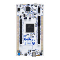
ST STM32U5 User Manual (49 pages)
Nucleo-144 board MB1549
Brand: ST
|
Category: Motherboard
|
Size: 2 MB
Table of Contents
Advertisement

ST STM32U5 Getting Started (47 pages)
MCU Hardware development
Brand: ST
|
Category: Computer Hardware
|
Size: 2 MB
Table of Contents

ST STM32U5 User Manual (22 pages)
security guidance for SESIP level 3 certification
Brand: ST
|
Category: Computer Hardware
|
Size: 0 MB
Table of Contents
Advertisement