Sign In
Upload
Manuals
Brands
ST Manuals
Computer Hardware
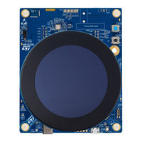
STM32U5A9J-DK
ST STM32U5A9J-DK Manuals
Manuals and User Guides for ST STM32U5A9J-DK. We have
2
ST STM32U5A9J-DK manuals available for free PDF download: User Manual
ST STM32U5A9J-DK User Manual (71 pages)
Brand:
ST
| Category:
Computer Hardware
| Size: 18 MB
Table of Contents
Figure 1. STM32U5G9J-DK1 Top View
1
Figure 2. STM32U5G9J-DK1 Bottom View
1
Features
2
Ordering Information
3
Codification
3
Table 1. List of Available Products
3
Table 2. Codification Explanation
3
Development Environment
4
System Requirements
4
Development Toolchains
4
Demonstration Software
4
Laser Consideration
5
Figure 3. Class 1 Laser Product Label
5
Conventions
6
Table 3. ON/OFF Convention
6
Quick Start
7
Hardware Layout and Configuration
8
Hardware Block Diagram
8
Figure 4. Hardware Block Diagram
8
Product Layout
9
Figure 5. Main Board Top Layout View
9
Figure 6. Main Board Bottom Layout View
10
Figure 7. LCD Daughterboard Top Layout View
11
Figure 8. LCD Daughterboard Bottom Layout View
12
Mechanical Drawings
13
Figure 9. Main Board Top
13
Figure 10. Main Board Bottom
14
Figure 11. LCD Daughterboard Top
15
Figure 12. LCD Daughterboard Bottom
16
Embedded STLINK-V3E
17
Figure 13. Default Configuration to Use STLINK-V3E
17
STLINK-V3E Deactivation (Reset Mode)
18
STLINK-V3E TNRST Disconnection
18
Table 4. STLK_NRST Configuration (JP6)
18
Table 5. TNRST Configuration (JP5)
18
Figure 14. STLK_NRST Default Configuration (JP6)
18
Figure 15. TNRST Default Configuration (JP5)
18
Drivers
19
STLINK-V3E VCP Configuration
19
STLINK-V3E I/O Interface
19
Table 6. STLINK-V3E I/O Interface
19
Figure 16. USB Composite Device
19
Power Supply
20
Power Diagram
20
Figure 17. Power Diagram
21
Power Source Selection
22
STLK (for Compatibility with USB Host Port Legacy)
22
Table 7. 5V Selection Configuration Jumper (JP4)
22
Figure 18. STLK (JP4) from USB STLK (CN5)
22
Chgr
23
Usbc
23
Figure 19. CHGR (JP4) from USB STLK (CN5)
23
Figure 20. USBC (JP4) from USB Type-C ® (CN4)
23
E5V
24
Microcontroller Power
24
Figure 21. E5V (JP4) from 5V_IN/GND (CN9)
24
Vdd_Mcu
25
Internal SMPS
25
Analog Power Supplies
25
Table 8. IDD Configuration (JP1, JP2, and JP3)
25
Figure 22. Jumpers Default Configuration (JP1, JP2, and JP3)
25
Other Peripheral Power
26
Clock Sources
27
Boot Options
28
Figure 23. BOOT0 Default Configuration, Set on "0" (SW1)
28
Board Functions
29
Round TFT DSI LCD Daughterboard and DSI_V3 Connector
29
Display Management
29
Touch-Panel Management
29
Display and DSI_V3 I/O Interface
30
Other DSI_V3 Compatible Peripherals
30
Table 9. 2.47" Display and DSI_V3 I/O Interface
30
USB Type-C ® (High Speed, Sink Only)
31
USB Type-C ® Sink Only
31
USB 2.0 High-Speed Interface
32
USB Type-C ® Function Interface
32
Table 10. Ucpd.adcx Voltage Range and Threshold According to Power Source Capability
32
Table 11. USB Type-C ® Function Interface
32
Hexadeca-SPI PSRAM Memory
33
Table 12. Hexadeca-SPI PSRAM I/O Interface
33
Octo-SPI Flash Memory
34
Emmc Flash Memory
34
Audio Codec (Not Used)
34
Table 13. Octo-SPI Flash Memory I/O Interface
34
Table 14. Emmc Flash Memory I/O Interface
34
20-Pin Audio MEMS Connector
35
Time-Of-Flight Sensor
35
Table 15. Audio Codec I/O Interface
35
Table 16. 20-Pin Audio MEMS Connector Function I/O Interface
35
Temperature Sensor
36
Expansion Connectors
36
Table 17. Tof Sensor I/O Interface
36
Table 18. Temperature Sensor I/O Interface
36
Figure 24. Class 1 Laser Product Label
36
User Button Function
37
Reset Button and Reset Function
37
Buttons and Leds Function
38
Table 19. Buttons and Leds
38
SWD Debug/Program/Trace and JTAG/USART
39
User Constraints for CN11 and CN3 Connectors
39
Table 20. Debug/Program/Trace and JTAG/USART Interface Overview
39
SWD, SWO, JTAG, and USART I/O Interface
40
Table 21. SWD, SWO, JTAG, and USART Function I/O Interface
40
Connectors
41
USB Type-C ® Receptacle Connector (CN4)
41
Table 22. USB Type-C ® Receptacle Connector (CN4)
41
Figure 25. USB Type-C ® Receptacle Connector (Front View) (CN4)
41
Figure 26. USB Type-C ® Connector Pinout (CN4)
41
Figure 27. USB Type-C ® Top Layer Footprint Pinout (CN4)
41
Debug Connector (CN11)
42
MIPI10 Debug Connector (Default Configuration)
42
Figure 28. MIPI10 Debug Connector (CN11)
42
STDC14 Debug Connector (Option)
43
Table 23. MIPI10 on STDC14 Footprint
43
Table 24. STDC14 Connector Pinout
43
Figure 29. STDC14 Debug Connector (CN11)
43
TAG Connector (CN3)
44
Table 25. TAG Connector Pinout
44
Figure 30. TAG Connector (CN3)
44
Figure 31. 10-Pin Compatible Cable Example
44
DSI_V3 Display Board Connector (CN2)
45
Table 26. DSI_V3 Connector Pin Assignment (CN2)
45
Figure 32. DSI_V3 Display Connector (CN2)
45
Audio Jack (Not Used) (CN6)
46
Figure 33. Audio Jack Connector (CN6)
46
STLINK-V3E USB Micro-B Connector (CN5)
47
Table 27. Audio Jack (CN6) Pinout
47
Table 28. USB Micro-B (CN5) Pinout
47
Figure 34. USB Micro-B Connector (CN5)
47
Expansion Connectors (CN9 and CN10)
48
Pin Assignment and Connectors
48
Table 29. Connector Pinout (Bottom View) (CN9)
48
Figure 35. Female Expansion Connectors (CN9 and CN10)
48
Table 30. Connector Pinout (Bottom View) (CN10)
49
20-Pin Audio MEMS Connector (CN1)
50
Table 31. 20-Pin Audio MEMS Connector Pinout (CN1)
50
Figure 36. 20-Pin Audio MEMS Connector (CN1)
50
Jumpers and Solder Bridges
51
Jumpers
51
Table 32. Jumper Configuration
51
Solder Bridges
52
Table 33. Solder Bridge Configuration
52
Stm32U5X9Njh6Q GPIO and Pin Assignment
56
Table 34. Stm32U5X9Njh6Q GPIO and Pin Assignment
56
Stm32U5X9J-Dkx Product Information
61
Product Marking
61
Stm32U5X9J-Dkx Product History
62
Table 35. Product History
62
Board Revision History
63
Table 36. Board Revision History
63
Federal Communications Commission (FCC) and ISED Canada Compliance
64
Statements
64
FCC Compliance Statement
64
ISED Compliance Statement
64
Revision History
65
Table 37. Document Revision History
65
Table of Contents
66
List of Tables
69
List of Figures
70
Advertisement
ST STM32U5A9J-DK User Manual (68 pages)
Brand:
ST
| Category:
Computer Hardware
| Size: 6 MB
Table of Contents
Figure 1. STM32U5A9J-DK Top View
1
Figure 2. STM32U5A9J-DK Bottom View
1
Features
2
Ordering Information
3
Codification
3
Table 1. List of Available Products
3
Table 2. Codification Explanation
3
Development Environment
4
System Requirements
4
Development Toolchains
4
Laser Consideration
5
Figure 3. Class 1 Laser Product Label
5
Conventions
6
Table 3. ON/OFF Convention
6
Quick Start
7
Hardware Layout and Configuration
8
Hardware Block Diagram
8
Figure 4. Hardware Block Diagram
8
Product Layout (Top and Bottom)
9
Figure 5. STM32U5A9J-DK Top Layout View
9
Figure 6. STM32U5A9J-DK Bottom Layout View
10
Mechanical Drawings
11
Main Board Top
11
Figure 7. MB1829 Top
11
Main Board Bottom
12
Figure 8. MB1829 Bottom
12
Daughterboard Top
13
Figure 9. MB1835 Top
13
Daughterboard Bottom
14
Figure 10. MB1835 Bottom
14
Embedded STLINK-V3E
15
Figure 11. Default Configuration to Use STLINK-V3E
15
STLINK-V3E Deactivation (Reset Mode)
16
STLINK-V3E TNRST Disconnection
16
Table 4. JP6 STLK_NRST Configuration
16
Table 5. JP5 TNRST Configuration
16
Figure 12. JP6 STLK_NRST Default Configuration
16
Figure 13. JP5 TNRST Default Configuration
16
Drivers
17
STLINK-V3E VCP Configuration
17
STLINK-V3E I/O Interface
17
Table 6. STLINK-V3E I/O Interface
17
Figure 14. USB Composite Device
17
Power Supply
18
Power Diagram
18
Figure 15. Power Diagram
19
Power Source Selection
20
STLK (for Compatibility with USB Host Port Legacy)
20
Table 7. 5V Selection Configuration Jumper (JP4)
20
Figure 16. STLK (JP4) from USB STLK (CN5)
20
Chgr
21
Usbc
21
Figure 17. CHGR (JP4) from USB STLK (CN5)
21
Figure 18. USBC (JP4) from USB Type-C ® (CN4)
21
E5V
22
Microcontroller Power
22
Figure 19. E5V (JP4) from 5V_IN/GND (CN9)
22
Vdd_Mcu
23
Internal SMPS
23
Analog Power Supplies
23
Table 8. IDD Configuration (JP1, JP2, and JP3)
23
Figure 20. Jumpers Default Configuration (JP1, JP2, and JP3)
23
Other Peripheral Power
24
Clock Sources
25
Boot Options
26
Figure 21. BOOT0 Default Configuration, Set on "0" (SW1)
26
Board Functions
27
Round TFT DSI Display Module Board and DSI_V3 Connector
27
Display Management
27
Touch-Panel Management
27
Display and DSI_V3 I/O Interface
28
Other DSI_V3 Compatible Peripherals
28
Table 9. 2.47" Display and DSI_V3 I/O Interface
28
USB Type-C (High Speed, Sink Only)
29
USB Type-C ® Sink Only
29
USB 2.0 High-Speed Interface
30
USB Type-C ® Function Interface
30
Table 10. Ucpd.adcx Voltage Range and Threshold According to Power Source Capability
30
Table 11. USB Type-C ® Function Interface
30
Table 33. Solder Bridge Configuration
30
Hexadeca-SPI PSRAM Memory
31
Table 12. Hexadeca-SPI PSRAM I/O Interface
31
Octo-SPI Flash Memory
32
Emmc Flash Memory
32
Table 13. Octo-SPI Flash I/O Interface
32
Audio Codec (Not Used)
33
20-Pin Audio Connector (Not Used)
33
Table 14. Emmc Flash I/O Interface
33
Table 15. Audio Codec I/O Interface
33
Time-Of-Flight Sensor
34
Table 16. 20-Pin Audio Function I/O Interface
34
Table 17. Tof Sensor I/O Interface
34
Figure 22. Class 1 Laser Product Label
34
Temperature Sensor
35
Expansion Connectors
35
User Button Function
35
Table 18. Temperature Sensor I/O Interface
35
Reset Button and Reset Function
36
Buttons and Leds Function
36
Table 19. Buttons and Leds
36
SWD Debug/Program/Trace and JTAG/USART
37
User Constraints for CN11 or CN3 Connectors
37
Table 20. Debug/Program/Trace and JTAG/USART Interface Overview
37
SWD, SWO, JTAG, and USART I/O Interface
38
Table 21. SWD, SWO, JTAG, and USART Function I/O Interface
38
Connectors
39
USB Type-C ® Receptacle Connector (CN4)
39
Table 22. USB Type-C ® Receptacle Connector (CN4)
39
Figure 23. USB Type-C ® Receptacle Connector (Front View) (CN4)
39
Figure 24. USB Type-C ® Connector Pinout (CN4)
39
Debug Connector (CN11)
40
MIPI10 Debug Connector (Default Configuration)
40
Figure 25. MIPI10 Debug Connector (CN11)
40
STDC14 Debug Connector (Option)
41
Table 23. MIPI10 on STDC14 Footprint
41
Table 24. STDC14 Connector Pinout
41
Figure 26. STDC14 Debug Connector (CN11)
41
TAG Connector (CN3)
42
Table 25. TAG Connector Pinout
42
Figure 27. TAG Connector (CN3)
42
Figure 28. TC2050-IDC-NL Cable
42
DSI_V3 Display Board Connector (CN2)
43
Table 26. DSI_V3 Connector Pin Assignment (CN2)
43
Figure 29. DSI_V3 Display Connector (CN2)
43
Audio Jack (Not Used) (CN6)
44
Figure 30. Audio Jack Connector (CN6)
44
STLINK-V3E USB Micro-B Connector (CN5)
45
Table 27. Audio Jack (CN6) Pinout
45
Table 28. USB Micro-B (CN5) Pinout
45
Figure 31. USB Micro-B Connector (CN5)
45
Expansion Connectors (CN9 and CN10)
46
Pin Assignment and Connectors
46
Figure 32. Female Expansion Connectors (CN9 and CN10)
46
Table 29. Connector Pinout (Bottom View) (CN9)
47
Table 30. Connector Pinout (Bottom View) (CN10)
47
20-Pin Audio Connector (Not Used) (CN1)
48
Table 31. 20-Pin Audio Connector Pinout (CN1)
48
Figure 33. 20-Pin Audio Connector (CN1)
48
Jumpers and Solder Bridges
49
Jumpers
49
Table 32. Jumper Configuration
49
Solder Bridges
50
STM32U5A9NJH6Q GPIO and Pin Assignment
54
Table 34. STM32U5A9NJH6Q GPIO and Pin Assignment
54
STM32U5A9J-DK Product Information
59
Product Marking
59
STM32U5A9J-DK Product History
59
Table 35. Product History
59
Board Revision History
60
Table 36. Board Revision History
60
Federal Communications Commission (FCC) and Innovation, Science and Economic
61
Development Canada (ISED) Compliance Statements
61
FCC Compliance Statement
61
ISED Compliance Statement
61
Revision History
62
Table 37. Document Revision History
62
Table of Contents
63
List of Tables
66
List of Figures
67
Advertisement
Related Products
ST STM32U575 Series
ST STM32U585 Series
ST STM32U5
ST STM32U5A9NJ MCU
ST STM32U5 Nucleo-64
ST STM32U5G9J-DK2
ST STM32U5X9NJ
ST STM32U5G9J-DK1
ST STM32U083C-DK
ST STM32U3
ST Categories
Motherboard
Computer Hardware
Microcontrollers
Control Unit
Controller
More ST Manuals
Login
Sign In
OR
Sign in with Facebook
Sign in with Google
Upload manual
Upload from disk
Upload from URL