Sign In
Upload
Manuals
Brands
Simplex Manuals
Control Panel
4100+
Simplex 4100+ Manuals
Manuals and User Guides for Simplex 4100+. We have
4
Simplex 4100+ manuals available for free PDF download: Service Instructions Manual, Operating Instructions Manual, Manual, Operating Instructions
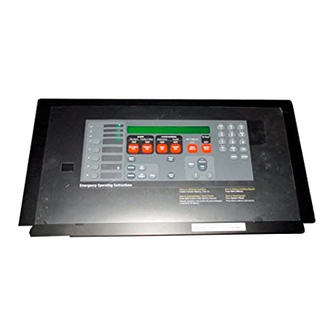
Simplex 4100+ Operating Instructions Manual (97 pages)
Brand:
Simplex
| Category:
Fire Alarms
| Size: 1 MB
Table of Contents
Table of Contents
3
Section 1 - System Overview
9
Introduction
9
System Operating Description
10
Interface Panel
10
Log in Procedure
11
Log out Procedure
12
Handling Abnormal Conditions
13
Introduction
15
Global Acknowledge Panel Operation During Alarm Conditions
15
Interface Panel Showing Alarm Condition
15
How to Silence the Alarm Signals
16
How to Reset the System
16
Individual Acknowledge Panel Operation During Alarm Conditions
16
How to Silence the Alarm Signals
17
How to Reset the System
17
Essential Alarm Condition Keys
17
Alarm Acknowledge Key
17
Alarm Silence Key
18
Alarm Silence Software Considerations
18
System Reset Key
19
If the Alarm Point Does Not Reset
19
How to Disable a Point
19
Introduction
21
Global Acknowledge Panel Operation During Trouble Conditions
21
Interface Panel Showing Trouble Condition
21
Individual Acknowledge Panel Operation During Trouble Conditions
22
Essential Trouble Condition Keys
23
Trouble Acknowledge Key
23
System Reset Key
24
If the Trouble Does Not Reset
24
How to Disable a Point with a Trouble Condition
24
Trouble Indications for Truealarm Sensors
25
Introduction
25
Almost Dirty Indication
26
Dirty Indication
26
Excessively Dirty Indication
26
Self-Test Abnormal Indication
26
Introduction
27
Global Acknowledge Panel Operation During Supervisory Service Conditions
27
Interface Panel Showing Supervisory Service Condition
27
Individual Acknowledge Panel Operation During Supervisory Service Conditions
28
Essential Supervisory Service Condition Keys
29
Supervisory Acknowledge Key
29
Introduction
31
RS-232 Port Access Levels
31
The Video Terminal
31
RS-232 Interface Default Protection Levels
31
CRT Function Key Definitions
32
Set-Up Procedure
32
CRT Screen Displays
32
CRT Main Menu Screen
32
Function Key Definitions
32
Acknowledge Screen
33
CRT Main Menu Screen
33
Log in Screen
34
CRT Acknowledge Screen
34
CRT Log in Screen
34
Historical Log Screen
35
Status Screen
35
CRT Alarm Historical Log Screen
35
CRT Status Screen
35
The System Printer
36
40-Character Line Width Printout
36
Section 6 - Network Interface
37
Introduction
37
Network (or 2120) Operation During Walk Test
37
Section 7 - Audio Systems
39
Introduction
39
General Information
39
Audio Features
39
System Operation
39
Audio System Configurations
39
Audio Control Led/Switch Module
40
Voice Messages
40
Voice Coded Digits
40
Preambles
40
Trouble Messages
41
Audio Walk Test
41
Walk Test Trouble Audible
41
Single Channel Audio Operations
41
Audio Control Led/Switch Module
41
ALL SPEAKERS EVAC Switch
42
SELECTIVE EVAC Switch
42
ALL SPEAKERS TALK Switch
42
LOCAL SPEAKER Switch
42
Audio Control Led/Switch Module for Single Channel Operations
42
Optional Functions
43
Speaker Select Switches
43
Single Channel Audio System Operation
43
How to Operate the Microphone Operation During Automatic Alarm Conditions
43
How to Manually Initiate an Evacuation Signal
44
Led/Switch Locations for Microphone Operation During Alarm Conditions (Single Channel)
44
Led/Switch Locations for Evacuation Signal Initiation (Single Channel)
44
How to Operate the Microphone During Non-Alarm Conditions
45
How to Use the Local Panel Speaker
45
Led/Switch Locations for Microphone Operation During Non-Alarm Conditions (Single Channel)
45
Led/Switch Locations for Local Panel Speaker Operation (Single Channel)
45
Dual Channel Audio Operations
46
Audio Control Led/Switch Module for Dual Channel Audio
46
ALL SPEAKERS EVAC Switch
46
SELECTIVE EVAC Switch
46
Audio Control Led/Switch Module for Dual Channel Operations
46
ALL SPEAKERS TALK Switch
47
LOCAL SPEAKER ALERT Switch
47
LOCAL SPEAKER EVAC Switch
47
Optional Functions
47
Speaker Select Switches and Leds
48
Dual Channel Audio System Operation
48
How to Operate the Microphone During Automatic Alarm Conditions
48
How to Manually Initiate an Evacuation Signal
49
Led/Switch Locations for Microphone Operation During Alarm Conditions (Dual Channel)
49
Led/Switch Locations for Evacuation Signal Initiation (Dual Channel)
49
How to Operate the Microphone During Non-Alarm Conditions
50
Triple Channel Audio Operations
50
Audio Control Led/Switch Module for Triple Channel Audio
50
Led/Switch Locations for Microphone Operation During Non-Alarm Conditions (Dual Channel)
50
Audio Control Led/Switch Module for Triple Channel Operations
50
ALL SPEAKERS EVAC Switch
51
SELECTIVE EVAC Switch
51
ALL SPEAKERS TALK Switch
51
LOCAL SPEAKER ALERT Switch
51
LOCAL SPEAKER EVAC Switch
51
Optional Functions
51
Speaker Select Switches and Leds
52
Triple Channel Audio System Operation
52
How to Operate the Microphone During Automatic Alarm Conditions
53
How to Manually Initiate an Evacuation Signal
53
Led/Switch Locations for Microphone Operation During Alarm Conditions (Triple Channel)
53
Led/Switch Locations for Evacuation Signal Initiation (Triple Channel)
53
How to Operate the Microphone During Non-Alarm Conditions
54
Led/Switch Locations for Microphone Operation During Non-Alarm Conditions (Triple Channel)
54
Telephone Operation
55
Phone Led/Switch Module
55
How to Operate the Telephone
55
Led/Switch Locations for Phone Circuit Operation
55
Optional Feature Operation
56
How to Initiate a Drill
56
How to Perform an All Clear Operation
56
Led/Switch Locations for Drill Initiation
56
Led/Switch Locations for Performance of an All Clear Operation
56
How to Operate Auxiliary Functions
57
How to Connect the Phone Line to the Audio System
57
Led/Switch Locations for Auxiliary Function Operation
57
Led/Switch Locations for Connection of Phone Line to Audio System
57
How to Use the Manual Audio Override Switch
58
How to Operate the All Speakers Minus Switch
58
Led/Switch Locations for Manual Override Switch Operation
58
Led/Switch Locations for All Speakers Minus Switch Operation
58
Section 8 - Mapnet II Addressable Interface
59
Introduction
59
Truealarm System Operation
59
Typical Truealarm Status Report Screen
60
Generating Truealarm Reports
61
MAPNET II Alphanumeric Displays
61
MAPNET II Point Addressing
62
Mapnet II
62
How to Display a MAPNET
62
What to Do if a MAPNET
62
Point will Not Reset
62
System Point
62
Section 9 - Advanced Functions
63
Introduction
63
Control Keys
63
Interface Panel Controls and Indicators
63
Function Keys
64
How to Set Time and Date
64
How to Escape from Menu
65
Point Control with the Function Key
66
Display/Action Keypad
66
FUNCTION Key
67
DISPLAY/ACTION Keypad
67
MENU Key
68
PREVIOUS Key
68
NEXT Key
68
LAMP TEST Key
68
Action Keys
69
ENTRY Keypad
69
How to Use Prefix Keys to Display System Points
69
How to Display the Sensitivity of a Truealarm Sensor
71
Typical Programmer's Report with Point Address Data
71
Additional Keys
73
Enter
73
CLR (Clear)
73
NET/-(Network/Hyphen)
73
DEL (Delete)
73
Viewing Power Supply/Charger Voltage and Current Readings
74
Point Selection
74
Selecting Points Using Lists
74
Selecting Points Using the Keypad
74
Selecting Additional Lists
75
Operator Access Levels
75
Power-Up Sequence
76
Section 10 - System Test Procedures
77
Lamp Test
77
Walk Test
77
Walk Test by Group
77
Zone Coding Option
78
Silent Walk Test
78
Entering Walk Test Mode
78
Walk Test Operation
79
Walk Test Features
79
Abort Audible and Delay on Reactivation
80
Active/Not Active
80
Audio Walk Test
80
Audio Zone Coding
80
Audio Zone/Signal Trouble
80
Auto Abort on Alarm
80
Auto Abort on Time-Out
80
Control List
80
Delay before Reset
81
Logging Option (Log/No Log)
81
Monitor Zone List
81
Programmer Configuration
81
Sig/No Sig (Silent Walk Test Selection)
81
System Trouble
81
Trouble Audible
82
Zone Code/Zero Code
82
Walk Test Procedures
82
How to Enter a Walk Test Passcode
82
How to Enter Walk Test Mode
83
How to Exit Walk Test Mode
84
How to Turn a Point off
84
How to Turn a Point on
85
How to Return a Point to AUTO
86
How to Enable a Disabled Point
87
What to Do in Case of System Malfunction
88
Appendix Abbreviated Operator Interface Procedures
89
Operator Log In/Log out Procedures
89
Access Level Log in Procedure
89
Access Level Log in Procedure from the CRT
90
Access Level Log out Procedure
90
Access Level Log out Procedure from the CRT
91
System Operating Procedures
91
Viewing a List of Points
91
Viewing the Status of any System Point
91
Controlling System Points
92
Viewing the Sensitivity of a Truealarm Sensor
92
Logging and Clearing an Analog Sensor Peak Value
92
Viewing the Historical Alarm and Trouble Logs
93
Clearing the Historical Alarm and Trouble Logs
93
Viewing Abnormal System Conditions with the Display Time Key
94
Clearing the Alarm Verification Tally
94
Viewing Power Supply/Charger Voltage and Current Readings
94
Generating Truealarm Reports
95
Advertisement
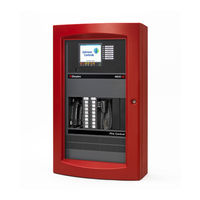
Simplex 4100+ Service Instructions Manual (98 pages)
Universal Transponder
Brand:
Simplex
| Category:
Fire Alarms
| Size: 6 MB
Table of Contents
Table of Contents
3
General
11
Master Controller Board
11
Master Motherboard (Termination Board)
11
Board Identification
11
Component Locations and Functions
11
Graphic Representation of Basic 4100 Fire Alarm System
12
Display Board
13
System Components, Detailed Descriptions
13
Master Controller Board (562-771)
13
Component Locations and Functions
13
Led1
13
IC Chips
14
Switches
14
Fuses
14
Master Controller Board
14
Master Controller
14
Jumpers
15
Coded Input Capacitors
15
Connectors
15
UT Master Controllers
16
Component Locations and Functions (565-333)
16
Led1
16
IC Chips
16
Sw1
16
Jumpers
16
Connectors
17
Component Locations and Functions (565148)
17
Led1
17
IC Chips
17
Sw1
18
Jumpers
18
Connectors
18
Master Motherboard Assembly
19
Board Identification
19
Style B (Class B) Master Motherboard
19
Connectors
20
Terminal Blocks
20
Style D (Class A) Master Motherboard
20
UT Master Motherboards
21
Connectors (565-L 61)
21
Terminal Blocks (565-161)
21
Connectors
22
Terminal Blocks (565-213)
22
City Connections
22
Master Power Supply
23
Internal Power and Communications
23
Master Power Supply (562-808)
23
UT Master Motherboard
23
Component Locations and Functions
24
Led1
24
Jumpers
24
Master Power Supply Board
24
Fuses
25
Potentiometers
25
Connectors and Connector Pins
25
Terminal Blocks
27
Display Board (562-795)
27
Component Locations and Functions
27
Potentiometer R2
27
Connectors
27
UT Master Display Board (565-L 73)
28
Component Locations and Functions
28
4100+ Master Display Board (565-331)
28
Potentiometer R2
28
Connectors
28
Display Board
28
Expansion Boards
29
Motherboards
29
Class a (Style D) and Class B (Style B) Motherboards
29
Mounting Space Required
29
Labeling
29
Class a (Style D) Motherboard with Suppression
29
Terminal Blocks
30
Connectors and Connector Sockets
30
Class B (Style B) Motherboard with Suppression
30
Daughter Cards for Class a (Style D) Motherboard Daughter Cards for Class B (Style B) Motherboard
31
32-Point Motherboard (562-727/562-858)
31
Connectors and Connector Sockets
31
Labeling
32
Terminal Blocks
32
Mounting Space Required
32
Compatible Daughter Cards
32
Amp Auxiliary Motherboard (562-952)
32
Connectors and Connector Sockets
32
Fuses
32
32-Point Motherboard
32
Relays
33
Labeling
33
Terminal Blocks
33
Compatible Daughter Card
33
MAPNET@ Power Supply/Motherboard (562-974)
34
Output Power Specifications
34
Labeling
34
Connectors and Connector Sockets
34
MAPNET@ Power Supply/Motherboard
34
Terminal Block (Tbl)
35
Mounting Space Required
35
Potentiometer R2
35
Jumpers
35
Compatible Daughter Card
35
Daughter Cards
35
8-Zone (8-Point) Monitor Card (562-813/562-731)
35
Features and Functions
36
Component Locations and Functions
36
Led1
36
Icl
36
Sw1
36
Connector
37
8-Zone (8-Point) Monitor Card
37
Jumpers
38
Features
38
Component Locations and Functions
38
Single Channel Signal Card
42
Multichannel Signal Card
42
64/64 Led/Switch Controller Board
45
Remote Annunciator Interface Card
46
Dual RS232/2120 Communication Board
49
Auxiliary Relay Card
49
24-Point Graphic I/O Interface Board
51
MAPNET@ Interface (Transceiver) Board
53
MAPNET@ Quad Isolator Board
54
Led/Switch Module
56
Remote Serial Interface Card
57
Remote Interface Card
58
Led1
60
Remote Unit Interface Card
60
Decoder Module
60
8-Amp Expansion Power Supply
62
5-Amp Expansion Power Supply
63
Charger Interface Module
68
Message Expansion Card
72
Backup Voice Tone Generator
73
Message Memory Board
74
Master Phone Controller
74
25-Watt Amplifier
77
Loo-Watt Amplifier
80
25-Watt Amplifier Power Supply
82
Intelligent Power Supply
85
Communicating Power Supply Controller Assembly
87
Master Power Supply Component Locations
90
Power Charger Card
91
Power Charger Card Component Locations
91
Audio Controller Board
92
Audio Controller Board Component Locations
92
25-Watt Amplifier Component Locations
93
Loo-Watt Amplifier Component Locations
94
Battery Test Requirements
96
Battery Disposition Guide
96
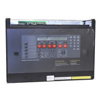
Simplex 4100+ Manual (60 pages)
Fire Products - Fault & Assistance Guide
Brand:
Simplex
| Category:
Control Panel
| Size: 1 MB
Table of Contents
Table of Contents
2
1 Identifying Simplex® 4100 Series Faults
4
4100 Series - Overview
5
4100U Basic Operations
6
Operator Interface Commands
7
Resetting 4100 Latched Faults & Rebooting CPU
8
Index - Quick View
9
Loop Card Faults
10
Card Missing/Failed
11
Correct Card Abnormal
11
Short Circuit Abnormal
11
Class 'A' Abnormal
12
Channel Failure Abnormal
12
Channel Initialization Abnormal
12
Extra Device
13
Addressable Device Faults
14
No Answer
14
Head Missing
15
Wrong Device
17
Bad Answer
17
Extra Device
18
Output Abnormal
19
Alarm Verification Tally Exceeded
19
Detector LED Operation
19
Device DIP Switch Settings
19
End of Line Resistors
20
4100-0157A Battery Charger Faults
22
Positive/Negative Earth Ground Faults
24
Earth Ground Fault Detecting and Locating
24
4100 Crash Codes - General Information
26
4100 Crash Codes - General Information
27
4100-Family General Crash Codes Table
28
4100-Family General Crash Codes Table (Continued)
29
3 Identifying Faults on the GCC, IMS & Truesite Graphics & Network
30
Identifying Faults on the Graphics - General Instructions
31
GCC, IMS & Truesite Workstation Graphical Control Centre
31
Displayed Fault Format
32
Fault Type
33
Network Faults
34
Common Trouble Point for Node
34
Card Trouble for Node
34
Network Operating in Degraded Style 7
34
Network Initialization Incomplete
34
Node Missing/Failed
34
System Pseudo Status for Node
34
Version Mismatch
34
4 Identifying F3200 Faults
35
Recall System Faults
36
Function
36
Operating Sequence
36
List of System Faults - Non-Networked
37
Glossary of Abbreviations
40
5 Identifying Faults on a QE90
42
Qe90 Service Isolation Mode - Fault Display
43
Ecp Versions 2
44
Audio Line Fault
45
Speaker Line Fault/Amp Fault
45
Amplifier LED Configurations
45
Speaker Tapping Adjustments
46
Strobe Line Fault
47
Strobe Output Considerations
47
Strobe Relay Driver Module and Strobe Light Connection
48
Cable Sizing
48
Links and DIP Switches
49
STBM9008 Board Installation
50
Bga or Fip Fault
51
Wip Line Fault
52
PA Speech, Spare Speech, WIP Speech, Comms and Spare Comms Cable Faults
53
Ecp Failures
54
MECP and SECP Failure
54
WIP MECP and SECP Failure
54
Paging Console Failure
54
Ecm Networked Systems
54
Ecm Networked System - System Fault Display
55
Qe90 Fault Register
56
6 National Contact Directory
59
Contact Us
60
Advertisement
Simplex 4100+ Operating Instructions (2 pages)
FIREFIGHTER'S AUDIO SYSTEM
Brand:
Simplex
| Category:
Stereo System
| Size: 0 MB
Table of Contents
How to Operate Microphone
1
How to Operate Phone
1
How to Initiate an Evacuation Signal
1
How to Reset the System
1
How to Silence Fire Alarm Signals
1
How to Use Local Speaker Switch
1
Your Safety and the Safety of those Around You
1
How to Use Local Speaker Alert Switch
2
How to Use Local Speaker Evac Switch
2
Advertisement
Related Products
Simplex SafeLINC 4100
Simplex MINIPLEX 4100ES Series
Simplex 4100-9401
Simplex 4100-9421
Simplex 4100-9441
Simplex 4100 Series
Simplex 4100A
Simplex 4100 Classic
Simplex 4100-9402
Simplex 4100-9422
Simplex Categories
Fire Alarms
Control Panel
Smoke Alarm
Control Unit
Security System
More Simplex Manuals
Login
Sign In
OR
Sign in with Facebook
Sign in with Google
Upload manual
Upload from disk
Upload from URL