Sign In
Upload
Manuals
Brands
Rockwell Automation Manuals
Controller
PowerFlex 7000
Rockwell Automation PowerFlex 7000 Manuals
Manuals and User Guides for Rockwell Automation PowerFlex 7000. We have
3
Rockwell Automation PowerFlex 7000 manuals available for free PDF download: Technical Data Manual, Instructions Manual, Tech Note
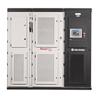
Rockwell Automation PowerFlex 7000 Technical Data Manual (351 pages)
Medium Voltage AC Drive
Brand:
Rockwell Automation
| Category:
Controller
| Size: 1.87 MB
Table of Contents
Table of Contents
3
Chapter 1 Powerflex 7000 Functional Description
5
Description of Operation
6
Functional Block Diagram of PF 7000 Control System
6
Speed Command
7
Speed Reference
8
Speed Reference: Linear Ramp
9
Speed Reference: S-Curve
9
Speed Control
10
Flux Control
12
Flux Control for Synchronous Motor
14
Current Control
16
Line Converter Feedback
18
Machine Converter Feedback
19
Motor Model
20
Drive/Motor Protection
21
Power Semiconductor Diagnostics
23
Off-Line Detection of Failed Scrs/Sgcts
24
Line Converter – 6P-SCR, 18P-SCR and PWM
24
SCR Rectifier Passive Off-Line Diagnostics
24
PWM Rectifier Passive Off-Line Diagnostics
24
Voltage Across a Thyristor When Medium Voltage Is Applied
25
Typical SGCT Gating Pattern
25
SCR Rectifier Active Off-Line Diagnostics
26
PWM Rectifier Active Off-Line Diagnostics
26
Machine Converter off Line Diagnostics
26
On-Line Detection of Failed Scrs/Sgcts
27
SCR On-Line Diagnostics
27
SGCT On-Line Diagnostics
27
Test Modes
28
Flying Start (Induction Motor)
30
Flying Start (Synch Motor)
31
Tachometer/Encoder Option
32
Synchronous Transfer
33
A Typical Synchronous Transfer Set up Using PF7000
34
Transfer to Bypass
35
Transfer to Drive
38
Dependent Gain Form
39
Independent Gain Form
39
PID Process Control
39
Process PID Controller
41
Analog Outputs
42
Power Factor Compensation
42
Analog Inputs
43
Introduction
5
Chapter 2 Parameters
45
Interpreting Bit-Encoded Parameters
45
Powerflex 7000/7000L Medium Voltage AC Drive
45
Bus Transient Level
54
Diagnostics Parameters
54
Maximum Value: 32.767 Pu
54
Minimum Value: 0.000 Pu
54
Drive Not Ready Status Word
55
Linear Number
55
Logic Status
55
Linear Number
56
Read/Write: Read Only
56
Access Level: Service
57
Read/Write: Read Only
57
Inverter Analog Self Test Code
61
Inverter Control Flags
61
Bypass Voltage Unbalance Value
65
Drive Overload Value
65
Motor Overload Value
65
Neutral Resistor Overload Value
65
Master Current Unbalance Value
66
Slave 1 Current Unbalance Value
66
Slave 1 Voltage Unbalance Value
66
Slave 2 Voltage Unbalance Value
66
Fault Output
67
Motor Current Unbalance Value
67
Motor Flux Unbalance Value
67
Warning Output
67
Feature Select Parameters
68
Operating Mode
68
Parameter Error
68
Speed Command Loss
69
Speed Reference Select
69
Automatic Restart Delay
70
Coast Speed
70
Input Contactor Configuration
70
Input Contactor Open Delay
70
Load Loss Detection
71
Output Contactor Configuration
71
Special Features
71
Inverter Gating Test
72
Rectifier Gating Test
72
Extended Trend
73
Setup Wizard
73
Fan 2 Run Time
74
PFC Access Code
74
Power Factor Compensation Method
74
DC Link Inductance
76
Drive Hardware Parameters
76
Line Filter Capacitor
76
Line Reactor Pu
76
Drive Model
77
Drive Voltage Sensing Board Tap
77
Drive VSB Gain
77
Input Filter Cut off Frequency
77
Rated Drive Amps
78
Rated Line Frequency
78
Rated Line Voltage
78
Rectifier Type
78
Line Capacitor Frequency
79
Line Capacitor Kvar
79
Line Capacitor Voltage
79
Line Reactor Inductance
79
CT Burden Ground Fault
80
Motor Capacitor Frequency
80
Motor Capacitor Kvar
80
Motor Capacitor Voltage
80
CT Burden Line
81
CT Ratio Ground Fault
81
CT Ratio Line
81
Hall Effect Current Sensor Burden DC Link
81
Hall Effect Current Sensor Burden Motor
82
Hall Effect Current Sensor Ratio Motor
82
Inverter Device Rating
82
Rectifier Device Rating
82
Neutral Resistor Power Rating
83
Neutral Resistor Value
83
Series Inverter Devices
83
Series Rectifier Devices
83
Hall Effect Current Sensor Burden for Neutral Current
84
Hardware Options
84
Motor Ratings Parameters
85
Number of Power Supplies
85
Rated Motor Frequency
86
Rated Motor Horsepower
86
Rated Motor Kw
86
Rated Motor RPM
86
Drive Motor Type
87
Rated Motor Voltage
87
Service Factor
87
Autotune Select
88
Autotuning Parameters
88
Autotune DC Link Time Constant
89
Autotune Input Impedance
89
Autotune Leakage Inductance
89
Autotune Stator Resistance
89
Autotune D-Axis Magnetizing Inductance
90
Autotune Inertia
90
Autotune Magnetizing Inductance
90
Autotune Rotor Time Constant
90
Autotune DC Current Bandwidth
91
Autotune DC Current Command
91
Autotune DC Current Step
91
Autotune Q-Axis Magnetizing Inductance
91
Autotune Isd Step
92
Autotune Speed Command
92
Autotune Torque Step
92
Autotune Complete
93
Motor Model Parameters
93
Stator Current
93
Stator Voltage
93
Motor Power
94
Rotor Frequency
94
Slip Frequency
94
Stator Frequency
94
Motor Power Factor
95
Stator D-Axis (Magnetizing) Current
95
Stator Frequency from Voltage Model
95
Stator Q-Axis (Torque) Current
95
Flux Feedback from Current Model
96
Flux Feedback from Voltage Model
96
Magnetizing Inductance Measured
96
Magnetizing Inductance Predicted
96
Magnetizing Inductance no Load Flux Max
97
Magnetizing Inductance no Load Flux Min
97
Magnetizing Inductance Regen
97
Rotor Time Constant
98
Stator Resistance
98
Total Leakage Inductance
98
D-Axis Magnetizing Inductance
99
Linear Number
99
Q-Axis Torque Inductance
99
Read/Write: Read Only
99
Speed Command Input
99
Speed Command Parameters
99
Control Feedback
100
Speed Command Analog Input
100
Speed Command DPI
100
Speed Command Potentiometer
100
Reference Command Potentiometer Max
101
Reference Command Potentiometer Min
101
Speed Command Maximum
101
Speed Command Minimum
101
Reference Command Analog Input Max
102
Reference Command Analog Input Min
102
Reference Command DPI Max
102
Reference Command DPI Min
102
Preset Jog Speed
103
Preset Speed
103
Linear Number
104
Maximum Value: 100.0 Hz
104
Maximum Value: 4.000 Pu
104
Minimum Value: -4.000 Pu
104
Read/Write: Read Only
104
Speed Control Parameters
104
Speed Error
104
Speed Feedback
104
Load Inertia Type
105
Total Acceleration Time
105
Total Deceleration Time
105
Minimum Value: 0.0 Hz
106
Speed Feedback Mode
106
Speed Reference Step
106
Speed Regulator Bandwidth
106
Total Inertia
106
Acceleration Time
107
Speed Profile Parameters
107
Deceleration Time
108
Ramp Speed
108
S Curve Acceleration Time
109
S Curve Percent
109
S Curve Deceleration Time
110
Skip Speed Band
110
Ramp Test Step
111
Current Control Parameters
112
DC Current Feedback
112
DC Current Reference
112
DC Voltage Reference
112
Current Regulator Bandwidth
113
DC Current Reference Limit in Auto-Tuning
113
DC Current Reference Limit in DC Test
113
DC Current Reference Limit Motor
113
DC Current Reference Step
114
DC Link Time Constant
114
Feedforward Filter
114
Input Impedance
114
PFC Lagging Limit
115
PFC Leading Limit
115
Torque Control Parameters
115
Torque Reference
115
Torque Command External
116
Torque Control Mode
117
Torque Limit Braking
117
Torque Limit Motoring
117
Power Limit Braking
118
Power Limit Motoring
118
Torque Limit Overload
118
Flux Control Parameters
119
Flux Error
119
Flux Feedback
119
Flux Reference
119
Alpha Inverter
120
Flux Current Feedforward
120
Flux Current Regulator
120
Inverter Flux Current Command
120
Field Current Command
121
Flux Command Limit
121
PFC Flux Command
121
Flux Command no Load
122
Flux Command Rated Load
122
Flux Regulator Bandwidth
122
Motor Flux Time
122
Base Speed
123
Capacitor Current Command Gain
123
Field Current Command Bandwidth
123
Flux Reference Step
123
Alarm Config Parameters
124
DC Link over Temperature Fault Class
124
Transformer/Line Reactor over Temperature Fault Class
124
Auxiliary Protection Class
125
Input Protection 2 Fault Class
125
Motor Protection Fault Class
125
External Fault Select
126
Standard XIO Fault Mask
126
Drive Fault Mask
131
Drive Warning Mask
134
Motor Fault Mask
134
Control Power Fault Mask
137
Motor Warning Mask
137
Control Power Warning Mask
138
DPI Loss Mask
138
Device Diagnostic Fault Mask
139
Liquid Cooled Fault Mask
139
Alarms Parameters
140
Parallel Drive Warning Mask
140
Standard XIO Fault [Stnd XIO Fault]
140
External Fault XIO
141
Standard XIO Warning
141
Drive Fault Word
142
External Warning
142
Adapter Loss Warning
151
XIO Adapter Loss
151
External Fault PLC [Ext Fault PLC]
152
Liquid Cooling System Fault [Liquid Cool Flt]
152
DC Link over Current Delay [Dclnk Ovrcur Dly]
153
DC Link over Current Trip [Dclnk Ovrcur Trp]
153
Drive Protection Parameters
153
Liquid Cooling System Warning [Liquid Cool Wrn]
153
Line over Current Delay [Line Ovrcur Dly]
154
Line over Current Trip [Line Ovrcur Trp]
154
Line over Voltage Delay [Line Ovrvolt Dly]
154
Line over Voltage Trip [Line Ovrvolt Trp]
154
Inverter over Voltage Delay [Inv Ovrvolt Dly]
155
Inverter over Voltage Trip [Inv Ovrvolt Trp]
155
Line Voltage Unbalance Trip [Linevoltunbaltrp]
155
Rectifier over Voltage Delay [Rec Ovrvolt Dly]
155
Line Current Unbalance Delay [Line Curunbaldly]
156
Line Current Unbalance Trip [Line Curunbaltrp]
156
Line under Voltage Delay [Line Undvolt Dly]
156
Line under Voltage Trip [Line Undvolt Lvl]
156
Drive Overload Delay [Drv Ovrload Dly]
157
Drive Overload Minimum [Drv Ovrload Min]
157
Drive Overload Trip [Drv Ovrload Trp]
157
Drive Thermal Cycle [Drv Thermal Cyc]
157
Ground Fault over Current Delay [Gnd Ovrcur Dly]
158
Ground Fault over Current Trip [Gnd Ovrcur Trp]
158
Harmonic Voltage Trip [Harmonic Volttrp]
158
Line Neutral Voltage Delay [Lineneutvoltdly]
158
Neutral Resistor over Current Trip [Rneut Ovrcurtrp]
159
Neutral Resistor Overload Delay [Rneut Ovrloaddly]
159
Neutral Resistor Overload Trip [Rneut Ovrloadtrp]
159
R Neutral over Current Trip Delay [Rneut Ovrcurdly]
159
Bus Transient DC Current Factor [Bustrans Idcfac]
160
Bus Transient Delay [Bustransient Dly]
160
Bus Transient Minimum Trip [Bustrans Mintrp]
160
Bus Transient Trip Factor [Bustranstrpfac]
160
Inverter Device Diagnostic Delay [Inv DVC Diag Dly]
161
Line Loss Trip [Line Loss Trip]
161
Rectifier Device Diagnostic Delay [Rec DVC Diag Dly]
161
Rectifier Heatsink Temperature Warning [Rechsink Tempwrn]
161
Integral Isolation Transformer Air Flow Nominal Value
162
Inverter Heatsink Temperature Trip [Invhsink Temptrp]
162
Inverter Heatsink Temperature Warning [Invhsink Tempwrn]
162
Rectifier Heatsink Temperature Trip [Rechsink Temptrp]
162
Converter Air Flow Trip [Conv Airflow Trp]
163
Converter Air Flow Warning [Conv Airflow Wrn]
163
Converter Nominal Air Flow Value [Conv Airflow Nom]
163
Integral Isolation Transformer Air Flow Trip [Isotx Airflowtrp]
163
Motor over Current Delay
164
Motor over Current Trip
164
Motor over Voltage Trip
164
Motor Protection Parameters
164
Motor Neutral over Voltage Delay
165
Motor over Speed Delay
165
Motor over Speed Trip
165
Motor Overload Trip
165
Motor Overload Minimum [Mtr Ovrload Min]
166
Motor Overload Warning [Mtr Ovrload Wrn]
166
Motor Stall Delay [Mtr Stall Dly]
166
Motor Thermal Cycle [Mtr Thermal Cyc]
166
Motor Current Unbalance Delay [Mtr Curunbal Dly]
167
Motor Current Unbalance Trip [Mtr Curunbal Trp]
167
Motor Flux Unbalance Delay [Mtr Fluxunbaldly]
167
Motor Flux Unbalance Trip [Mtr Fluxunbaltrp]
167
Field Current Loss Delay
168
Motor Load Loss Delay [Mtr Loadloss Dly]
168
Motor Load Loss Speed [Mtr Loadloss Spd]
168
Tachometer Loss Trip [Tach Loss Trip]
168
Bypass Voltage [Bypass Voltage]
169
Sync Xfer Option Parameters
169
Synchronizing Regulator Error [Sync Reg Error]
169
Synchronizing Regulator Output [Sync Reg Output]
169
Synchronizing Regulator Gain [Sync Reg Gain]
170
Synchronizing Time [Sync Time]
170
Synchronous Transfer Lead Angle [Sync Lead Angle]
170
Synchronous Transfer off Delay [Sync off Delay]
170
De-Synchronizing Start Delay [Desync Start Dly]
171
Synchronous Transfer Time [Sync Xfer Time]
171
Tach Option Parameters
171
Tachometer Feedback [Tach Feedback]
171
Tachometer Pulses Per Revolution
172
Tachometer Type [Tach Type]
172
Control Masks Parameters
173
Direction Command Mask [Direction Mask]
173
Jog Command Mask [Jog Mask]
173
Local Command Mask [Local Mask]
174
Logic Command Mask [Logic Mask]
174
Fault Reset Command Mask [Reset Mask]
175
Reference Command Mask [Ref CMD Mask]
175
Start Command Mask [Start Mask]
176
Synchronous Transfer Command Mask [Sync Xfer Mask]
176
Forced Fault Mask [Forced Flt Mask]
177
Profile Mask [Profile Mask]
177
Direction Command Owner [Direction Owner]
178
Jog Command Owner [Jog Owner]
178
Owners Parameters
178
Fault Reset Command Owner [Reset Owner]
179
Local Command Owner [Local Owner]
179
Reference Command Owner [Ref CMD Owner]
179
Start Command Owner [Start Owner]
180
Stop Command Owner [Stop Owner]
180
Synchronous Transfer Command Owner [Sync Xfer Owner]
180
Forced Fault Owner [Forced Flt Owner]
181
Logic Owner [Logic Owner]
181
Profile Owner [Profile Owner]
181
Datalinks Parameters
182
PLC Error Flags [PLC Error Flags]
182
PLC Input Link A1 [PLC Inp Link A1]
182
PLC Input Link B1
183
PLC Input Link B2
183
PLC Input Link C1
183
PLC Input Link C2
183
PLC Input Link D2
184
PLC Output Link A1
184
PLC Output Link A2
184
PLC Output Link B1
184
PLC Output Link C1
185
PLC Output Link C2
185
PLC Output Link D1
185
PLC Output Link D2
185
Analog Input Configuration
186
Analog Inputs Parameters
186
Speed Pot Minimum Voltage
186
Analog Input1 Maximum Voltage [Anlg Inp1 Vmax]
187
Analog Input1 Minimum Voltage [Anlg Inp1 Vmin]
187
Analog Input2 Minimum Voltage [Anlg Inp2 Vmin]
187
Speed Pot Maximum Voltage [Speed Pot Vmax]
187
Analog Input3 Maximum Voltage [Anlg Inp3 Vmax]
188
Analog Input3 Minimum Voltage [Anlg Inp3 Vmin]
188
Analog Outputs Parameters
188
Analog 4-20 Ma Output [Anlg 4-20Maout]
190
Analog 4-20 Ma Current Scale [Anlg4-20Ma Scale]
192
Analog Rectifier Test Point
192
Analog Inverter Test Point 1 [Anlg Invtstpt1]
193
Analog Inverter Test Point 2 [Anlg Invtstpt2]
193
Analog Inverter Test Point 3 [Anlg Invtstpt3]
193
Analog Rectifier Test Point 4 [Anlg Rectstpt4]
193
Run Time Input
194
Standard XIO Outputs [Stndxio Output]
194
XIO Parameters
194
External Fault XIO [Ext Fault XIO]
195
Standard XIO Fault Input [Stndxio Fltinput]
195
Liquid Inputs [Liquid Inputs]
196
Optional XIO Outputs
196
Liquid Outputs [Liquid Outputs]
197
Logix Inputs [Logix Inputs]
197
Logix Outputs [Logix Outputs]
198
XIO Configuration Errors [XIO Config Errs]
198
XIO External Faults [XIO Ext Faults]
199
XIO Liquid Cooling Inputs [XIO Liquid Cool]
199
XIO Standard Input/Output [XIO Standard IO]
199
Standard XIO Configurable Output 1 [Stndxio Config1]
200
XIO Logix Inputs/Outputs [XIO Logix IO]
200
Standard XIO Configurable Output 2 [Stndxio Config2]
201
Standard XIO Configurable Output 3 [Stndxio Config3]
202
Standard XIO Configurable Output 4 [Stndxio Config4]
203
Standard XIO Configurable Output 5 [Stndxio Config5]
204
Standard XIO Configurable Output 6 [Stndxio Config6]
205
Logix XIO Register B [Logix Register B]
208
Metering Parameters
208
Motor Speed Hz [Motor Speed Hz]
208
Motor Speed in RPM [Motor Speed RPM]
208
Line Current [Line Current]
209
Line Frequency [Line Frequency]
209
Line Voltage [Line Voltage]
209
Motor Power [Motor Power]
209
Common-Mode Current [Commode Current]
210
Control AC#1 RMS [Control AC#1 RMS]
210
DC Link Current [DC Link Current]
210
Ground Fault Current [Gndfault Current]
210
Control AC#3 RMS [Control AC#3 RMS]
211
Control AC#4 RMS [Control AC#4 RMS]
211
Control Power 56V [Control 56V]
211
Control Power 5V [Control 5V]
211
Control Power 24V Hall Effect Current Sensor [Control HECS]
212
Control Power 24V XIO [Control XIO]
212
Control Power Redundant 5V [Control 5V Redn]
212
Igdps 56V [Igdps 56V]
212
Inverter Pulse Number [Inv Pulse Number]
213
Inverter Pulse-Width Modulation Pattern [Inv PWM Pattern]
213
PWM Parameters
213
Rectifier Pulse Number [Rec Pulse Number]
213
DC Current Factor 5 Pulse to 3 Pulse [IDC Fac 3P to 5P]
214
DC Current Reference 7 Pulse to 5 Pulse [IDC 5 Pulse]
214
DC Voltage Reference 5 Pulse to 3 Pulse [VDC Ref 5P to 3P]
214
DC Voltage Reference 7 Pulse to 5 Pulse [VDC Ref 7P to 5P]
214
DC Current Factor 7 Pulse to 5 Pulse
215
Inverter PWM Max Frequency
215
Rectifier Device Gating Sequence
215
Rectifier PWM Max Frequency
215
Inverter Device Diagnostic Feedback a [Inv Dvcdiag Fbka]
216
Inverter Device Gating Sequence [Inv Dvcgat Seqn]
216
Rectifier Device Diagnostic Feedback
216
Inverter Device Diagnostic Feedback B [Inv Dvcdiag Fbkb]
217
Inverter Device Diagnostic Feedback C [Inv Dvcdiag Fbkc]
217
Liquid Cooling Parameters
217
Power Factor Compensation Modulation Index
217
Coolant Temperature Trip [Coolant Temp Trp]
218
Coolant Temperature Warning [Coolant Temp Wrn]
218
Fan Configuration for Liquid-Cooled Drive Heat Exchangers [Fan Config]
218
Pump Duty Cycle [Pump Duty Cycle]
218
Fan Duty Cycle [Fan Duty Cycle]
219
Port Mask Act
219
Security Parameters
219
Logic Mask Act [Logic Mask Act]
220
Port Logic Mask [Port Logic Mask]
220
Write Mask Act [Write Mask Act]
221
Write Mask Configuration [Write Mask Cfg]
221
Drive ID [Drive ID]
222
Master Mask [Master Mask]
222
Parallel Drive Parameters
222
Power up Configuration [Powerup Config]
222
Acting Master ID [Acting Master ID]
223
Drives in System [Drives in System]
223
Reduced Capacity [Reduced Capacity]
223
PD Fault Word [PD Fault Word]
224
PD Flags [PD Flags]
224
PD Status
225
PD Warning Word
225
Drive Status
226
Master Capacity [Master Capacity]
230
Master Flux Reference [Master Flux Ref]
230
Master Magnetizing Current Command [Master Isd CMD]
230
Master Torque Reference [Master Torq Ref]
230
Master Command [Master Command]
231
Specific Capacity [Sp Capacity]
231
Specific Command [Sp Command]
231
Specific Slave ID [Sp Slave ID]
231
Parallel Drive Capacity [PD Capacity]
232
Parallel Drive Flux Reference [PD Flux Ref]
232
Parallel Drive Magnetizing Current Command [PD Isd CMD]
232
Parallel Drive Torque Reference [PD Torq Ref]
232
Cable Resistance [ESP Cable Resis]
233
Drv Application Parameters
233
Parallel Drive Command [PD Command]
233
Surface Voltage [ESP Surface Volt]
233
Drive Application [Drv Application]
234
PID Output [PID Output]
234
Process Control Parameters
234
Process Variable [Process Variable]
234
PID Derivative Time [PID Deriv Time]
235
PID Gain [PID Gain]
235
PID Integral Time [PID Intgral Time]
235
Process Variable Eng [Process Var Eng]
235
PID Manual Input [PID Manual Input]
236
PID Maximum Limit [PID Max Limit]
236
PID Minimum Limit [PID Min Limit]
236
Process Gain [Process Gain]
236
PID Command [PID Command]
237
PID Filter [PID Filter]
237
PID Preload [PID Preload]
237
Commissioning Parameters
238
Master Bridge Phasing [Master Phasing]
238
Commission Status
239
Commission Flags
240
Zero Scale Reference
240
Full Scale Reference
241
Provide Zero Reference
241
Provide Full Scale Reference
242
Feedback Parameters
245
Parameters Listed by Group
245
Parameters Listed by Linear Number
263
Alphabetical Index
275
Linear Number Index
283
Chapter 3 Documenting Shutdowns
289
Troubleshooting
289
Acronyms and Abbreviations Used in this Manual
290
Fault Messages
291
Warning Messages
321
Drive Logic Command and Status
347
Logic Status Word
347
Product Specific Logic Command
348
Advertisement
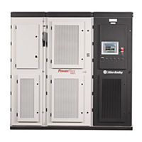
Rockwell Automation PowerFlex 7000 Instructions Manual (214 pages)
Medium Voltage AC Drive Air-Cooled ('B' Frame)—ForGe Control
Brand:
Rockwell Automation
| Category:
DC Drives
| Size: 35.9 MB
Table of Contents
Table of Contents
3
Preface
9
About this Publication
9
Download Firmware, AOP, EDS, and Other Files
9
Summary of Changes
9
Who Should Use this Manual
9
What Is Not in this Manual
9
General Precautions
10
Connect to Service and Support and Product Documentation
11
Abbreviations
11
Additional Resources
12
Powerflex 7000 Drive Overview
13
Topology
13
Rectifier Designs
14
Configurations
14
Cooling Technology
16
Motor Compatibility
17
Simplified Electrical Diagrams
18
2400V
18
3300/4160V
19
6600V
20
Functional Safety
21
Safe Torque off
21
Arcshield Technology
22
Operator Interface
23
Basic Configurations
23
Power Component Definition and Maintenance
25
Control Power off Tests
25
Interlocking
25
Control / Cabling Cabinet Components
27
Voltage-Sensing Assembly
34
Replacing the Voltage-Sensing Circuit Board Assembly
34
Input Transient Protection
35
Transient Suppression Network (TSN)
35
Surge Arresters
39
Filter Capacitor Cabinet
44
Filter Capacitors
44
Filter Capacitor Mounting Plate
45
Replacing Filter Capacitors
46
Testing Filter Capacitors
49
Converter Cabinet Components
51
Powercage Module Overview
56
Resistance Checks
57
SGCT and Snubber Circuit
58
SGCT Testing
64
SGCT Anode-To-Cathode (Sharing) Resistance
64
Snubber Resistance (SGCT Device)
67
Snubber Capacitance (SGCT Device)
68
Replacing the SGCT
69
Replacing Snubber and Sharing Resistor
72
Replacing Sharing Resistors
76
Replacing Snubber Capacitor
76
Silicon Controlled Rectifier Powercage Modules
77
SCR Testing
78
SCR Anode-To-Cathode Resistance
79
SCR Sharing Resistance Test
80
SCR Gate-To-Cathode Resistance
81
Snubber Resistance (SCR Device)
82
Snubber Capacitance (SCR Device)
84
Replacing SCR and SCR Self-Powered Gate Driver Boards
85
(Spgdb)
85
Uniform Clamping Pressure
87
Checking Clamping Pressure
88
Clamping Pressure Adjustment
88
Temperature Sensing
89
Replacing the Thermal Sensor
89
Replacing Heatsinks/Heatpipes
91
Replacing Heatsinks
92
Replacing Heatpipes
93
Powercage Gasket
95
Replacing Powercage Gaskets
96
Removing the Powercage Module
97
Self-Powered SGCT Power Supply - SPS
99
Board Calibration
99
Test Points
99
Testing Equipment
100
Self-Powered Gate Driver Board - SPGDB
101
Board Calibration
101
Test Points
102
Terminal/Connections
103
Testing Procedure for SCR Self-Powered Gate Driver Board
103
Testing Equipment
103
Procedure
103
Fiber Optic Cabling
106
Air Pressure Sensor
107
Replacing the Air Pressure Sensor
107
DC Link Cabinet Components
108
DC Link Reactor
112
Cooling Fans
114
Replacing Ziehl-Abegg Fans
114
Replacing Continental/Daltec Fans
123
Impeller Maintenance
125
Installing Impeller Assembly Onto Motor Shaft
126
Fan Balance
127
Replacing Air Filters
128
Control Component Definition and Maintenance
131
Control Power Components
131
Ride-Through
131
AC/DC Power Supply
133
Terminal / Connections Descriptions (Pioneer Power Supply)
135
Terminal / Connections Descriptions (Cosel Power Supply)
136
Output Calibration
137
Power Supply Replacement
138
Power Supply Diode Replacement
140
UPS Option
141
Replacing the UPS
143
Low Voltage Control Section
144
DC/DC Power Supply
145
Terminal/Connections Descriptions
145
Replacing a DC/DC Power Supply
147
Drive Processor Module
148
Replacing the Drive Processor Module
150
Analog Control Board (ACB)
151
Status Indicators
155
Interface Module (IFM)
155
Analog Inputs and Outputs
156
Current Loop Transmitter
156
Isolated Process Receiver
157
Non-Isolated Process Outputs
158
Auxiliary +24V Power Supply
158
Replacing the Analog Control Board
159
Encoder Feedback Board
159
Encoder Options
159
20B-ENC-3 Encoder Interface
159
Quadrature Encoder Operation
162
Positional Encoder Operations
163
External Input/Output Boards
164
Replacing the External Input/Output Board
165
Optical Interface Boards (OIB)
166
Replacing the Optical Interface Board
167
Replace the Optical Interface Base Board
170
Optical Interface Base Board Test Points
170
Preventative Maintenance Schedule
173
Preventative Maintenance Checklist
173
Operational Maintenance
173
Annual Maintenance
173
Initial Information Gathering
173
Physical Checks (no Medium Voltage and no Control Power)
174
Control Power Checks (no Medium Voltage)
175
Final Power Checks before Restarting
175
Additional Tasks During Preventive Maintenance
176
Final Reporting
176
Time Estimations
177
Tool / Parts / Information Requirements
177
Overview
178
Overview
181
Power Supplies
181
Control Equipment and Boards
182
Sgct/Scr/Sps
183
Cooling Fans
183
Signal Conditioners
183
Spare Parts Maintenance Schedule
184
Spare Parts Connection Matrix
185
Power Supply Connection Guidelines
186
Pioneer/Cosel Power Supply
186
Igdps
186
Intellivac Control Module
187
Absopulse AC/DC Converter
187
Absopulse DC/DC Converter
188
1606 Power Supply
189
Control Equipment and Boards Connection Guidelines
189
Analog Control Board (ACB)
189
Power Components Connection Guidelines
190
Sgct - Igdps
190
SGCT - SPS Board
191
SPS Board
191
Scr - Spgdb
192
Connection Wires Size
193
Torque Requirements for Threaded Fasteners
195
Overview
197
Insulation Resistance Test
197
Insulation Resistance Test Procedure
198
Required Equipment
198
Procedure
198
Air Quality Requirements
203
Hazardous Materials
204
Capacitor Dielectric Fluid
204
Printed Circuit Boards
204
Lithium Batteries
204
Chromate Plating
204
In Case of Fire
205
Disposal
205
Rockwell Automation PowerFlex 7000 Tech Note (17 pages)
Brand:
Rockwell Automation
| Category:
DC Drives
| Size: 0.63 MB
Advertisement
Advertisement
Related Products
Rockwell Automation PowerFlex 700S
Rockwell Automation PowerFlex 700
Rockwell Automation PowerFlex 700L
Rockwell Automation PowerFlex 700H
Rockwell Automation Allen-Bradley PowerFlex 7000A
Rockwell Automation Allen-Bradley PowerFlex 7000L
Rockwell Automation MagneMotion 700-0871-00
Rockwell Automation MagneMotion 700-1573-00
Rockwell Automation MagneMotion 700-1842-00
Rockwell Automation PowerFlex 750-Series
Rockwell Automation Categories
Controller
Control Unit
Power Supply
DC Drives
Industrial Equipment
More Rockwell Automation Manuals
Login
Sign In
OR
Sign in with Facebook
Sign in with Google
Upload manual
Upload from disk
Upload from URL