Sign In
Upload
Manuals
Brands
OMRON Manuals
Computer Hardware
OMNUC G5
OMRON OMNUC G5 Manuals
Manuals and User Guides for OMRON OMNUC G5. We have
1
OMRON OMNUC G5 manual available for free PDF download: User Manual
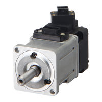
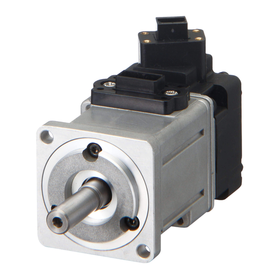
OMRON OMNUC G5 User Manual (550 pages)
AC SERVOMOTORS/SERVO DRIVES
Brand:
OMRON
| Category:
Computer Hardware
| Size: 39.02 MB
Table of Contents
Table of Contents
16
Safety Precautions Document
6
Items to Check after Unpacking
13
Manual Revision History
14
Structure of this Document
15
Table of Contents
16
Chapter 1 Features and System Configuration
20
Outline
20
Features of the OMNUC G5 Series
20
Outline of the OMNUC G5 Series
20
System Configuration
21
Names and Functions
22
Driver Part Names
22
Driver Functions
23
System Block Diagrams
24
Applicable Standards
25
EC Directives
25
Functional Safety
25
UL and Cul Standards
25
Standard Models and External Dimensions
27
Chapter 2 Standard Models and External Dimensions
28
Servo System Configuration
28
How to Read Model
30
Servo Drive
30
Servomotor
31
Standard Model List
32
Servo Drive Model List
32
Servomotor Model List
33
Servo Drive and Servomotor Combination List
37
Peripheral Equipment and Cable Model List
39
External and Mounting Dimensions
49
Servo Drive Dimensions
49
Servomotor Dimensions
61
External Regeneration Resistor Dimensions
80
EMC Filter Dimensions
81
Specifications
83
Chapter 3 Specifications
84
Driver Specifications
84
General Specifications
84
Characteristics
85
Main Circuit and Motor Connections
91
Control I/O Connector Specifications (CN1)
96
Control Input Circuits
106
Control Input Details
110
Control Output Circuits
122
Control Output Details
123
Encoder Connector Specifications (CN2)
128
External Encoder Connector Specifications (CN4)
128
Monitor Connector Specifications (CN5)
132
USB Connector Specifications (CN7)
133
Safety Connector Specifications (CN8)
134
Overload Characteristics (Electronic Thermal Function)
136
Overload Characteristics Graphs
136
Motor Specifications
137
General Specifications
137
Characteristics
138
Encoder Specifications
160
Cable and Connector Specifications
161
Encoder Cable Specifications
161
Motor Power Cable Specifications
163
Connector Specifications
169
Analog Monitor Cable Specifications
172
Control Cable Specifications
174
Servo Relay Units and Cable Specifications
189
Servo Relay Units Specifications
189
Servo Drive-Servo Relay Unit Cable Specifications
202
Position Control Unit-Servo Relay Unit Cable Specifications
206
External Regeneration Resistor Specifications
219
EMC Filter Specifications
221
System Design
223
Chapter 4 System Design
224
Installation Conditions
224
Servo Drive Installation Conditions
224
Servomotor Installation Conditions
226
Gearbox Installation Conditions
229
Wiring
230
Peripheral Equipment Connection Examples
230
Main Circuit and Motor Connections
236
Wiring Conforming to EMC Directives
244
Wiring Method
244
Selecting Connection Component
248
Regenerative Energy Absorption
260
Calculating the Regenerative Energy
260
Driver Regeneration Absorption Capacity
262
Regenerative Energy Absorption with an External Regeneration Resistor
263
Connecting an External Regeneration Resistor
264
Basic Control Mode
267
Chapter 5 BASIC CONTROL Mode
268
Position Control
268
Outline of Operation
268
Parameters Requiring Settings
269
Related Functions
271
Parameter Block Diagram for POSITION CONTROL Mode
272
Speed Control
273
Outline of Operation
273
Parameters Requiring Settings
273
Related Functions
277
Parameter Block Diagram for SPEED CONTROL Mode
278
Torque Control
279
Outline of Operation
279
Parameters Requiring Settings
279
Related Functions
282
Parameter Block Diagram for TORQUE CONTROL Mode
283
Internally Set Speed Control
284
Outline of Operation
284
Parameters Requiring Settings
284
Switching Control
287
Outline of Operation
287
Parameters Requiring Settings
287
Related Functions
289
Full Closing Control
290
Full Closing Control
291
Parameters Requiring Settings
291
Parameter Block Diagram for FULL CLOSING CONTROL Mode
298
Chapter6 Applied Functions
299
Damping Control
301
Adaptive Filter
305
Notch Filter
307
Electronic Gear Function
310
Encoder Dividing Function
313
Brake Interlock
318
Gain Switching Function
323
Torque Limit
331
Sequence I/O Signal
334
Forward and Reverse Drive Prohibition Functions
340
Disturbance Observer Function
343
Gain Switching 3 Function
345
Friction Torque Compensation Function
346
Inertia Ratio Switching Function
348
Hybrid Vibration Suppression Function
349
Feed-Forward Function
350
Instantaneous Speed Observer Function
354
Chapter7 Safety Function
357
Safe Torque off (STO) Function
358
Operation Example
361
Connection Examples
363
Chapter8 Parameters Details
365
Basic Parameters
366
Gain Parameters
374
Vibration Suppression Parameters
385
Analog Control Parameters
390
Interface Monitor Setting Parameters
401
Extended Parameters
411
Special Parameters
424
Chapter9 Operation
431
Operational Procedure
432
Preparing for Operation
433
Using the Front Display
437
Setting the Mode
438
Trial Operation
464
Chapter10 Adjustment Functions
469
Gain Adjustment
470
Realtime Autotuning
472
Manual Tuning
479
Chapter11 Error And Maintenance
487
Error Processing
488
Warning List
491
Alarm List
492
Troubleshooting
496
Periodic Maintenance
507
Chapter12 Appendix
511
Connection Examples
512
Parameter List
522
Index
543
Advertisement
Advertisement
Related Products
OMRON OMNUC G
Omron OMNUC G5 Series
Omron OMNUC G Series
Omron OMNUC U Series
Omron OMNUC W Series
Omron OMNUC H Series
Omron OMNUC M Series
Omron OMNUC R Series
Omron OMNUC FND Series
Omron Omnus FND-X Series
OMRON Categories
Blood Pressure Monitor
Controller
Accessories
Switch
Inverter
More OMRON Manuals
Login
Sign In
OR
Sign in with Facebook
Sign in with Google
Upload manual
Upload from disk
Upload from URL