Sign In
Upload
Manuals
Brands
Nortel Manuals
IP Phone
1100 Series
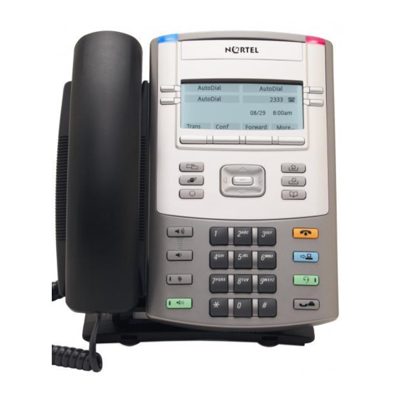
Nortel 1100 Series Manuals
Manuals and User Guides for Nortel 1100 Series. We have
11
Nortel 1100 Series manuals available for free PDF download: Installation And Operation Manual, Configuration, User Manual, Installation Manual, Installing, Connecting Manual, Getting Started
Nortel 1100 Series Installation And Operation Manual (602 pages)
Nortel Communication Server 1000
Brand:
Nortel
| Category:
IP Phone
| Size: 11 MB
Table of Contents
Table of Contents
7
Revision History
3
Description
12
List of Procedures
19
Table of Contents
20
How to Get Help
31
Getting Help from the Nortel Web Site
31
Getting Help over the Phone from a Nortel Solutions Center
31
Getting Help from a Specialist by Using an Express Routing Code
32
Getting Help through a Nortel Distributor or Reseller
32
About this Document
33
Subject
33
Applicable Systems
34
Intended Audience
35
Conventions
35
Related Information
36
Nortel IP Phone 2001
39
Contents
39
Introduction
39
Components and Functions
39
Supported Features
39
Features Not Currently Supported
39
Description
40
Components and Functions
41
Supported Features
44
Features Not Currently Supported
46
Display Characteristics
46
Cleaning the IP Phone Display Screen
48
Key Number Assignments
48
Package Components
49
Installation and Configuration
50
Description
56
Full Duplex Mode
67
Gratuitous Address Resolution Protocol Protection
69
Extensible Authentication Protocol
69
Reinstalling an IP Phone 2001
69
Replacing an IP Phone 2001
71
Removing an IP Phone 2001 from Service
71
Nortel IP Phone 2002
73
Contents
73
Introduction
74
Description
74
Components and Functions
75
Supported Features
79
Features Not Currently Supported
81
Display Characteristics
82
Cleaning the IP Phone Display Screen
84
Key Number Assignments
84
Package Components
84
Installation and Configuration
86
Installing the IP Phone 2002 for the
91
Procedure 11
98
Installing an IP Phone 2002 for the First Time
98
Using DHCP
98
Full Duplex Mode
105
Procedure 12
105
Enabling Full Duplex Mode
105
Procedure 13
106
Checking Ethernet Statistics
106
Gratuitous Address Resolution Protocol Protection
107
Extensible Authentication Protocol
107
Reinstalling an IP Phone 2002
107
Procedure 14
107
Changing the TN of an Existing IP Phone 2002
107
Replacing an IP Phone 2002
108
Procedure 15
108
Removing an IP Phone 2002 from Service
109
Procedure 16
109
Nortel IP Phone 2004
111
Contents
111
Introduction
112
Description
112
Components and Functions
113
Supported Features
117
Features Not Currently Supported
119
Central Answering Postion
119
Display Characteristics
120
Cleaning the IP Phone Display Screen
122
Key Number Assignments
122
Package Components
122
Installation and Configuration
124
Procedure 17
125
Configuring the IP Phone 2004
125
Procedure 18
130
Installing the IP Phone 2004 for the First Time Using Manual Configuration
130
Procedure 19
137
Installing an IP Phone 2004 for the First Time Using DHCP
137
Full Duplex Mode
144
Procedure 20
144
Enabling Full Duplex Mode
144
Gratuitous Address Resolution Protocol Protection
145
Procedure 21
145
Checking Ethernet Statistics
145
Extensible Authentication Protocol
146
Reinstalling an IP Phone 2004
146
Replacing an IP Phone 2004
147
Removing an IP Phone 2004 from Service
148
Nortel IP Phone 2007
149
Contents
149
Description
150
Introduction
150
Components and Functions
151
Supported Features
156
Dialpad Entry
159
Features Not Currently Supported
159
Touch Panel
159
Cleaning the IP Phone Display Screen
161
Display Characteristics
161
Application Area
162
Local Tools Menu Password Protection
165
Key Number Assignments
168
Package Components
168
Installation and Configuration
170
Full Duplex Mode
183
Gratuitous Address Resolution Protocol Protection
185
Extensible Authentication Protocol
185
Reinstalling an IP Phone 2007
185
Replacing an IP Phone 2007
187
Removing an IP Phone 2007 from Service
187
IP Phone Key Expansion Module (Kem)
189
Features
190
Display Characteristics
191
Key Number Assignments
191
Package Components
191
Configuration
192
Installation
196
IP Phone KEM Startup Initialization
198
Operating Parameters
199
Language Support
207
Call Control Window
207
Echo Cancellation
215
Jitter Buffer
216
MVC 2050 Call Handling Screen
238
Software Requirements
257
MVC 2050 Installation Method
259
Roaming and Handover
280
Nortel IP Audio Conference Phone 2033
281
Components and Functions
284
Extension Microphones
284
Supported Features
287
Display Characteristics
289
Key Number Assignments
292
Package Components
293
Full Duplex Mode
319
Configuring the Ip Phone 1120E
339
Installation and Configuration
319
Nortel IP Phone 1140E
361
Supported Features
369
Features Not Currently Supported
372
Display Characteristics
373
Local Tools Menu Password Protection
375
Key Number Assignments
377
Package Components
378
Installation and Configuration
379
Configuring the Ip Phone 1140E
381
Full Duplex Mode
397
Extensible Authentication Protocol
399
Gratuitous Address Resolution Protocol Protection
399
TFTP Firmware Upgrade
399
Reinstalling an IP Phone 1140E
400
Removing an IP Phone 1140E from Service
401
Replacing an IP Phone 1140E
401
Nortel IP Phone 1150E
403
Supported Features
413
Display Characteristics
417
Features Not Currently Supported
417
Headset Support
420
Local Tools Menu Password Protection
420
Key Number Assignments
423
Package Components
425
Installation and Configuration
426
Full Duplex Mode
444
TFTP Firmware Upgrade
446
Bluetooth Wireless Technology
447
Extensible Authentication Protocol
447
Gratuitous Address Resolution Protocol Protection
447
Reinstalling an IP Phone 1150E
447
Removing an IP Phone 1150E from Service
449
Replacing an IP Phone 1150E
449
Expansion Module for IP Phone 1100 Series
451
Features
453
Display Characteristics
454
Package Components
454
Configuration
455
Installation
456
Expansion Module Startup Initialization
460
Operating Parameters
462
IP Phone 1120E
462
IP Phone 1140E and IP Phone 1150E
462
Services Key Operation
463
Display Diagnostics
464
Set Info
465
Firmware
465
Corporate Directory
468
Personal Directory
468
Redial List
469
Callers List
469
Password Administration
469
Regulatory and Safety Information
475
Environmental Specifications
482
Appendix B: 802.1Q VLAN Description
483
Description
484
IP Phone Support
485
IP Softphone 2050 Support
486
Three-Port Switch Support
486
VLAN Ids
487
Automatic VOICE VLAN ID Configuration
487
Enhanced VLAN Tagging
488
Enhanced DATA VLAN
489
Appendix E: IP Phone Diagnostic Utilities
497
Text-Based Diagnostic Utilities
498
Network Diagnostic Utilities
498
Accessing Network Diagnostic Utilities from the IP Phone
501
Network Diagnostic Utilities Data Display Pages
512
Network Address Translation Traversal
525
General Information
526
Using CLI Commands
529
Graphic-Based Diagnostics Utilities
531
Local Diagnostics for the IP Phone 2007
532
Local Diagnostics for the IP Phone 1120E, IP Phone 1140E, and IP Phone 1150E
538
Network Configuration
549
Local Diagnostics
553
Lock Menu
554
Advertisement
Nortel 1100 Series Configuration (178 pages)
VPN Router — Basic Features
Brand:
Nortel
| Category:
Network Router
| Size: 1 MB
Table of Contents
Restricted Rights Legend
2
Table of Contents
5
Preface
15
Before You Begin
15
Text Conventions
15
Acronyms
17
Related Publications
19
Hard-Copy Technical Manuals
20
How to Get Help
20
Finding the Latest Updates on the Nortel Web Site
20
Getting Help from the Nortel Web Site
20
Getting Help over the Phone from a Nortel Solutions Center
21
Getting Help from a Specialist by Using an Express Routing Code
21
Getting Help through a Nortel Distributor or Reseller
21
New in this Release
23
Features
23
Systemlog Lifetime or Disk Size Limit Usage Option
24
FTP Server Passive Mode Parameter
24
Source Ips Access Restriction to Management
24
SSH Server Configurations
24
Overview
25
Network Deployment Alternatives
25
Virtual Private Networking
26
Figure 1 Typical PDN
26
Licensing Features
27
Figure 2 VPN Service Models
27
Command Line Interface
28
Federal Information Processing Standard (FIPS)
28
Getting Started
29
IP Addressing
29
Figure 3 Sample IP Addressing Scheme
30
Table 1 Sample IP Addressing Associations
30
Management Virtual Address
31
Figure 4 MVA on Separate Subnet from Private Physical Interfaces
32
Figure 5 MVA on same Subnet as Private Physical Interface
33
Figure 6 MVA Managing from a Remote PC
33
Configuring MVA with the Serial Menu
34
Configuring Interfaces
36
Multinetting
38
Table 2 Services Supported on a Multinetted Interface
39
Changing the Management IP Address
41
Figure 7 Deployment Scenario
41
Restricting Source Ips Access to Management
44
Configuring ACL through the CLI
44
Accessing ACL through the GUI
45
Configuring the Serial Interface
45
Using Boot Modes
50
Managing through a Web Browser
50
Preparing for Configuration
52
Table 3 Web Interface Configuration Options
53
Table 4 Configuration Checklist
53
Welcome Window
56
Setting up the Nortel VPN Router 1010, 1050, and 1100
59
Default Configuration
59
Figure 8 Default Configuration
60
Branch Office Quick Start Utility
61
Enterprise Environment
62
Service Provider Environment
63
Table 5 Subnet Assignments
63
Deployment Procedure
65
Table 6 BOQS Parameters
66
Branch Office Quick Start Template
67
Connecting for Internet Access
67
Before You Begin
67
Check that You Received the Following Items
67
Cable the VPN Router and Turn the Power on
68
Make Sure that Your Pcs Can Obtain IP Addresses Automatically
69
Test the VPN Router and Start the Quick-Start Tool
69
DHCP Instructions
70
Pppoe Instructions
70
Static IP Instructions
71
Compact Flash Disk
72
Configuring User Tunnels
75
Figure 9 Tunnel Connection Configuration
75
Configuring Group Characteristics
78
Setting up User Tunnels
81
Configuring Inverse Split Tunneling
85
Figure 10 Inverse Split Tunneling
85
Figure 11 Inverse Split Tunneling
86
Inverse Split Tunneling
87
Using the 0.0.0.0/0 Subnet Wildcard
87
Configuring the Subnet Wildcard
87
Figure 12 Edit > Ipsec Page for Wildcard
88
Table 7 Split Tunneling Mode Options
88
Configuring Tunneling Modes Using the CLI
89
Configuring the System
91
Configuring the System Identity
91
Setting up LAN Interfaces
93
Figure 13 LAN-To-Nortel VPN Router Connection
93
Edit LAN Interface Window
95
Multinetting
97
Figure 14 LAN > Interfaces Window
98
Figure 15 LAN Interfaces > Add IP Address Window
99
Configuring Multinetting Using the CLI
100
Adding an IP Address
100
Deleting an IP Address
100
Table 8 Adding/Deleting a Secondary Address
100
Table 9 Configuring OSPF over a Secondary Address
101
Table 10 Configuring RIP over a Secondary Address
102
Asynchronous Data over TCP
105
Figure 16 Asynchronous Data over TCP
105
Configuring Network Time Protocol (NTP)
106
Configuring System Settings
108
Using Proxy ARP
111
Using the SSH Server to Allow Secure Sessions
112
Using the GUI for SSH Server
112
Enabling the SSH Server
112
Figure 17 SSH Server
112
Configuring the SSH Server
113
Figure 18 Allowed Services Window
114
Using the CLI for SSH Server
115
Defining an SSH Server (CLI)
115
Enabling or Restarting the SSH Server
115
Displaying the Current Settings for the SSH Server
116
Disabling the SSH Server
116
Restricted Product - Export License Requirement
117
Configuring Branch Office Tunnels
119
Figure 19 Typical Branch Office Environment
120
Figure 20 Branch-To-Branch with a Firewall and a Router
121
Figure 21 Indirectly Connected Branch Offices
122
PPTP Nested Tunnels
123
DNS for Branch Office Tunnel Endpoints
124
Vpn Dns
124
Round Robin DNS
125
Figure 22 VPN DNS
125
Figure 23 Failover Example
126
Dynamic DNS
127
Figure 24 Load Balancing Example
127
Configuring a Branch Office
128
Figure 25 Setting up a Branch Office Configuration
129
Adding a Group
130
Adding a Tunnel
130
Configuring a Tunnel Connection
131
Sample Branch Office Configuration
133
Figure 26 Sample Branch Office Configuration
134
Sample Branch Office Procedure
135
Configuring Control Tunnels
137
Control Tunnel Types
138
Figure 27 Branch Office Control Tunnel
138
Figure 28 Sample Control Tunnel Environment
139
Restricted Mode
140
Nailed-Up Control Tunnels
140
Creating Control Tunnels
141
Adding a Group
142
Adding a Control Tunnel
143
Configuring a Control Tunnel Connection
144
Creating a User Control Tunnel from the Serial Interface
146
Configuring Ipsec Mobility and Persistent Mode
147
Figure 29 Example Configuration
148
Configuring Ipsec Mobility and Persistent Mode
148
Ipsec Mobility on Nortel VPN Router
149
Roaming Performance Factors
149
Logging and Status for Clients and Servers
149
Ipsec Mobility and NAT
150
Roaming from Behind NAT to Behind NAT
150
Roaming from Behind NAT to no NAT
151
Roaming from no NAT to Behind NAT
151
Ipsec Mobility in NAT Environment
152
Routing Table Changes
152
Table 11 Configuration Considerations
152
Initial Contact Payload (ICP)
153
Maximum Roaming Time
154
Persistent Tunneling
155
Session Persistence Time
155
Configuring Ipsec Mobility and Persistence
156
Configuring Ipsec Mobility
156
Branch Office Quick Start Template
163
Glossary
165
Index
173
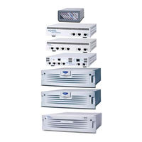
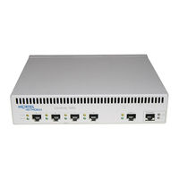
Nortel 1100 Series Installation Manual (64 pages)
VPN Router
Brand:
Nortel
| Category:
Network Router
| Size: 0 MB
Table of Contents
Statement of Conditions
2
Japan/Nippon Requirements Only
3
Table of Contents
7
Features
13
1000BASE-T (1000 GT) Ethernet Card
13
New in this Release
13
Finding the Latest Updates on the Nortel Web Site
15
Getting Help from the Nortel Web Site
15
How to Get Help
15
Getting Help from a Specialist by Using an Express Routing Code
16
Getting Help over the Phone from a Nortel Solutions Center
16
Getting Help through a Nortel Distributor or Reseller
16
Before You Begin
17
Preface
17
Acronyms
18
Text Conventions
18
Related Publications
19
Printed Technical Manuals
20
Chapter 1 Hardware Overview
21
Figure 1 VPN Router 600 1010/1050/1100 Series
21
Table 1 Items Shipped with the VPN Router 600 1010, 1050, and 1100
22
Internal LAN Connections (LAN 0 and LAN 1)
23
Figure 2 VPN Router 600 1010 Front View
23
Figure 3 VPN Router 600 1050 Front View
24
Figure 4 VPN Router 600 1100 Front View
24
Rear View of the Gateway
25
Figure 5 Rear View of the VPN Router 600 1010/1050/1100
25
Connecting the Power Cord
26
Table 2 Power Cord Requirements
26
Understanding the Leds
27
Front Panel Leds
27
Ethernet Port Leds
28
Figure 6 Front Panel of the VPN Router 600 1010
28
Table 3 Front Panel LED Indicators
28
10/100BASE-TX Ethernet Interface Card Leds
29
Figure 7 Leds on the 10/100BASE-TX Ethernet Interface Card
29
Table 4 Ethernet Port LED Indicators
29
Table 5 LED Indicators on the 10/100BASE-TX Ethernet Interface Card
29
1000BASE-T (1000 GT) Ethernet Interface Card Leds
30
Figure 8 Leds on the Full-Height 1000BASE-T (1000 GT) Ethernet Interface Card
30
Figure 9 Leds on the Half-Height 1000BASE-T (1000 GT) Ethernet Card
30
Table 6 LED Indicators on the 1000BASE-T (1000 GT) Ethernet Interface Card
30
56/64K CSU/DSU WAN Interface Card Leds
31
ADSL WAN Interface Card Leds
31
Figure 10 Leds on the 56/64K CSU/DSU WAN Interface Card
31
Figure 11 Leds on the ADSL WAN Interface Card
31
Table 7 LED Indicators on the 56/64K CSU/DSU WAN Interface Card
31
T1/E1 CSU/DSU WAN Interface Card Leds
32
Figure 12 Leds on the T1/E1 CSU/DSU WAN Interface Card
32
Table 8 LED Indicators on the ADSL WAN Interface Card
32
Single V.35/X.21 WAN Interface Card Leds
33
Figure 13 Leds on the Single V.35/X.21 WAN Interface Card
33
Table 9 LED Indicators on the T1/E1 CSU/DSU WAN Interface Card
33
Table 10 LED Indicators on the Single V.35/X.21 WAN Interface Card
33
Chapter 2 Installing Option Cards in the Nortel VPN Router 1100
35
Table 11 Supported Option Cards for the Nortel VPN Router 600 1100
35
Figure 14 VPN Router 600 1100 System Board
37
Appendix A Technical Specifications
41
Technical Specifications
41
Chassis Specifications
41
Table 12 Physical Specifications
41
Table 13 Electrical and Environmental Specifications
41
System Ports
42
10/100BASE-TX Ethernet LAN Ports
42
Serial Port
43
Table 14 10/100BASE-TX Ethernet Port Pinouts
43
Figure 15 Serial Cable (RJ-45-To-DB9)
44
Table 15 RJ-45 to DB9 Pinouts
44
External Modem Adapter
45
Figure 16 Serial Cable Adapter for Connection to Modem (DB9-To-DB25)
45
Table 16 Null Modem Adapter Cable Pinouts
45
Hardware Option Cards
46
10/100BASE-TX Ethernet Interface Card
47
1000BASE-T (1000 GT) Ethernet Interface Card
47
Figure 17 10/100BASE-TX Ethernet Interface Card
47
Figure 18 VPN Router 1100 Full-Height 1000BASE-T (1000 GT)
48
Figure 19 VPN Router 1100 Half-Height 1000BASE-T (1000 GT)
48
56/64K CSU/DSU WAN Interface Card
49
Figure 20 56/64K CSU/DSU WAN Interface Card
49
Table 17 1000BASE-T (1000 GT) Ethernet Pinouts
49
Table 18 56/64K CSU/DSU Cable Pinouts for Crossover Connection
50
ADSL WAN Interface Card
51
Figure 21 ADSL WAN Interface Card
51
Table 19 56/64K CSU/DSU Cable Pinouts for Straight-Through Connection
51
ISDN BRI Interface Card
52
Figure 22 ISDN BRI S/T Interface Card
52
Figure 23 ISDN BRI U Interface Card
52
Table 20 ADSL Cable Pinouts
52
Table 21 ISDN BRI S/T Cable Pinouts
53
Table 22 ISDN BRI U Cable Pinouts
53
T1/E1 CSU/DSU WAN Interface Card
54
Figure 24 T1/E1 CSU/DSU WAN Interface Card
54
Table 23 T1/E1 CSU/DSU Cable Pinouts for Crossover Connection
55
Table 24 T1/E1 CSU/DSU Cable Pinouts for Straight-Through Connection
55
V.90 Modem Interface Card
56
Figure 25 V.90 Modem Interface Card
56
Table 25 V.90 Modem Cable Pinouts
56
Single V.35/X.21 WAN Interface Card
57
Figure 26 Single V.35/X.21 WAN Interface Card
57
Table 26 V.35 Cable Pinouts
57
Table 27 X.21 Cable Pinouts
59
Index
61
Advertisement
Nortel 1100 Series User Manual (67 pages)
VPN Router v7.05; Client Workstation v7.11 Security Target, Version 3.9
Brand:
Nortel
| Category:
Network Router
| Size: 1 MB
Table of Contents
Revision History
2
Table of Contents
3
Table of Figures
4
Table of Tables
4
1 Security Target Introduction
5
Purpose
5
Security Target, TOE and CC Identification and Conformance
5
Able 1 - St, Toe, and CC Identification and Onformance
5
Conventions, Acronyms, and Terminology
6
Conventions
6
Terminology
6
Table 2 - Terminology
6
2 Toe Description
8
Product Type
8
Product Description
8
Vpn Client Deployment Configuration of the Toe
8
Figure 2 - Branch Office Deployment Configuration of the Toe
9
Toe Boundaries and Scope
10
Physical Boundary
10
Figure 3 - Physical Toe Boundary
10
Figure 4 - Physical Toe Boundary in Branch Office Tunnel Mode
10
Logical Boundary
11
Toe Logical Boundary
12
Toe Logical Boundary in Branch Office Tunnel Mode
12
Excluded TOE Functionality
15
3 Toe Security Environment
16
Assumptions
16
Threats to Security
16
Threats Addressed by the TOE
17
Threats Addressed by the TOE Environment
17
4 Security Objectives
18
Security Objectives for the Toe
18
Security Objectives for the Environment
19
IT Security Objectives
19
Non-IT Security Objectives
19
5 It Security Requirements
20
Toe Security Functional Requirements
20
Able 3 - Toe Security Functional Requirements
20
Class FAU: Security Audit
22
Table 4 - Auditable Events
22
Class FCS: Cryptographic Support
24
Class FDP: User Data Protection
27
Class FIA: Identification and Authentication
31
Class FMT: Security Management
33
Class FPT: Protection of the TSF
37
Class FTP: Trusted Path/Channels
38
Security Functional Requirements on the It Environment
39
Able 5 - It Environment Security Functional Requirements
39
Assurance Requirements
41
Table 6 - Assurance Components
41
6 Toe Summary Specification
42
Toe Security Functions
42
Table 7 - Mapping of Toe Security Functions to Security Functional Requirements
42
Security Audit
43
Cryptographic Support
45
Table 8 - Fips-V
45
User Data Protection
46
Identification and Authentication
47
Security Management
47
Protection of the TOE Security Functions
48
Trusted Path/Channels
49
Toe Security Assurance Measures
49
Table 9 - Assurance Measures Mapping to Toe Security Assurance Requirements (Sar S )
49
7 Protection Profile Claims
51
Protection Profile Reference
51
8 Rationale
52
Security Objectives Rationale
52
Table 10 - Relationship of Security Threats to Objectives
52
Security Functional Requirements Rationale
55
Table 11 - Relationship of Security Requirements to Objectives
56
Security Assurance Requirements Rationale
60
Rationale for Strength of Function
60
Dependency Rationale
60
Table 12 - Functional Requirements Dependencies
60
Toe Summary Specification Rationale
62
TOE Summary Specification Rationale for the Security Functional Requirements
62
Table 13 - Mapping of Security Functional Requirements to Toe Security Functions
62
TOE Summary Specification Rationale for the Security Assurance Requirements
63
Strength of Function
65
9 Acronyms
66
Table 14 - Acronyms
66
Nortel 1100 Series Installing (54 pages)
Brand:
Nortel
| Category:
Network Hardware
| Size: 1 MB
Table of Contents
Table of Contents
5
Before You Begin
11
Preface
11
Acronyms
12
Text Conventions
12
Related Publications
13
How to Get Help
14
Chapter 1 Hardware Overview
15
Figure 1 Contivity 1010/1050/1100 Series
15
Table 1 Items Shipped with the Contivity 1010, 1050, and 1100
16
Internal LAN Connections (LAN 0 and LAN 1)
17
Figure 2 Contivity 1010 Front View
17
Figure 3 Contivity 1050 Front View
18
Figure 4 Contivity 1100 Front View
18
Rear View of the Gateway
19
Figure 5 Rear View of the Contivity 1010/1050/1100
19
Connecting the Power Cord
20
Table 2 Power Cord Requirements
20
Understanding the Leds
21
Front Panel Leds
21
Figure 6 Front Panel of the Contivity 1010
21
Ethernet Port Leds
22
Table 3 Front Panel LED Indicators
22
Table 4 Ethernet Port LED Indicators
22
10/100BASE Ethernet Interface Card Leds
23
Figure 7 Leds on the 10/100BASE Ethernet Interface Card
23
Table 5 LED Indicators on the 10/100BASE Ethernet Interface Card
23
56/64K CSU/DSU WAN Interface Card Leds
24
Figure 8 Leds on the 56/64K CSU/DSU WAN Interface Card
24
Table 6 LED Indicators on the 56/64K CSU/DSU WAN Interface Card
24
ADSL WAN Interface Card Leds
25
Figure 9 Leds on the ADSL WAN Interface Card
25
Table 7 LED Indicators on the ADSL WAN Interface Card
25
T1/E1 CSU/DSU WAN Interface Card Leds
26
Figure 10 Leds on the T1/E1 CSU/DSU WAN Interface Card
26
Table 8 LED Indicators on the T1/E1 CSU/DSU WAN Interface Card
26
Single V.35/X.21 WAN Interface Card Leds
27
Figure 11 Leds on the Single V.35/X.21 WAN Interface Card
27
Table 9 LED Indicators on the Single V.35/X.21 WAN Interface Card
27
Installing Option Cards in the Contivity 1100
29
Table 10 Supported Option Cards for the Contivity 1100
29
Figure 12 Contivity 1100 System Board
31
Technical Specifications
33
Chassis Specifications
33
Table 11 Physical Specifications
33
Table 12 Electrical and Environmental Specifications
33
System Ports
34
10/100BASE Ethernet LAN Ports
34
Serial Port
35
Figure 13 Serial Cable (RJ-45-To-DB9)
35
Table 13 10/100BASE Ethernet Port Pinouts
35
External Modem Adapter
36
Table 14 RJ-45-To-DB9 Cable Pinouts
36
Figure 14 Serial Cable Adapter for Connection to Modem (DB9-To-DB25)
37
Table 15 Null Modem Adapter Cable Pinouts
37
Hardware Option Cards
38
10/100BASE Ethernet Interface Card
38
Figure 15 10/100BASE Ethernet Interface Card
38
56/64K CSU/DSU WAN Interface Card
39
Figure 16 56/64K CSU/DSU WAN Interface Card
39
Table 16 56/64K CSU/DSU Cable Pinouts for Crossover Connection
40
Table 17 56/64K CSU/DSU Cable Pinouts for Straight-Through Connection
40
ADSL WAN Interface Card
41
Figure 17 ADSL WAN Interface Card
41
Table 18 ADSL Cable Pinouts
41
ISDN BRI Interface Card
42
Figure 18 ISDN BRI S/T Interface Card
42
Figure 19 ISDN BRI U Interface Card
42
Table 19 ISDN BRI S/T Cable Pinouts
43
Table 20 ISDN BRI U Cable Pinouts
43
T1/E1 CSU/DSU WAN Interface Card
44
Figure 20 T1/E1 CSU/DSU WAN Interface Card
44
Table 21 T1/E1 CSU/DSU Cable Pinouts for Crossover Connection
45
Table 22 T1/E1 CSU/DSU Cable Pinouts for Straight-Through Connection
45
V.90 Modem Interface Card
46
Single V.35/X.21 WAN Interface Card
46
Figure 21 V.90 Modem Interface Card
46
Figure 22 Single V.35/X.21 WAN Interface Card
46
Table 23 V.90 Modem Cable Pinouts
46
Table 24 V.35 Cable Pinouts
47
Table 25 X.21 Cable Pinouts
48
Index
51
Nortel 1100 Series User Manual (30 pages)
Business Communications Manager
Brand:
Nortel
| Category:
IP Phone
| Size: 0 MB
Table of Contents
Table of Contents
3
Regulatory and Safety Information
7
Other
8
Other
10
Denan Regulatory Notice for Japan
11
How to Get Help
13
About this Guide
15
Acronyms
15
Audience
15
Getting Started
15
Related Publications
16
Symbols and Conventions Used in this Guide
16
Basic Features
17
Introduction
17
Hearing Aid Compatibility
18
Telephone Controls
19
Local Tools
20
Telephone Display
20
Local Diagnostics Menu
21
Preferences Menu
21
Lock Menu
22
Network Configuration
22
Navigating the Local Tools Menu
23
Selecting the Handset Language
23
Configuring the Telephone Settings
23
Setting the Display Contrast
23
Backlight Timer Tool
24
Server-Based Features
24
Setting the Language
24
Setting the Ring Type
25
Viewing and Editing the Call Log
25
Time Offset
25
Answering a Call
27
Using the Handset
27
Making a Call
27
Making a Internal Call Using Line Keys
27
Making an External Call Using Line Keys
27
Accessing Voice Mail
28
Answering a Call While on an Active Call
28
Placing a Call on Hold
28
Programming a Memory Button for External Autodial
28
Programming Buttons
28
Erasing a Memory Buttons
29
Programming a Memory Button for a Feature
29
Programming a Memory Button for Internal Autodial
29
Nortel 1100 Series User Manual (28 pages)
Expansion Module for IP Phone
Brand:
Nortel
| Category:
Control Unit
| Size: 0 MB
Table of Contents
Table of Contents
3
Regulatory and Safety Information
7
Other
8
Other
10
Denan Regulatory Notice for Japan
11
How to Get Help
13
Getting Started
15
About this Guide
15
Audience
15
Acronyms
15
Symbols and Conventions Used in this Guide
16
Related Publications
16
Introduction
17
Expansion Module Overview
17
Wall Mounting
17
Display
18
Setup and Assembly
19
Controls and Settings
19
Shift/Outbox Key
19
Services Key
19
Display Diagnostics Menu
20
Installing an Expansion Module
21
Installing the Expansion Module
21
Installing a Second or Third Expansion Module
22
Mounting the Expansion Module and Phone on a Wall
23
Adjusting the Tilt Base
23
Expansion Module Startup Initialization
25
Making a Call Using a Line Key
27
Making a Call Using the Speakerphone Key
27
Putting a Call on Hold
27
Using the Handset
27
Programming External Autodial
28
Programming Internal Autodial
28
Programming a Feature
28
Erasing a Programmed Indicator Keys
28
Programming Indicator Keys
28
Nortel 1100 Series User Manual (28 pages)
Expansion Module for IP Phone 1100 Series
Brand:
Nortel
| Category:
Telephone Accessories
| Size: 1 MB
Table of Contents
Revision History
3
Table of Contents
5
About the Expansion Module for IP Phone 1100 Series
7
Description
7
Features
8
Adjusting the Display
9
Expansion Module for IP Phone 1100 Series Font Support
9
Setup and Assembly
10
Installing the Expansion Module
11
Expansion Module Startup Initialization
14
Using the Wall-Mount Option
14
Adjusting the Tilt Base
15
Controls and Settings
16
Shift Key Functionality
16
Services Key Operation
16
Display Diagnostics
17
Regulatory and Safety Information
19
Other
20
Denan Regulatory Notice for Japan
21
Terms You Should Know
23
Index
25
User Guide
28
Nortel 1100 Series User Manual (28 pages)
Expansion Module
Brand:
Nortel
| Category:
IP Phone
| Size: 1 MB
Table of Contents
Revision History
3
Table of Contents
5
About the Expansion Module for IP Phone 1100 Series
7
Description
7
Features
8
Adjusting the Display
9
Setup and Assembly
10
Installing the Expansion Module
11
Expansion Module Startup Initialization
14
Using the Wall-Mount Option
14
Adjusting the Tilt Base
15
Controls and Settings
16
Shift Key Functionality
16
Services Key Operation
16
Display Diagnostics
17
Regulatory and Safety Information
19
Other
20
Denan Regulatory Notice for Japan
21
Terms You Should Know
23
Index
25
User Guide
28
Expansion Module for IP Phone 1100 Series
28
Nortel 1100 Series Connecting Manual (6 pages)
Connecting for VPN Access
Brand:
Nortel
| Category:
Network Router
| Size: 0 MB
Table of Contents
Before You Begin
1
READ ME FIRST: Connecting for VPN Access
1
Check that You Received These Items
1
Cable the VPN Router and Turn the Power on
2
Make Sure that Your Pcs Can Obtain IP Addresses Automatically
3
DHCP Instructions
3
Test the VPN Router and Start the Branch Office Quick-Start Tool
3
Pppoe Instructions
4
Static IP Instructions
4
The Add IP Address Window Appears.
5
Nortel 1100 Series Getting Started (2 pages)
Expansion Module for IP Phone
Brand:
Nortel
| Category:
Control Unit
| Size: 0 MB
Advertisement
Related Products
Nortel 1165E
Nortel 1150E
Nortel 1120
Nortel 1140
Nortel 1140E
Nortel 11 Series
Nortel 1535
Nortel 1220
Nortel 1200 Series
Nortel 12 Series
Nortel Categories
IP Phone
Telephone
Switch
Software
Server
More Nortel Manuals
Login
Sign In
OR
Sign in with Facebook
Sign in with Google
Upload manual
Upload from disk
Upload from URL