Sign In
Upload
Manuals
Brands
Mitsubishi Electric Manuals
Amplifier
MELSER I/O-J4 MR-J4-11KTM
Mitsubishi Electric MELSER I/O-J4 MR-J4-11KTM Manuals
Manuals and User Guides for Mitsubishi Electric MELSER I/O-J4 MR-J4-11KTM. We have
1
Mitsubishi Electric MELSER I/O-J4 MR-J4-11KTM manual available for free PDF download: Instruction Manual
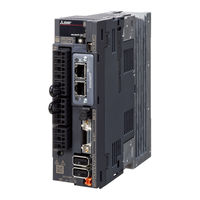
Mitsubishi Electric MELSER I/O-J4 MR-J4-11KTM Instruction Manual (594 pages)
Servo amplifier Melservo-J4
Brand:
Mitsubishi Electric
| Category:
Amplifier
| Size: 9 MB
Table of Contents
Safety Instructions
2
Table of Contents
10
Summary
18
Function Block Diagram
20
Servo Amplifier Standard Specifications
30
Connector
34
Combinations of Servo Amplifiers and Servo Motors
36
Function List
38
Scale Measurement Encoder
40
Model Designation
41
Structure
42
Removal and Reinstallation of the Front Cover
55
Installation and Removal of Network Module
57
Configuration Including Peripheral Equipment
60
Installation Direction and Clearances
75
Keeping out of Foreign Materials
77
Parts Having Service Lives
78
Restrictions When Using the Servo Amplifiers at Altitude Exceeding 1000 M and up to 2000 M above Sea Level
79
Input Power Supply Circuit
82
V Class
83
V Class
89
V Class
93
I/O Signal Connection Example
94
For Source I/O Interface
95
Explanation of Power Supply System
96
Power-On Sequence
97
Wiring CNP1, CNP2, and CNP3
98
Connectors and Pin Assignment
102
Signal (Device) Explanations
103
Output Device
105
Output Signal
106
Forced Stop Deceleration Function
107
Base Circuit Shut-Off Delay Time Function
108
Vertical Axis Freefall Prevention Function
109
Alarm Occurrence Timing Chart
110
When You Do Not Use the Forced Stop Deceleration Function
111
Interfaces
112
Detailed Explanation of Interfaces
113
Source I/O Interfaces
115
Servo Motor with an Electromagnetic Brake
116
Timing Chart
117
Grounding
121
Switching Power on for the First Time
123
Wiring Check
124
Surrounding Environment
127
Switch Setting and Display of the Servo Amplifier
129
Scrolling Display
130
Status Display of an Axis
132
Test Operation
134
Test Operation Mode in MR Configurator2
135
Motor-Less Operation in Controller
138
Parameter List
140
Basic Setting Parameters ([Pr. PA_ _ ])
141
Gain/Filter Setting Parameters ([Pr. PB_ _ ])
142
Extension Setting Parameters ([Pr. PC_ _ ])
143
I/O Setting Parameters ([Pr. PD_ _ ])
146
Extension Setting 2 Parameters ([Pr. PE_ _ ])
147
Extension Setting 3 Parameters ([Pr. PF_ _ ])
148
Linear Servo Motor/DD Motor Setting Parameters ([Pr. PL_ _ ])
150
Positioning Control Parameters ([Pr. PT_ _ ])
151
Network Setting Parameters ([Pr. PN_ _ ])
153
Detailed List of Parameters
154
Gain/Filter Setting Parameters ([Pr. PB_ _ ])
167
Extension Setting Parameters ([Pr. PC_ _ ])
179
I/O Setting Parameters ([Pr. PD_ _ ])
194
Extension Setting 2 Parameters ([Pr. PE_ _ ])
197
Extension Setting 3 Parameters ([Pr. PF_ _ ])
201
Linear Servo Motor/DD Motor Setting Parameters ([Pr. PL_ _ ])
203
Positioning Control Parameters ([Pr. PT_ _ ])
206
Network Setting Parameters ([Pr. PN_ _ ])
221
Software Limit
222
How to Set the Electronic Gear
223
Different Adjustment Methods
226
Adjustment Using MR Configurator2
227
One-Touch Tuning
228
One-Touch Tuning Flowchart
229
Display Transition and Operation Procedure of One-Touch Tuning
230
Caution for One-Touch Tuning
233
Auto Tuning
234
Auto Tuning Mode Basis
235
Adjustment Procedure by Auto Tuning
236
Response Level Setting in Auto Tuning Mode
237
Manual Mode
238
Gain Adjustment Mode
241
Filter Setting
244
Machine Resonance Suppression Filter
245
Adaptive Filter II
248
Shaft Resonance Suppression Filter
250
Low-Pass Filter
251
Command Notch Filter
256
Gain Switching Function
258
Function Block Diagram
259
Parameter
260
Gain Switching Procedure
263
Tough Drive Function
267
Instantaneous Power Failure Tough Drive Function
269
Compliance with SEMI-F47 Standard
273
Model Adaptive Control Disabled
276
Lost Motion Compensation Function
277
Super Trace Control
280
Explanations of the Lists
282
Alarm List
283
Warning List
288
Remedies
290
Troubleshooting at Power on
294
Outline Drawings
312
Overload Protection Characteristics
314
Power Supply Capacity and Generated Loss
318
Dynamic Brake Characteristics
321
Permissible Load to Motor Inertia When the Dynamic Brake Is Used
324
Cable Bending Life
325
Inrush Currents at Power-On of Main Circuit and Control Circuit
326
Cable/Connector Sets
328
Combinations of Cable/Connector Sets
329
MR-D05UDL3M-B STO Cable
331
Battery Cable/Junction Battery Cable
332
Regenerative Options
333
Selection of Regenerative Option
335
Parameter Setting
338
Dimensions
343
FR-BU2-(H) Brake Unit
347
Brake Unit Parameter Setting
348
Connection Example
349
Dimensions
357
FR-RC-(H) Power Regeneration Converter
360
FR-CV-(H) Power Regeneration Common Converter
364
Model Designation
365
Junction Terminal Block PS7DW-20V14B-F (Recommended)
373
MR Configurator2
374
System Configuration
375
Precautions for Using USB Communication Function
376
Battery
377
MR-BAT6V1BJ Battery for Junction Battery Cable
382
MR-BT6VCASE Battery Case
386
MR-BAT6V1 Battery
392
Selection Example of Wires
393
Molded-Case Circuit Breakers, Fuses, Magnetic Contactors
396
Power Factor Improving DC Reactors
399
Power Factor Improving AC Reactors
401
Relay (Recommended)
404
Noise Reduction Techniques
405
Earth-Leakage Current Breaker
413
EMC Filter (Recommended)
416
External Dynamic Brake
423
Panel through Attachment (MR-J4ACN15K/MR-J3ACN)
429
Summary
434
Structure
435
Battery
436
Using MR-BAT6V1BJ Battery for Junction Battery Cable
437
Using MR-BT6VCASE Battery Case
438
Introduction
440
Residual Risks of the STO Function
441
Specifications
442
Maintenance
443
Signal (Device) Explanations
444
Connection Example
445
External I/O Signal Connection Example Using an MR-J3-D05 Safety Logic Unit
446
External I/O Signal Connection Example Using an External Safety Relay Unit
448
Detailed Description of Interfaces
449
Source I/O Interface
451
Functions and Configuration
452
Servo System with Auxiliary Equipment
453
Signals and Wiring
456
Operation and Functions
458
Magnetic Pole Detection
461
Home Position Return
469
Test Operation Mode in MR Configurator2
473
Operation from Controller
474
Function
475
Absolute Position Detection System
477
Characteristics
478
Power Supply Capacity and Generated Loss
479
Dynamic Brake Characteristics
480
Permissible Load to Motor Mass Ratio When the Dynamic Brake Is Used
481
Functions and Configuration
482
Servo System with Auxiliary Equipment
483
Signals and Wiring
484
Operation and Functions
485
Startup Procedure
486
Magnetic Pole Detection
487
Operation from Controller
495
Characteristics
497
Power Supply Capacity and Generated Loss
499
Dynamic Brake Characteristics
500
Functions and Configuration
502
Selecting Procedure of Control Mode
503
System Configuration
504
Load-Side Encoder
505
Operation and Functions
506
Home Position Return
513
Operation from Controller
515
Fully Closed Loop Control Error Detection Functions
516
Auto Tuning Function
517
Absolute Position Detection System under Fully Closed Loop System
518
About MR Configurator2
519
How to Use the Scale Measurement Function
526
Appendix
538
App. 1 When Using the Servo Amplifier with the DC Power Supply Input
538
App. 2 Handling of AC Servo Amplifier Batteries for the United Nations Recommendations on the Transport of Dangerous Goods
542
App. 3 Symbol for the New EU Battery Directive
545
App. 4 Compliance with Global Standards
546
App. 5 MR-J3-D05 Safety Logic Unit
559
App. 6 EC Declaration of Conformity
577
App. 7 How to Replace Servo Amplifier Without Magnetic Pole Detection
579
App. 8 Analog Monitor
580
App. 9 Special Specification
584
App. 10 Driving On/Off of Main Circuit Power Supply with DC Power Supply
588
Advertisement
Advertisement
Related Products
Mitsubishi Electric MR-J4-10TM1
Mitsubishi Electric MELSER I/O-J4 MR-J4-15KTM
Mitsubishi Electric MELSER I/O-J4 MR-J4-11KTM4
Mitsubishi Electric MELSER I/O-J4 MR-J4-15KTM4
Mitsubishi Electric MR-J4W3
Mitsubishi Electric MR-J4W2-0303B6
Mitsubishi Electric MR-J4 TM Series
Mitsubishi Electric MELSERVO MR-J4W-B Series
Mitsubishi Electric MR-J4-_GF
Mitsubishi Electric MELSER I/O-J4 MR-J4-500TM
Mitsubishi Electric Categories
Air Conditioner
Controller
Projector
Inverter
Heat Pump
More Mitsubishi Electric Manuals
Login
Sign In
OR
Sign in with Facebook
Sign in with Google
Upload manual
Upload from disk
Upload from URL