Sign In
Upload
Manuals
Brands
Manitowoc Manuals
Construction Equipment
Grove RT530E-2
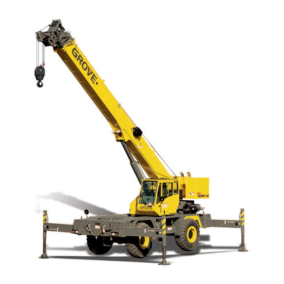
Manitowoc Grove RT530E-2 Manuals
Manuals and User Guides for Manitowoc Grove RT530E-2. We have
3
Manitowoc Grove RT530E-2 manuals available for free PDF download: Service And Maintenance Manual, Operator's Manual, Product Manual
Manitowoc Grove RT530E-2 Service And Maintenance Manual (314 pages)
Brand:
Manitowoc
| Category:
Construction Equipment
| Size: 9.32 MB
Table of Contents
Table of Contents
5
Section 1
13
List of Specifications
14
General
14
Dimensions
14
Capacities
14
Torque Converter/Transmission
14
Engine
14
Axles
14
Brakes
14
Wheels and Tires
14
Swing Gearbox
14
Hydraulic Pumps
15
General Maintenance
20
Cleanliness
20
Removal and Installation
20
Disassembly and Assembly
20
Pressing Parts
20
Locks
20
Wires and Cables
21
Shims
21
Bearings
21
Gaskets
21
Batteries
21
Hydraulic Systems
22
Electrical System
23
Fatigue of Welded Structures
23
Loctite
24
Fasteners and Torque Values
24
Weld Studs
28
Wire Rope
29
General
29
Environmental Conditions
29
Dynamic Shock Loads
29
Lubrication
29
Precautions and Recommendations During Inspection or Replacement
29
Wire Rope Inspection (Running Ropes and pendant Cables)
30
Wire Rope Inspection (Boom Extension and Retraction Cables)
31
Wire Rope Inspection/Replacement (All Wire Rope)
31
Seizing Wire Rope
32
Installing 35X7 Class Wire Rope
33
Procedures for Cutting and Preparing 35X7 Class Wire Rope
33
Section 2
35
Description
36
Maintenance
39
Hydraulic Oil Recommendations
39
Draining and Flushing
39
Removing Air from the Hydraulic System
40
Parts Replacement
40
Directional Control Valves
40
Supply Pressure and Return Circuit
42
Description
42
Maintenance
43
Oil Cooler
47
Description
47
Hydraulic Pumps
48
Description
48
Maintenance
48
Pressure Setting Procedures
51
Procedure a - for Checking/Setting the Main Control Valve for Hoists(S), Boom Lift and Piston Pump
53
Procedure B - for Setting the Outrigger/Rear Steer/Oil Cooler Motor Pressures
53
Procedure C - for Checking/Setting the Swing Directional Control Valve Work Port Relief Valves
54
Procedure C - for Checking/Setting the Swing Direc- Tional Control Valve Work Port Relief Valves
54
Procedure D - for Checking/Setting the Service Brake Dual Accumulator Charge Valve Charging Limits
54
Procedure E - for Checking/Pre-Charging the Service Brake Accumulators
54
Procedure F - for Checking/Setting the Front Steer Pressure
55
Procedure G - for Checking/Setting the Pilot Supply Pressure
55
Procedure H - for Checking/Setting the Swing Brake Release Pressure
55
Procedure J - for Setting Threshold on Electronic Controllers
55
Procedure K - Setting Threshold and Max on Swing Brake Pedal
56
Valves
61
General
61
Directional Control Valves
64
Description
64
Maintenance
64
Accessory with Swing Directional Control Manifold
67
Description
67
Maintenance
67
Steering Control Valve
69
Description
69
Maintenance
69
Tandem Brake Valve with Treadle Pedal
70
Description
70
Maintenance
70
Dual Accumulator Charge Valve
71
Description
71
Maintenance
71
Hydraulic Accumulator Service Brake
73
Description
73
Maintenance
73
Holding Valves
74
Description
74
Maintenance
74
Cross Axle Differential Lock Valve
75
Description
75
Maintenance
75
Outrigger Control Manifold
77
Description
77
Maintenance
77
Pilot Operated Check Valve
78
Description
78
Maintenance
78
Integrated Outrigger/Rear Steer Manifold
79
Description
79
Maintenance
79
Check Valves
82
Description
82
Maintenance
82
Range Shift/Parking Brake Valve
83
Description
83
Maintenance
83
Axle Oscillation Lockout Valve (Standard Units)
84
Description
84
Maintenance
84
Axle Oscillation Lockout Valve (Optional CE Units)
86
Description
86
Maintenance
86
Cylinders
88
General
88
Maintenance
88
Surface Protection for Cylinder Rods
88
Lift Cylinder
91
Description
91
Maintenance
91
Dual Rod Telescope Cylinder
94
Description
94
Maintenance
94
Axle Oscillation Lockout Cylinder
98
Description
98
Maintenance
98
Steer Cylinder
102
Description
102
Maintenance
102
Outrigger Extension Cylinder
105
Description
105
Maintenance
105
Outrigger Jack Cylinder
107
Description
107
Maintenance
107
Description
111
General
111
Batteries
111
Fuse Panel
112
Relays
113
Maintenance
114
General
114
General Troubleshooting
114
Troubleshooting Swivel-Caused Electrical Problems
114
Connector Troubleshooting
114
Troubleshooting Engine Starting Problems
115
Troubleshooting Engine Charging Problems
115
Troubleshooting Accessories
116
Electric System
116
Alternator Replacement
117
Starter Replacement
117
Battery Replacement
118
Relay Panel Component Replacement
118
Rocker Switch Replacement
118
Ignition Switch Replacement
119
Turn Signal Lever and Transmission Shift Lever Replacement
120
Windshield Wiper Assembly Replacement
122
Windshield Washer Assembly Replacement
123
Skylight Wiper Assembly Replacement
123
Appendix A: Crane Control System (CCS) Fault Codes
126
Section 4
149
Description
149
Theory of Operation
149
Boom Extension
149
Boom Retraction
150
Maintenance
154
Removal
154
Boom Disassembly
154
Remove the Base Section
154
Disconnect Inner MID Section
156
Remove the Inner MID Section
157
Remove Outer MID Section
158
Remove Telescope Cylinder
160
Boom Nose Sheaves
161
Boom Assembly
161
Install Telescope Cylinder
161
Install Outer MID Section
162
Install Inner MID Section
164
Connect Inner MID Section
165
Install Base Section
166
Boom Installation
167
Functional Check
167
Inspection
167
Boom Alignment and Servicing
167
Boom Extension and Retraction Cable
168
Maintenance
168
Inspection
168
Extension Cable Adjustment
168
Retract Cable Adjustment
169
Telescope Circuit
169
Description
169
Theory of Operation
169
Maintenance
170
Lift Circuit
173
Description
173
Theory of Operation
173
Maintenance
173
Swingaway Boom Extension
177
Description
177
Maintenance
177
Hook Block
182
Description
183
Warm-Up Procedure
183
Removal
184
Installation
185
Functional Check
185
Servicing
185
Fluid Level
185
Usage and Inspection
186
Preventative Maintenance
186
Oil Sampling
188
Brake Test Procedure
188
Hoist to Boom Alignment
189
Preparation
189
Tools Required
189
Procedure
190
Piston Motor and Control Valve
191
Description
191
Maintenance
191
Hoist Drum Rotation Indicator System
194
Description
194
Maintenance
194
Counterweight Removal
196
Description
196
Theory of Operation
199
Description
200
Maintenance
201
Troubleshooting
201
Swing Motor
204
Description
204
Maintenance
204
Swing Gearbox and Brake
205
Description
205
Maintenance
205
Swing Bearing
207
Description
207
Maintenance
207
Swivels
212
Description
212
Hydraulic Swivel
214
Description
214
Electrical Swivel
216
Section 7
219
Engine
219
Description
219
Maintenance
220
Description
223
Fuel System
225
Description
225
Maintenance
225
Description
226
Air Intake and Exhaust System
227
Description
227
Air Intake
227
Charge-Air Cooler System
231
Muffler and Diesel Oxidation Catalyst - Tier 4 Interim
232
Slip Joint Exhaust Connectors
232
Water Cooling System
234
Description
234
Maintenance
234
Test Equipment
237
Antifreeze/Coolant
237
Radiator Removal and Installation
237
Drive Train
239
Description
239
Maintenance
239
Transmission/Torque Converter
239
Theory of Operation
239
Maintenance
240
Servicing the Crane after Transmission/Torque Converter Overhaul
243
Axles
245
Description
245
Maintenance
246
Wheels and Tires
251
Description
251
Maintenance
251
Steering Systems
252
Description
252
Theory of Operation
252
Rear Steering System
252
Hydraulic Pumps
255
Front Steering Control Valve
255
Integrated Outrigger/Rear Steer Manifold
255
Steer Cylinders
256
Rear Axle Oscillation Lockout System
257
Description
257
Axle Oscillation Lockout Cylinders
257
Brake System
258
Description
258
Theory of Operation
258
Maintenance
259
Service Brakes
260
Description
260
Maintenance
260
Corrosion Protection
264
Parking Brake Actuator
266
Description
266
Maintenance
266
Parking Brake
267
Description
267
Maintenance
267
Park Brake Valve
268
Description
268
Outriggers
268
Outrigger Circuit
268
Outrigger Beam
272
Extension Cylinder
276
Jack Cylinder
277
Outrigger Control Valves
279
Section 9
281
General
281
Lubrication Intervals
281
Arctic Conditions below -18°C (0°F)
281
Arctic Conditions down to -40° C (-40°F)
281
Surface Protection for Cylinder Rods
282
Wire Rope Lubrication
282
Lubrication Points
283
Cranelube
283
Safety
283
Steering and Suspension
284
Axles
286
Drive Train
288
Drive Train (Continued)
290
Outriggers
292
Turntable
294
Boom
296
Boom (Continued)
296
Boom (Continued)
298
Hoist
300
Hydraulic
302
Carwell® Rust Inhibitor
304
Protecting Cranes from Rusting
304
Cleaning Procedures
304
Inspection and Repair
305
Application
305
Areas of Application
305
Advertisement
Manitowoc Grove RT530E-2 Operator's Manual (168 pages)
Brand:
Manitowoc
| Category:
Construction Equipment
| Size: 7.38 MB
Table of Contents
Table of Contents
13
Section 1
19
General
19
Noise/Vibration Test Results
19
Noise Level Test Results
19
Vibration Level Test Results
19
Customer Support
19
List of Specifications
20
General
20
Dimensions
20
Capacities
20
Torque Converter/Transmission
20
Engine
20
Axles
20
Brakes
20
Wheels and Tires
20
Swing Gearbox
20
Hydraulic Pumps
21
Serial Number Location
22
Section 2
25
Safety Messages
25
General
26
Safety Alert Symbol
26
Signal Words
26
Warning Signs
26
Accidents
26
Operator Information
26
Operator Qualifications
27
Operational Aids
28
Rated Capacity Limiter (RCL) Systems (if Equipped)
28
Anti-Two-Blocking Device
28
Working Area Limiter (if Equipped)
29
Crane Stability/Structural Strength
30
Load Charts
30
Work Site
30
Wind Forces
31
Wind Speeds
31
Lifting Operations
44
Counterweight
45
Outrigger Lift off
45
Multiple Crane Lifts
45
Tilt-Up Panel Lifting
45
Pile Driving and Extracting
46
Crane Equipment
46
Crane Inspection
46
Electrocution Hazard
47
Set-Up and Operation
48
Electrocution Hazard Devices
48
Electrical Contact
49
Special Operating Conditions and Equipment
49
Personnel Handling
49
Environmental Protection
50
Maintenance
51
Service and Repairs
51
Lubrication
52
Tires
52
Hoist Rope
52
Synthetic Hoist Rope
52
Wire Rope
53
Sheaves
54
Batteries
54
Engine
55
Transporting the Crane
55
Travel Operation
55
Work Practices
56
Personal Considerations
56
Crane Access
56
Job Preparation
57
Working
57
Lifting
58
Hand Signals
59
Jib
61
Parking and Securing
61
Shut-Down
61
Cold Weather Operation
61
Temperature Effects on Hook Blocks
62
Temperature Effects on Hydraulic Cylinders
62
Model Specific Information
64
Overload Inspection
64
Boom Inspection
65
Superstructure Inspection
67
Carrier Inspection
69
Controls and Indicators
72
Steering Column
72
Turn Signal Lever and Windshield Wiper/Washer/Headlight /Horn Controls
73
Steering Column Tilt Lever
73
Park Brake Control Switch
73
Headlights Switch
73
Drive Axle Selector Switch
73
Hazard Lights Switch
73
Increment/Decrement Switch
73
Ignition Switch
73
Transmission Shift Lever
74
Cab Overhead Controls
74
Skylight Window Latch
74
Skylight Wiper and Wiper Motor
74
Skylight Sunscreen
74
Dome Light
74
Cab Circulating Fan
74
Right Side Window Latch
74
Overhead Control Panel
75
Skylight Wiper Switch
75
Heater/Air Conditioner Fan Speed Switch
75
Heater Control Switch
75
Air Conditioner Switch
75
Telescope Control Pedal (Optional)
109
Service Brake Pedal
109
Foot Throttle Pedal
109
Miscellaneous Controls and Indicators
109
Fuse Panel
109
Buzzer
109
RCL Emergency Override Switch (Non-CE Certified Cranes)
110
RCL Emergency Override Switch and Indicator (CE Certified Cranes)
110
RCL Internal Light Bar (Optional)
111
Strobe Light or Beacon (Optional) (Not Shown)
111
Backup Alarm (Not Shown)
111
Emergency Exit
111
Appendix A: Crane Control System (CCS) Symbols and Icons
112
General
117
Installing Cable on the Hoist
117
Cable Reeving
118
Dead-End Rigging/Wedge Sockets
121
Installing Wedge and Socket
121
Dead-End Rigging
122
Erecting and Stowing the Boom Extension
123
General Warnings
123
Erecting
123
Stowing
129
Setting the Offset
129
Changing Boom Extension from Telescoping Type to Fixed Type
130
Setting the Telescoping Extension Length
130
Anti Two Block (A2B) Switch
130
Lock
130
Unlock
131
Before Operation
131
Counterweights
133
Section 5
137
General
137
Environmental Protection
137
Lubrication Intervals
137
Arctic Conditions below -18°C (0°F)
138
Arctic Conditions down to -40°C (-40°F)
139
Surface Protection for Cylinder Rods
141
Wire Rope Lubrication
141
Lubrication Points
141
Cranelube
141
Cummins Oil Registration List
141
Safety
141
Steering and Suspension
142
Axles
144
Drive Train
146
Drive Train (Continued)
148
Outriggers
150
Turntable
152
Boom
154
Boom (Continued)
156
Hoist
158
Hydraulic
160
General
163
Instructions
163
Daily or 10 Hour Check List
163
Weekly or 50 Hour Check List
164
Manitowoc Grove RT530E-2 Product Manual (24 pages)
Brand:
Manitowoc
| Category:
Construction Equipment
| Size: 3.48 MB
Table of Contents
Table of Contents
3
Technische Daten
5
Caractéristiques Techniques
6
Características
7
Caratteristiche Technique
8
Características Técnicas
9
Data • Daten • Caractéristiques • Datos • Dati • Características
10
Dimensions • Abmessungen • Encombrement • Dimensiones • Dimensioni • Dimensões
11
Notes • Hinweise • Notes • Notas • Note • Notas
12
Working Range • Arbeitsbereiche • Diagramme de Levage • Gama de Trabajo • Area DI Lavoro • Intervalo de Funcionamento
13
Telescopic Boom • Teleskopausleger • Flèche Principale • Pluma Telescópica • Braccio Telescopico • Lança Telescópica
14
Swingaway • Klappspitze • Extension Treillis • Plumín • Jib • Swingaway
18
Notes • Hinweise • Notes • Notas • Note • Notas
20
Symbols • Symbolerklärung • Glossaire des Symboles • Glosario de Simbolos • Glossario Dei Simboli • Símbolos
23
Advertisement
Advertisement
Related Products
Manitowoc Grove RT540E
Manitowoc Grove RT9150E
Manitowoc Grove RT890E
Manitowoc Grove RT9130E
Manitowoc GROVE RT650E
Manitowoc Grove RT9130E-2
Manitowoc Grove RT880E
Manitowoc Grove RT765E-2
Manitowoc Grove RT770E
Manitowoc Grove GMK4070E
Manitowoc Categories
Construction Equipment
Ice Maker
Accessories
Commercial Food Equipment
Dispenser
More Manitowoc Manuals
Login
Sign In
OR
Sign in with Facebook
Sign in with Google
Upload manual
Upload from disk
Upload from URL